JP3575763B2 - Hybrid vehicle control device - Google Patents
Hybrid vehicle control device Download PDFInfo
- Publication number
- JP3575763B2 JP3575763B2 JP2002292705A JP2002292705A JP3575763B2 JP 3575763 B2 JP3575763 B2 JP 3575763B2 JP 2002292705 A JP2002292705 A JP 2002292705A JP 2002292705 A JP2002292705 A JP 2002292705A JP 3575763 B2 JP3575763 B2 JP 3575763B2
- Authority
- JP
- Japan
- Prior art keywords
- output
- motor
- driving force
- vehicle
- change
- Prior art date
- Legal status (The legal status is an assumption and is not a legal conclusion. Google has not performed a legal analysis and makes no representation as to the accuracy of the status listed.)
- Expired - Lifetime
Links
- 230000005540 biological transmission Effects 0.000 claims description 17
- 238000000034 method Methods 0.000 description 23
- 238000010586 diagram Methods 0.000 description 14
- 230000008929 regeneration Effects 0.000 description 13
- 238000011069 regeneration method Methods 0.000 description 13
- 239000000446 fuel Substances 0.000 description 11
- 238000001514 detection method Methods 0.000 description 8
- 230000035939 shock Effects 0.000 description 8
- 239000003990 capacitor Substances 0.000 description 7
- 238000002347 injection Methods 0.000 description 5
- 239000007924 injection Substances 0.000 description 5
- 230000007423 decrease Effects 0.000 description 4
- 230000003247 decreasing effect Effects 0.000 description 4
- RLAHNGKRJJEIJL-RFZPGFLSSA-N [(2r,4r)-4-(2,6-diaminopurin-9-yl)-1,3-dioxolan-2-yl]methanol Chemical compound C12=NC(N)=NC(N)=C2N=CN1[C@H]1CO[C@@H](CO)O1 RLAHNGKRJJEIJL-RFZPGFLSSA-N 0.000 description 3
- 239000003054 catalyst Substances 0.000 description 3
- 239000007789 gas Substances 0.000 description 3
- 230000003111 delayed effect Effects 0.000 description 2
- 238000011144 upstream manufacturing Methods 0.000 description 2
- XLYOFNOQVPJJNP-UHFFFAOYSA-N water Substances O XLYOFNOQVPJJNP-UHFFFAOYSA-N 0.000 description 2
- 230000001133 acceleration Effects 0.000 description 1
- QVGXLLKOCUKJST-UHFFFAOYSA-N atomic oxygen Chemical compound [O] QVGXLLKOCUKJST-UHFFFAOYSA-N 0.000 description 1
- 238000002485 combustion reaction Methods 0.000 description 1
- 239000000498 cooling water Substances 0.000 description 1
- 230000000994 depressogenic effect Effects 0.000 description 1
- 238000007599 discharging Methods 0.000 description 1
- 230000000694 effects Effects 0.000 description 1
- 238000005516 engineering process Methods 0.000 description 1
- 239000002828 fuel tank Substances 0.000 description 1
- 239000000203 mixture Substances 0.000 description 1
- 239000001301 oxygen Substances 0.000 description 1
- 229910052760 oxygen Inorganic materials 0.000 description 1
- 230000002093 peripheral effect Effects 0.000 description 1
- 230000001172 regenerating effect Effects 0.000 description 1
Images


Classifications
-
- Y—GENERAL TAGGING OF NEW TECHNOLOGICAL DEVELOPMENTS; GENERAL TAGGING OF CROSS-SECTIONAL TECHNOLOGIES SPANNING OVER SEVERAL SECTIONS OF THE IPC; TECHNICAL SUBJECTS COVERED BY FORMER USPC CROSS-REFERENCE ART COLLECTIONS [XRACs] AND DIGESTS
- Y02—TECHNOLOGIES OR APPLICATIONS FOR MITIGATION OR ADAPTATION AGAINST CLIMATE CHANGE
- Y02T—CLIMATE CHANGE MITIGATION TECHNOLOGIES RELATED TO TRANSPORTATION
- Y02T10/00—Road transport of goods or passengers
- Y02T10/60—Other road transportation technologies with climate change mitigation effect
- Y02T10/62—Hybrid vehicles
-
- Y—GENERAL TAGGING OF NEW TECHNOLOGICAL DEVELOPMENTS; GENERAL TAGGING OF CROSS-SECTIONAL TECHNOLOGIES SPANNING OVER SEVERAL SECTIONS OF THE IPC; TECHNICAL SUBJECTS COVERED BY FORMER USPC CROSS-REFERENCE ART COLLECTIONS [XRACs] AND DIGESTS
- Y02—TECHNOLOGIES OR APPLICATIONS FOR MITIGATION OR ADAPTATION AGAINST CLIMATE CHANGE
- Y02T—CLIMATE CHANGE MITIGATION TECHNOLOGIES RELATED TO TRANSPORTATION
- Y02T10/00—Road transport of goods or passengers
- Y02T10/60—Other road transportation technologies with climate change mitigation effect
- Y02T10/7072—Electromobility specific charging systems or methods for batteries, ultracapacitors, supercapacitors or double-layer capacitors
Description
【0001】
【発明の属する技術分野】
本発明は、原動機としてエンジンおよびモータを備えたハイブリッド車両の制御装置に関する。
【0002】
【従来の技術】
原動機としてエンジンおよびモータを備えたハイブリッド車両は従来より知られており、そのようなハイブリッド車両の原動機の制御装置として、たとえば特許文献1に記載されたものが、エンジンとモータの出力配分を考慮した技術として知られている。
【0003】
【特許文献1】
特開平8−82232号公報
この装置では、アクセルペダルが踏み込まれ、車両運転者が要求する出力トルクが急激に増加したときは、エンジンの出力トルクを徐々に増加させる(具体的には、エンジンの吸入空気量を徐々に増加させる)一方、モータの出力トルクを急速に増加させて、エンジン出力トルクの不足分を補うようなトルク配分制御が行われる。これは、エンジンの吸入供給量を急激に増加させると、空燃比が変化し、排気ガス特性が悪化する点に着目し、これを防止するためである。
【0004】
【発明が解決しようとする課題】
一般にエンジンの吸入空気量は、スロットル弁を開弁しても直ちに増加するわけではないため、エンジン出力はスロットル弁の開弁時点から遅れて立ち上がる特性を有している。上記従来の装置では、エンジンの動的遅れに応じたモータ及びエンジンの出力配分に関しては考慮されておらず、急加速時にトルクショックの発生を伴う場合があった。
【0005】
また、図15(a)に示すようにスロットル弁を急激に開弁した場合に、エンジン出力の徐々に増加させる制御を行わずに、スロットル弁の開弁に対応してモータ出力を同図(c)に示すように増加させる手法も知られている。しかしながらこの手法では、エンジンとモータの合成駆動力は、同図(d)に示すように変化し、モータ出力の増加がエンジン出力の増加に先行するためトルクショックが発生するという問題があった。
【0006】
本発明は上述した点に鑑みなされたものであり、良好な運転性を保持しつつトルクショックの発生も防止することができるハイブリッド車両の制御装置を提供することを目的とする。
【0007】
【課題を解決するための手段】
上記目的を達成するため請求項1に記載の発明は、車両の駆動軸を駆動するエンジンと、電気エネルギにより前記駆動軸の駆動補助を行うモータと、前記電気エネルギを蓄電し且つ前記モータへ電力を供給する蓄電手段とを備えるハイブリッド車両の制御装置において、前記車両の運転状態に応じて当該車両の目標駆動力を算出する目標駆動力算出手段と、前記蓄電された電気エネルギの残容量を算出する残容量算出手段と、該算出された残容量に応じて、前記目標駆動力における前記モータが出力すべき駆動量の比率である配分率を設定する出力配分設定手段と、前記目標駆動力及び前記配分率に応じて前記モータの要求出力を算出する要求出力算出手段と、前記算出された要求出力が得られるように前記モータを制御する制御手段とを備え、前記制御手段は、前記要求出力の変化量が所定の基準値を超えたときは、前記モータ出力の変化量を前記所定の基準値とし、前記所定の基準値は、前記要求出力の変化量が増加するほど増加することを特徴とする。
【0008】
この構成によれば、車両の目標駆動力に応じてモータの要求出力が算出され、該算出された要求出力が得られるように前記モータが制御され、モータの要求出力の変化量が所定の基準値を超えたときは、モータ出力の変化量を所定の基準値とするので、モータ出力は、要求出力に対応した値となるまで徐々に変化する。その結果、目標駆動力の変化に対して遅れを伴うエンジン出力の変化とほぼ同期して、モータ出力が変化するので、モータ出力とエンジン出力の合成駆動力は滑らかに変化し、トルクショックを防止することができる。また、目標駆動力の変化から合成駆動力の立ち上りまでの時間遅れは、トルクショックを発生しない範囲で最小限に(すなわち、モータによる駆動補助がない車両と同等以下に)抑制され、良好な運転性を維持することができる。さらに、この構成によれば、所定の基準値は、モータの要求出力の変化量が増加するほど増加するので、モータの要求出力の変化量に対応した適切な変化率で、モータ出力を増減することができ、車両のより滑らかの駆動が可能となる。
【0011】
上記目的を達成するため請求項2に記載の発明は、車両の駆動軸を駆動するエンジンと、電気エネルギにより前記駆動軸の駆動補助を行うモータと、前記電気エネルギを蓄電し且つ前記モータへ電力を供給する蓄電手段とを備えるハイブリッド車両の制御装置において、前記車両の運転状態に応じて当該車両の目標駆動力を算出する目標駆動力算出手段と、前記蓄電された電気エネルギの残容量を算出する残容量算出手段と、該算出された残容量に応じて、前記目標駆動力における前記モータが出力すべき駆動量の比率である配分率を設定する出力配分設定手段と、前記目標駆動力及び前記配分率に応じて前記モータの要求出力を算出する要求出力算出手段と、前記算出された要求出力が得られるように前記モータを制御する制御手段と、前記車両の駆動軸と前記エンジン及びモータとの間に設けられた変速機構と、該変速機構の変速比を検出する変速比検出手段とを備え、前記制御手段は、前記要求出力の変化量が所定の基準値を超えたときは、前記モータ出力の変化量を前記所定の基準値とし、さらに、前記要求出力の変化量に関連するパラメータ及び前記検出した変速比の少なくとも一方に応じて前記モータ出力の変化率を設定することを特徴とする。
【0012】
この構成によれば、モータ出力の変化率は、要求出力の変化量に関連するパラメータ及び/または変速機の変速比に応じて設定されるので、モータ要求出力の変化量または変速比に対応した適切な変化率でモータ出力を増減することができ、車両のより滑らかの駆動が可能となる。
【0013】
【発明の実施の形態】
以下本発明の実施の形態を図面を参照して説明する。
【0014】
図1は本発明の実施の一形態にかかるハイブリッド車両の駆動系およびその制御装置の構成を模式的に示す(センサ、アクチュエータ等の構成要素は省略してある)図であり、内燃エンジン(以下「エンジン」という)1によって駆動される駆動軸2は、変速機構4を介して駆動輪5を駆動できるように構成されている。モータ3は、駆動軸2を直接回転駆動できるように配設されており、また駆動軸2の回転による運動エネルギを電気エネルギに変換して出力する回生機能を有する。モータ3は、パワードライブユニット(以下「PDU」という)13を介してスーパーキャパシタ(静電容量の大きな電気二重層コンデンサ)14と接続されており、PDU13を介して駆動、回生の制御が行われる。
【0015】
エンジン1を制御するエンジン電子コントロールユニット(以下「ENGECU」という)11、モータ3を制御するモータ電子コントロールユニット(以下「MOTECU」という)12、スーパーキャパシタ14の状態の判別に基づくエネルギマネジメントを行うマネジメント電子コントロールユニット(以下「MGECU」という)15および変速機構4を制御する変速機構電子コントロールユニット(「T/MECU」という)16が設けられており、これらのECUはデータバス21を介して相互に接続されている。各ECUは、データバス21を介して、検出データやフラグの情報等を相互に伝送する。
【0016】
図2は、エンジン1、ENGECU11およびその周辺装置の構成を示す図である。エンジン1の吸気管102の途中にはスロットル弁103が配されている。スロットル弁103にはスロットル弁開度(θTH)センサ104が連結されており、当該スロットル弁103の開度に応じた電気信号を出力してENGECU11に供給する。また、スロットル弁103はいわゆるドライブバイワイヤ型(DBW)のものであり、その弁開度を電気的に制御するためのスロットルアクチュエータ105が連結されている。スロットルアクチュエータ105は、ENGECU11によりその作動が制御される。
【0017】
燃料噴射弁106はエンジン1とスロットル弁103との間で且つ吸気管102の図示しない吸気弁の少し上流側に各気筒毎に設けられており、各燃料噴射弁106はプレッシャーレギュレータ(図示せず)を介して燃料タンク(図示せず)に接続されていると共にENGECU11に電気的に接続されて当該ENGECU11からの信号により燃料噴射弁106の開弁時間および開弁時期が制御される。
【0018】
スロットル弁103の直ぐ下流には管107を介して吸気管内絶対圧(PBA)センサ108が設けられており、この絶対圧センサ108により電気信号に変換された絶対圧信号はENGECU11に供給される。
【0019】
また、絶対圧センサ108の下流には吸気温(TA)センサ109が取付けられており、吸気温TAを検出して対応する電気信号を出力してENGECU11に供給する。エンジン1の本体に装着されたエンジン水温(TW)センサ110はサーミスタ等から成り、エンジン水温(冷却水温)TWを検出して対応する温度信号を出力してENGECU11に供給する。
【0020】
エンジン回転数(NE)センサ111はエンジン1の図示しないカム軸周囲またはクランク軸周囲に取り付けられ、エンジン1のクランク軸の180度回転毎に所定のクランク角度位置で信号パルス(以下「TDC信号パルス」という)を出力し、このTDC信号パルスはENGECU11に供給される。
【0021】
エンジン1の各気筒の点火プラグ113は、ENGECU11に接続されており、ENGECU11により点火時期が制御される。
【0022】
エンジン1の排気管114の途中には、排気ガス中のHC,CO,NOx等の浄化を行う三元触媒115が装着されており、またその上流側には空燃比(LAF)センサ117が装着されている。LAFセンサ117は排気ガス中の酸素濃度にほぼ比例する電気信号を出力しENGECU11に供給する。LAFセンサ117により、エンジン1に供給される混合気の空燃比を、理論空燃比よりリーン側からリッチ側までの広範囲に亘って検出することができる。
【0023】
三元触媒115には、その温度を検出する触媒温度(TCAT)センサ118が設けられており、その検出信号がENGECU11に供給される。また、当該車両の車速VCARを検出する車速センサ119およびアクセルペダルの踏み込み量(以下「アクセル開度」という)θAPを検出するアクセル開度センサ120が、ENGECU11に接続されており、これらのセンサの検出信号がENGECU11に供給される。
【0024】
ENGECU11は各種センサからの入力信号波形を整形し、電圧レベルを所定レベルに修正し、アナログ信号値をデジタル信号値に変換する等の機能を有する入力回路、中央演算処理回路(以下「CPU」という)、CPUで実行される各種演算プログラムおよび演算結果等を記憶する記憶手段、燃料噴射弁106、点火プラグ113に駆動信号を供給する出力回路等から構成される。他のECUの基本的な構成は、ENGECU11と同様である。
【0025】
図3は、モータ3、PDU13、スーパーキャパシタ14、MOTECU12およびMGECU15の接続状態を詳細に示す図である。
【0026】
モータ3には、その回転数を検出するためのモータ回転数センサ202が設けられており、その検出信号がMOTECU12に供給される。PDU13とモータ3とを接続する接続線には、モータ3に供給する、またはモータ3から出力される電圧および電流を検出する電流電圧センサ201が設けられており、またPDU13にはその温度、より具体的にはモータ3の駆動回路の保護抵抗若しくはIGBTモジュール(スイッチング回路)の温度TDを検出する温度センサ203が設けられている。これらのセンサ201、203の検出信号がMOTECU12に供給される。
【0027】
スーパーキャパシタ14とPDU13とを接続する接続線には、スーパーキャパシタ14の出力端子間の電圧、およびスーパーキャパシタ14から出力されるまたはスーパーキャパシタ14へ供給される電流を検出する電圧電流センサ204が設けられており、その検出信号がMGECU15に供給される。
【0028】
図4は、変速機構4とT/MECU16との接続状態を示す図である。変速機構4には、ギヤ位置GPを検出するギヤ位置センサ301が設けられており、その検出信号がT/MECU16に供給される。本実施の形態では、変速機構4は自動変速機であるため、変速アクチュエータ302が設けられ、T/MECU16によりその作動が制御される。
【0029】
図5および6は、全要求駆動力、すなわち運転者が車両に要求する駆動力をモータ3とエンジン1にどれだけ配分するかを決定する駆動力配分処理の手順を示すフローチャートであり、本処理は、MOTECU12で所定時間(例えば1msec)毎に実行される。なお、本処理をMGECU15で実行するように構成してもよい。
【0030】
図5において、まずステップS1では、スーパーキャパシタ14の残容量を、たとえば次の方法により検出する。
【0031】
すなわち、前記電流電圧センサ204により検出されたキャパシタ出力電流および入力電流(充電電流)を所定時間毎に積算して、放電量積算値CAPADISCH(正の値)および充電量積算値CAPACHG(負の値)を算出し、キャパシタ残容量CAPAREMを次式(1)により算出する。
【0032】
CAPAREM=CAPAFULL−(CAPADISCH+CAPACHG) ‥‥(1)
ただし、CAPAFULLは、スーパーキャパシタ14がフルチャージ(満充電)状態のときの放電可能量である。
【0033】
そして、この算出されたキャパシタ残容量CAPAREMに、温度等によって変化するスーパーキャパシタ14の内部抵抗により補正を施して、最終的なスーパーキャパシタ14の残容量を検出する。以下の説明では、補正後の残容量の、フルチャージ放電可能量CAPAFULLに対する割合(%)を残容量CAPAREMCという。
【0034】
なお、本実施の形態では、スーパーキャパシタ14の残容量を検出するようにしたが、これに代えて、スーパーキャパシタ14の開放端電圧を検出するようにしてもよい。
【0035】
次にステップS2では、この検出された残容量に応じて、モータ3側の配分量、すなわち全要求駆動力(目標駆動力POWERCOM)中モータ3が出力すべき駆動量(この量は、目標駆動力に対する比率で表現するため、以下「配分率」という)PRATIOを、出力配分率設定テーブルを検索して決定する。
【0036】
図7は、出力配分率設定テーブルの一例を示す図であり、横軸がスーパーキャパシタ14の残容量CAPAREMCを示し、縦軸が配分率PRATIOを示している。この出力配分率設定テーブルには、このスーパーキャパシタ14において充放電効率が最もよくなる、残容量に対する配分率が予め設定されている。
【0037】
続くステップS3では、前記アクセル開度センサ120によって検出されたアクセル開度θAPに応じて、図8に示すアクセル−スロットル特性の設定テーブルを検索し、スロットルアクチュエータ105に対する指令値(以下、「スロットル弁開度指令値」という)θTHCOMを決定する。
【0038】
アクセル−スロットル特性の設定テーブルは、本実施の形態では、図8に示すように、アクセル開度θAPをそのまま指令値θTHCOMにしているが、これに限る必要はないことはいうまでもない。
【0039】
そして、ステップS4では、この決定されたスロットル弁開度指令値θTHCOMに応じて、図9に示すスロットル弁開度に応じたモータ出力配分の設定テーブルを検索し、配分率PRATIOTHを決定する。
【0040】
スロットル弁開度に応じたモータ出力配分の設定テーブルは、図9に示すように、スロットル弁開度指令値θTHCOMが全開近傍(たとえば50度以上)のときに、モータの出力を増量するように設定されている。
【0041】
なお、本実施の形態では、スロットル弁開度指令値θTHCOMに応じて配分率PRATIOTHを決定するようにしたが、これに限らず、車速やエンジン回転数等のうちいずれか一つ、または複数個をパラメータとしてこの配分率を決定するようにしてもよい。
【0042】
続くステップS5では、スロットル弁開度指令値θTHCOMおよびエンジン回転数NEに応じて、図10に示す目標出力マップを検索し、目標駆動力POWERCOMを決定する。
【0043】
ここで、目標出力マップとは、運転者が要求する目標駆動力POWERCOMを決定するためのマップをいい、スロットル弁開度指令値θTHCOM(このスロットル弁開度指令値はアクセル開度θAPと1対1に対応するため、アクセル開度θAPであってもよい)およびエンジン回転数NEに応じて目標駆動力POWERCOMが設定されている。
【0044】
さらに、ステップS6では、この目標駆動力POWERCOMを発生するためのスロットル弁開度の補正項θTHADD(すなわち、目標駆動力POWERCOMは、スロットル弁開度をθTHCOM+θTHADDにしたときに発生する)を算出し、ステップS7では、前記車速センサ119により検出された車速VCAR、およびエンジンの余裕出力EXPOWERに応じて、図11に示す車両状態判別マップを検索して、車両の走行状態VSTATUSを決定する。
【0045】
ここで、エンジンの余裕出力EXPOWERは、次式(2)により算出される。
【0046】
EXPOWER=POWERCOM−RUNRST ‥‥(2)
ただし、RUNRSTとは、当該車両の走行抵抗をいい、車速VCARに応じて設定されたRUNRSTテーブル(図示せず)を検索して決定される。目標駆動力POWERCOMおよび走行抵抗RUNRSTは、たとえばW(ワット)を単位としてそれぞれ設定されている。
【0047】
このように車速VCARおよび余裕出力EXPOWERによって決定される走行状態VSTATUSとは、余裕出力EXPOWERに対するモータ3のアシスト配分比率をいい、たとえば0から200までの整数値(単位は%)に設定される。そして、走行状態VSTATUSが「0」のときはアシストすべきでない状態(減速状態またはクルーズ状態)であり、走行状態VSTATUSが「0」より大きいときはアシストすべき状態(アシスト状態)である。
【0048】
続くステップS8では、走行状態VSTATUSが「0」より大きいか否かを判別し、VSTATUS>0のとき、すなわちアシスト状態のときにはアシストモードとして、図6のステップS9に進む一方、VSTATUS≦0のとき、すなわち減速状態またはクルーズ状態のときには回生モード(減速回生モードまたはクルーズ充電モード)として、図6のステップS12に進む。
【0049】
ステップS9では、次式(3)により、モータ要求出力MOTORPOWERを算出する。
【0050】
MOTORPOWER=POWERCOM×PRATIO×PRATIOTH×VSTATUS …(3)
次に要求出力MOTORPOWERに応じてモータ出力指令値MOTORCOMを算出するMOTORCOM算出処理(図12)を実行する(ステップS10)。
【0051】
図12のステップS41では、下記式(4)により、ステップS9で算出した今回の要求出力MOTORPOWERと、前回のモータ要求出力MOTORPOWER(n−1)との偏差である要求出力変化量DMPOWERを算出する。(n−1)は、前回値であることを示すために付されている。
【0052】
DMPOWER=MOTORPOWER−MOTORPOWER(n−1)…(4)
そして、要求出力変化量DMPOWER及びギヤ位置GPに応じてRMPOWERマップを検索し、モータ要求出力MOTORPOWERの単位時間当たりの変化量(変化率)の上限値に対応する基準出力変化量RMPOWERを算出する(ステップS42)。RMPOWERマップは、要求出力変化量DMPOWERが増加するほど、またギヤ位置GPに対応した変速比(従動側回転数/駆動側回転数)が増加するほど、基準出力変化量RMPOWERが増加するように設定されている。また、要求出力変化量DMPOWERが負の値である場合の基準出力変化量RMPOWERは、負の値に設定されている。
【0053】
ステップS43では、要求出力変化量DMPOWERの絶対値が、基準出力変化量RMPOWERの絶対値より大きいか否かを判別し、|DMPOWER|≦|RMPOWER|であるときは、モータの出力指令値MOTORCOMをステップS9で算出した要求出力MOTORPOWERに設定する(ステップS45)。一方、|DMPOWER|>|RMPOWER|であるときは、モータ出力指令値MOTORCOMを、下記式(5)により算出する(ステップS44)。
【0054】
MOTORCOM=MOTERPOWER(n−1)+RMPOWER…(5)
ステップS43〜S45により、モータ出力指令値MOTORCOMの変化量(今回値−前回値)は、基準出力変化量RMPOWER以下に抑えられる。その結果、モータ要求出力MOTORPOWERが図13に実線で示すように変化したとき、モータ出力指令値MOTORCOMは、同図に破線で示すように徐々に変化する。また、例えば図15(a)に示すように当該車両の運転者がアクセルペダルを踏み込み、スロットル弁が開弁されたときは、モータ出力指令値MOTORCOM、すなわちモータ出力は、同図(e)に示すように徐々に変化し、エンジン出力の変化にほぼ同期してモータ出力が増加するので、モータ出力とエンジン出力の合成駆動力は同図(f)に示すように滑らかに増加し、トルクショックを防止することができる。
【0055】
また、基準出力変化量RMPOWERは、前述したように変速比が増加するほど増加するように設定されるので、変速比が高いときは速やかにモータ出力が変化し、早期に所望の駆動力を得ることができるとともに、変速比が低いときは、低い変化率でモータ出力が変化し、トルクショックを回避することができる。
【0056】
図6に戻り、ステップS11では、ステップS10で算出したモータ出力指令値MOTORCOMに応じて、スロットル弁開度の目標値θTHOを閉方向に制御するための補正項(減量値)θTHASSISTを算出し、ステップS18に進む。
【0057】
この補正項θTHASSISTは、モータ出力指令値MOTORCOMでモータ3側の出力が増えた分だけエンジン1側の出力を抑えるためのものであり、この補正項θTHASSISTを算出するのは、次の理由による。
【0058】
すなわち、ステップS3で決定されたスロットル弁開度指令値θTHCOMおよび前記ステップS6で算出されたその補正項θTHADDの和によってスロットル弁開度の目標値θTHOを決定し、この目標値θTHOによって前記スロットルアクチュエータ105を制御した場合には、エンジン1側の出力のみによって目標駆動力POWERCOMが発生する。したがって、目標値θTHOを補正せずに、前記ステップS10で変換されたモータ出力指令値MOTORCOMによりモータ3を制御したときには、エンジン1側の出力とモータ3側の出力との総和が目標駆動力POWERCOMを超えることになり、運転者が要求した駆動力以上の駆動力が発生してしまう。このため、モータ3の出力分に相当するエンジン1側の出力を抑制し、これによりモータ3側の出力とエンジン1側の出力との総和が目標駆動力POWERCOMになるように、補正項θTHASSISTを算出している。
【0059】
ステップS12では、現在の回生モードが減速回生モードであるか否かを判別する。この判別は、余裕出力EXPOWERに基づいて行い、EXPOWER<0であるか否か(または0近傍の負の所定値より小さいか否か)を判別することにより行う。なお、この判別はアクセル開度θAPの変化量DAPが負の所定量DAPDより小さいか否かを判別することにより行うようにしてもよい(その場合には、DAP<DAPDのとき減速回生モードと判別し、DAP≧DAPDであるときクルーズ回生モードと判別する)。
【0060】
ステップS12で、余裕出力EXPOWERが0より小さいとき(0近傍の負の所定値より小さいとき)には、減速回生モードと判別して、モータ要求出力MOTORPOWERを減速回生出力REGPOWERに設定する(ステップS13)。ここで、減速回生出力REGPOWERは、図示しない減速回生処理ルーチンで算出されたものを使用する。
【0061】
続くステップS14では、減速回生モードにおける最適なスロットル弁開度の目標値θTHO、すなわち上記減速回生処理ルーチンで算出されたスロットル弁開度の目標値θTHOを読込んで設定した後に、ステップS19に進む。
【0062】
一方、ステップS12で、余裕出力EXPOWERが0近傍の値であるとき(ステップS8の答が否定(NO)であるので走行状態VSTATUSは、0である)には、クルーズ充電モードと判別して、モータ要求出力MOTORPOWERをクルーズ充電出力CRUISEPOWERに設定する(ステップS15)。ここで、クルーズ充電出力CRUISEPOWERは、図示しないクルーズ充電処理ルーチンで算出されたものを使用する。
【0063】
続くステップS16では、前述した図12の処理を実行してモータ出力指令値MOTORCOMを算出し、ステップS17では、このモータ出力指令値MOTORCOMに応じて、スロットル弁開度の目標値θTHOを開方向に制御するための補正項(増量値)θTHSUBを算出した後に、ステップS18に進む。
【0064】
ここで、補正項θTHSUBを算出するのは、前記補正項θTHASSISTを算出した理由とちょうど逆の理由による。
【0065】
すなわち、クルーズ充電モードのときには、モータ要求出力MOTORPOWERとしては、アシストモードのときのモータ要求出力MOTORPOWERと逆符号の値が設定される。すなわち、クルーズ充電モードのときのモータ出力指令値MOTORCOMにより、モータ3は、目標駆動力POWERCOMを減少させる方向に制御される。このため、クルーズ充電モードのときに、目標駆動力POWERCOMを維持するためには、モータ出力指令値MOTORCOMにより減少した出力分を、エンジン1側の出力によって賄わなければならないからである。
【0066】
ステップS18では、次式(6)によりスロットル弁開度の目標値θTHOを算出する。
【0067】
θTHO=θTHCOM+θTHADD+θTHSUB−θTHASSIST‥‥(6)
続くステップS19では、スロットル弁開度の目標値θTHOが所定値θTHREF以上であるか否かを判別し、θTHO<θTHREFのときには、吸気管内絶対圧PBAが所定値PBAREF以下であるか否かを判別する(ステップS20)。
【0068】
ステップS20で、PBA>PBAREFのときには、本駆動力配分処理を終了する一方、ステップS19で、θTHO≧θTHREFのとき、またはステップS20で、PBA≦PBAREFのときには、変速機構4の変速比を低速比(Low)側に変更した(ステップS21)後に、本駆動力配分処理を終了する。
【0069】
ステップS21に処理が移行する状態は、スーパーキャパシタ14の残容量が減少してモータ要求出力MOTORPOWERが減少し、この減少分をエンジン1側で賄う必要があるが、エンジン1側ではこれ以上出力を上げらない状態である。このときには、変速機構4の変速比を低速比側に変更して、前記駆動軸2に発生するトルクを一定(ステップS21に移行する前と同じトルク)に維持し、ドライバビリティを維持している。なお、この変速比の変更処理は、実際には、T/MECU16が、MOTECU12からの指示にしたがって実行する。
【0070】
次にENGECU11が実行するエンジン制御について説明する。
【0071】
図14は、エンジン制御処理の全体構成を示すフローチャートであり、本処理は、前記ENGECU11により、たとえば所定時間毎に実行される。
【0072】
先ずエンジン回転数NE、吸気管内絶対圧PBA等の各種エンジン運転パラメータの検出を行い(ステップS131)、次いで運転状態判別処理(ステップS132)、燃料制御処理(ステップS133)、点火時期制御処理(ステップS134)及びDBW制御処理(ステップS135)を順次実行する。
【0073】
すなわち、エンジン回転数NE、吸気管内絶対圧PBA等に応じた燃料噴射量の制御、及び点火時期の制御を行うとともに、実際のスロットル弁開度θTHが、図6のステップS18で算出したスロットル弁開度の目標値θTHOとなるように、スロットルアクチュエータ105の駆動制御を行う(ステップS135)。
【0074】
上述した実施形態では、図5のステップS5が目標駆動力算出手段に相当し、図6のステップS9が要求出力算出手段に相当し、図6のステップS10及び図12の処理が制御手段に相当する。
【0075】
なお、本発明は上述した実施の形態に限定されるものではなく、種々の形態で実施することができる。たとえば、蓄電手段としては、スーパーキャパシタだけでなく、バッテリを用いていてもよい。
【0076】
また、上述した実施形態では、図12の処理において要求出力変化量DMPOWER及びギヤ位置GPに応じて、基準出力変化量RMPOWERを算出するようにしたが、これに限るものではなく、目標駆動力POWERCOMの変化量、吸気管内絶対圧PBA、吸気管内絶対圧PBAの単位時間当たりの変化量、スロットル弁開度θTHの単位時間当たりの変化量の移動平均値、上記要求出力変化量DMPOWER及びギヤ位置GP(変速比)の少なくとも1つに応じて、基準出力変化量RMPOWERを算出するようにしてもよい。目標駆動力POWERCOMの変化量、吸気管内絶対圧PBA、吸気管内絶対圧PBAの単位時間当たりの変化量、スロットル弁開度θTHの単位時間当たりの変化量の移動平均値、要求出力変化量DMPOWERは、特許請求の範囲に記載した「要求出力の変化量に関連するパラメータ」に相当する。
【0077】
また、いわゆるDBW型のスロットル弁に代えて、通常のアクセルペダルと機械的にリンクしたスロットル弁を備えたエンジンでもよい。その場合、モータ出力に応じた吸入空気量の制御は、スロットル弁をバイパスする通路と、その通路の途中に設けた制御弁により行うようにすればよい。さらに、吸入空気量の制御は、電磁駆動型の吸気弁(カム機構ではなく、電磁的に駆動される吸気弁)を備えたエンジンでは、吸気弁の開弁期間を変更することにより行うようにしてもよい。
【0078】
また、変速機構4は、変速比を無段階に変更可能な無段変速機構としてもよく、その場合にはギヤ位置GPを検出することに代えて、駆動軸と従動軸の回転数比から変速比を求めるようにする。
【0079】
【発明の効果】
以上詳述したように本発明によれば、車両の目標駆動力に応じてモータの要求出力が算出され、該算出された要求出力が得られるように前記モータが制御され、モータの要求出力の変化量が所定の基準値を超えたときは、モータ出力の変化量を所定の基準値とするので、モータ出力は、要求出力に対応した値となるまで徐々に変化する。その結果、目標駆動力の変化に対して遅れを伴うエンジン出力の変化とほぼ同期して、モータ出力が変化するので、モータ出力とエンジン出力の合成駆動力は滑らかに変化し、トルクショックを防止することができる。また、目標駆動力の変化から合成駆動力の立ち上りまでの時間遅れは、トルクショックを発生しない範囲で最小限に(すなわち、モータによる駆動補助がない車両と同等以下に)抑制され、良好な運転性を維持することができる。さらに、この構成によれば、所定の基準値は、モータの要求出力の変化量が増加するほど増加するので、モータの要求出力の変化量に対応した適切な変化率で、モータ出力を増減することができ、車両のより滑らかの駆動が可能となる。
【0080】
また、本発明によれば、モータ出力の変化率は、要求出力の変化量に関連するパラメータ及び/または変速機の変速比に応じて設定されるので、モータ要求出力の変化量または変速比に対応した適切な変化率でモータ出力を増減することができ、車両のより滑らかの駆動が可能となる。
【図面の簡単な説明】
【図1】本発明の実施の一形態にかかるハイブリッド車両の駆動装置およびその制御装置の概略構成を説明するための図である。
【図2】エンジン制御系の構成を示す図である。
【図3】モータ制御系の構成を示す図である。
【図4】変速機構の制御系を示す図である。
【図5】全要求駆動力をモータとエンジンにどれだけ配分するかを決定する駆動力配分処理の手順を示すフローチャートである。
【図6】全要求駆動力をモータとエンジンにどれだけ配分するかを決定する駆動力配分処理の手順を示すフローチャートである。
【図7】出力配分率設定テーブルの一例を示す図である。
【図8】アクセル−スロットル特性の設定テーブルの一例を示す図である。
【図9】スロットル弁開度に応じたモータ出力配分の設定テーブルを示す図である。
【図10】目標出力マップの一例を示す図である。
【図11】車両状態判別マップの一例を示す図である。
【図12】図6のMOTORCOM算出処理のフローチャートである。
【図13】モータ要求出力MOTORPOWERと変換されたモータ出力指令値MOTORCOMとの関係を示す図である。
【図14】エンジン制御処理の全体構成を示すフローチャートである。
【図15】スロットル弁開度の変化に対応した車両駆動力の推移を示すタイムチャートである。
【符号の説明】
1 内燃エンジン
2 駆動軸
3 モータ
4 変速機構
5 駆動輪
11 エンジン制御電子コントロールユニット
12 モータ制御電子コントロールユニット(目標駆動力算出手段、要求出力算出手段、制御手段)
13 パワードライビングユニット
14 スーパーキャパシタ(蓄電手段)
15 マネジメント電子コントロールユニット
16 変速機構制御電子コントロールユニット
21 データバス[0001]
TECHNICAL FIELD OF THE INVENTION
The present invention relates to a control device for a hybrid vehicle including an engine and a motor as prime movers.
[0002]
[Prior art]
2. Description of the Related Art A hybrid vehicle having an engine and a motor as a prime mover has been conventionally known. As a control device for a prime mover of such a hybrid vehicle, for example, a control device described in
[0003]
[Patent Document 1]
JP-A-8-82232
In this device, when the accelerator pedal is depressed and the output torque required by the vehicle driver increases rapidly, the output torque of the engine is gradually increased (specifically, the intake air amount of the engine is gradually increased. On the other hand, torque distribution control is performed to rapidly increase the output torque of the motor to compensate for the shortage of the engine output torque. This is because attention is paid to the point that the air-fuel ratio changes and the exhaust gas characteristics deteriorate when the intake supply amount of the engine is rapidly increased, and this is prevented.
[0004]
[Problems to be solved by the invention]
In general, the amount of intake air of the engine does not immediately increase even when the throttle valve is opened, so that the engine output has a characteristic that rises with a delay from the time when the throttle valve is opened. In the above-described conventional apparatus, the output distribution of the motor and the engine according to the dynamic delay of the engine is not taken into consideration, and there is a case where a torque shock occurs at the time of rapid acceleration.
[0005]
Further, when the throttle valve is rapidly opened as shown in FIG. 15A, the motor output is changed in response to the opening of the throttle valve without performing control to gradually increase the engine output (FIG. 15A). There is also known a method of increasing the number as shown in c). However, in this method, there is a problem that the combined driving force of the engine and the motor changes as shown in FIG. 3D, and that an increase in the motor output precedes an increase in the engine output, causing a torque shock.
[0006]
The present invention has been made in view of the above points, and an object of the present invention is to provide a control device for a hybrid vehicle that can prevent occurrence of torque shock while maintaining good drivability.
[0007]
[Means for Solving the Problems]
In order to achieve the above object, the invention according to
[0008]
According to this configuration, the required output of the motor is calculated in accordance with the target driving force of the vehicle, and the motor is controlled so as to obtain the calculated required output. When the value exceeds the predetermined value, the amount of change in the motor output is set to a predetermined reference value, so that the motor output gradually changes until it reaches a value corresponding to the required output. As a result, the motor output changes almost in synchronization with the change in the engine output that is delayed with respect to the change in the target driving force, so that the combined driving force of the motor output and the engine output changes smoothly, preventing torque shock. can do. In addition, the time delay from the change in the target driving force to the rise of the combined driving force is minimized (that is, equal to or less than a vehicle without driving assistance by a motor) within a range in which torque shock does not occur. Sex can be maintained.Further, according to this configuration, the predetermined reference value increases as the change amount of the required output of the motor increases, so that the motor output is increased or decreased at an appropriate change rate corresponding to the change amount of the required output of the motor. And the vehicle can be driven more smoothly.
[0011]
In order to achieve the above object, the invention according to
[0012]
According to this configuration, the change rate of the motor output is set according to the parameter related to the change amount of the required output and / or the speed ratio of the transmission. The motor output can be increased or decreased at an appropriate rate of change, and the vehicle can be driven more smoothly.
[0013]
BEST MODE FOR CARRYING OUT THE INVENTION
Hereinafter, embodiments of the present invention will be described with reference to the drawings.
[0014]
FIG. 1 is a diagram schematically showing the configuration of a drive system of a hybrid vehicle and a control device therefor according to an embodiment of the present invention (components such as sensors and actuators are omitted). The
[0015]
An engine electronic control unit (hereinafter referred to as “ENGECU”) 11 for controlling the
[0016]
FIG. 2 is a diagram showing the configuration of the
[0017]
A
[0018]
Immediately downstream of the
[0019]
Further, an intake air temperature (TA)
[0020]
An engine speed (NE)
[0021]
The
[0022]
A three-
[0023]
The three-
[0024]
The
[0025]
FIG. 3 is a diagram showing in detail a connection state of the
[0026]
The
[0027]
A connection line connecting the
[0028]
FIG. 4 is a diagram illustrating a connection state between the
[0029]
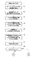
FIGS. 5 and 6 are flowcharts showing a procedure of a driving force distribution process for determining how much the entire required driving force, that is, the driving force required by the driver to the vehicle, is distributed to the
[0030]
In FIG. 5, first, in step S1, the remaining capacity of the
[0031]
That is, the output current and the input current (charging current) of the capacitor detected by the current /
[0032]
CAPAREM = CAPAFULL- (CAPADISH + CAPACHG) (1)
Here, CAPAFULL is a dischargeable amount when the
[0033]
Then, the calculated remaining capacity of the capacitor CAPAREM is corrected by the internal resistance of the
[0034]
In the present embodiment, the remaining capacity of the
[0035]
Next, in step S2, in accordance with the detected remaining capacity, the distribution amount on the
[0036]
FIG. 7 is a diagram illustrating an example of the output allocation ratio setting table, in which the horizontal axis indicates the remaining capacity CAPAREMC of the
[0037]
In the following step S3, the accelerator-throttle characteristic setting table shown in FIG. 8 is searched according to the accelerator opening θAP detected by the
[0038]
In the accelerator-throttle characteristic setting table in this embodiment, as shown in FIG. 8, the accelerator opening θAP is directly used as the command value θTHCOM, but it goes without saying that the present invention is not limited to this.
[0039]
In step S4, a setting table of motor output distribution according to the throttle valve opening shown in FIG. 9 is searched according to the determined throttle valve opening command value θTHCOM, and a distribution ratio PRATIOTH is determined.
[0040]
As shown in FIG. 9, the setting table of the motor output distribution according to the throttle valve opening indicates that the motor output is increased when the throttle valve opening command value θTHCOM is close to full open (for example, 50 degrees or more). Is set.
[0041]
In the present embodiment, the distribution ratio PRATIOTH is determined in accordance with the throttle valve opening command value θTHCOM. However, the present invention is not limited to this, and one or more of the vehicle speed and the engine speed may be determined. May be used as a parameter to determine this distribution ratio.
[0042]
In the following step S5, a target output map shown in FIG. 10 is searched according to the throttle valve opening command value θTHCOM and the engine speed NE to determine a target driving force POWERCOM.
[0043]
Here, the target output map refers to a map for determining a target driving force POWERCOM requested by the driver, and a throttle valve opening command value θTHCOM (the throttle valve opening command value is one pair with the accelerator opening θAP. 1, the target driving force POWERCOM is set according to the accelerator opening θAP) and the engine speed NE.
[0044]
Further, in step S6, a correction term θTHADD of the throttle valve opening for generating the target driving force POWERCOM (that is, the target driving force POWERCOM is generated when the throttle valve opening is set to θTHCOM + θTHADD) is calculated. In step S7, the vehicle state determination map shown in FIG. 11 is searched according to the vehicle speed VCAR detected by the
[0045]
Here, the margin output EXPOWER of the engine is calculated by the following equation (2).
[0046]
EXPOWER = POWERCOM-RUNRST (2)
However, RUNRST refers to the running resistance of the vehicle, and is determined by searching a RUNRST table (not shown) set according to the vehicle speed VCAR. The target driving force POWERCOM and the running resistance RUNRST are set, for example, in units of W (watts).
[0047]
The running state VSTATUS determined by the vehicle speed VCAR and the margin output EXPOWER as described above refers to the assist distribution ratio of the
[0048]
In the following step S8, it is determined whether or not the running state VSTATUS is greater than "0". When VSTATUS> 0, that is, when the vehicle is in the assist state, the process proceeds to step S9 in FIG. That is, when the vehicle is in the deceleration state or the cruise state, the mode is set to the regeneration mode (the deceleration regeneration mode or the cruise charging mode), and the process proceeds to step S12 in FIG.
[0049]
In step S9, the motor required output MOTORPOWER is calculated by the following equation (3).
[0050]
MOTORPOWER = POWERCOM × PRATIO × PRATIOTH × VSTATUS (3)
Next, a MOTORCOM calculation process (FIG. 12) for calculating a motor output command value MOTORCOM according to the requested output MOTORPOWER is executed (step S10).
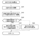
[0051]
In step S41 of FIG. 12, the required output change amount DMPOWER, which is a deviation between the current required output MOTORPOWER calculated in step S9 and the previous required motor output MOTORPOWER (n-1), is calculated by the following equation (4). . (N-1) is added to indicate that it is the previous value.
[0052]
DMPOWER = MOTORPOWER-MOTORPOWER (n-1) (4)
Then, the RMPOWER map is searched according to the required output change amount DMPOWER and the gear position GP, and a reference output change amount RMPOWER corresponding to the upper limit value of the change amount (change rate) per unit time of the motor required output MOTORPOWER is calculated ( Step S42). The RMPOWER map is set such that the reference output change amount RMPOWER increases as the required output change amount DMPOWER increases and the speed ratio (driven side rotation speed / drive side rotation speed) corresponding to the gear position GP increases. Have been. The reference output change amount RMPOWER when the required output change amount DMPOWER is a negative value is set to a negative value.
[0053]
In step S43, it is determined whether or not the absolute value of the required output change amount DMPOWER is greater than the absolute value of the reference output change amount RMPOWER. When | DMPOWER | ≦ | RMPOWER |, the motor output command value MOTORCOM is changed. The request output MOTORPOWER calculated in step S9 is set (step S45). On the other hand, when | DMPOWER |> | RMPOWER |, the motor output command value MOTORCOM is calculated by the following equation (5) (step S44).
[0054]
MOTORCOM = MOTERPOWER (n-1) + RMPOWER ... (5)
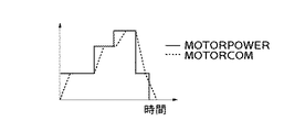
Through steps S43 to S45, the amount of change (current value-previous value) of the motor output command value MOTORCOM is suppressed to the reference output change amount RMPOWER or less. As a result, when the motor required output MOTORPOWER changes as shown by the solid line in FIG. 13, the motor output command value MOTORCOM gradually changes as shown by the broken line in FIG. Further, for example, as shown in FIG. 15A, when the driver of the vehicle depresses the accelerator pedal and the throttle valve is opened, the motor output command value MOTORCOM, that is, the motor output becomes as shown in FIG. Since the motor output gradually changes as shown in the figure and the motor output increases substantially in synchronization with the change in the engine output, the combined driving force of the motor output and the engine output increases smoothly as shown in FIG. Can be prevented.
[0055]
Further, since the reference output change amount RMPOWER is set so as to increase as the speed ratio increases as described above, when the speed ratio is high, the motor output changes quickly, and a desired driving force is obtained early. When the gear ratio is low, the motor output changes at a low rate of change, and torque shock can be avoided.
[0056]
Returning to FIG. 6, in step S11, a correction term (reduced value) θTHASSIST for controlling the target value θTHO of the throttle valve opening in the closing direction according to the motor output command value MOTORCOM calculated in step S10 is calculated. Proceed to step S18.
[0057]
The correction term θTHASSIST is for suppressing the output of the
[0058]
That is, the target value θTHO of the throttle valve opening is determined by the sum of the throttle valve opening command value θTHCOM determined in step S3 and the correction term θTHADD calculated in step S6, and the throttle actuator is determined by the target value θTHO. When the
[0059]
In step S12, it is determined whether or not the current regeneration mode is the deceleration regeneration mode. This determination is performed based on the margin output EXPOWER, and is performed by determining whether EXPOWER <0 (or whether it is smaller than a negative predetermined value near 0). This determination may be made by determining whether or not the change amount DAP of the accelerator opening θAP is smaller than a predetermined negative amount DAPD (in that case, the deceleration regeneration mode is set when DAP <DAPD). It is determined, and when DAP ≧ DAPD, the cruise regeneration mode is determined).
[0060]
In step S12, when the margin output EXPOWER is smaller than 0 (when smaller than the negative predetermined value near 0), the mode is determined to be the deceleration regeneration mode, and the motor request output MOTORPOWER is set to the deceleration regeneration output REGPOWER (step S13). ). Here, the deceleration regeneration output REGPOWER uses a value calculated in a deceleration regeneration processing routine (not shown).
[0061]
In the subsequent step S14, the optimal throttle valve opening target value θTHO in the deceleration regeneration mode, that is, the target value θTHO of the throttle valve opening calculated in the deceleration regeneration processing routine is read and set, and then the process proceeds to step S19.
[0062]
On the other hand, in step S12, when the margin output EXPOWER is a value near 0 (the running state VSTATUS is 0 because the answer in step S8 is negative (NO)), it is determined that the vehicle is in the cruise charging mode. The motor request output MOTORPOWER is set to the cruise charge output CRUISEPOWER (step S15). Here, the cruise charge output CRUISEPOWER uses a value calculated in a cruise charge processing routine (not shown).
[0063]
In the following step S16, the above-described processing of FIG. 12 is executed to calculate the motor output command value MOTORCOM. In step S17, the target value θTHO of the throttle valve opening is set in the opening direction in accordance with the motor output command value MOTORCOM. After calculating the correction term (increase value) θTHSUB for control, the process proceeds to step S18.
[0064]
Here, the reason why the correction term θTHSUB is calculated is exactly the same as the reason why the correction term θTHASSIST is calculated.
[0065]
That is, in the cruise charging mode, the motor request output MOTORPOWER is set to the opposite sign to the motor request output MOTORPOWER in the assist mode. That is, the
[0066]
In step S18, the target value θTHO of the throttle valve opening is calculated by the following equation (6).
[0067]
θTHO = θTHCOM + θTHADD + θTHSUB−θTHASSIST ‥‥ (6)
In a succeeding step S19, it is determined whether or not the target value .theta.THO of the throttle valve opening is equal to or more than a predetermined value .theta.THREF. When .theta.THO <.theta.THREF, it is determined whether or not the intake pipe absolute pressure PBA is equal to or less than a predetermined value PBAREF. (Step S20).
[0068]
When PBA> PBAREF in step S20, the present driving force distribution process is terminated. On the other hand, when θTHO ≧ θTHREF in step S19, or when PBA ≦ PBAREF in step S20, the transmission ratio of the
[0069]
In the state where the process shifts to step S21, the remaining capacity of the
[0070]
Next, the engine control executed by the
[0071]
FIG. 14 is a flowchart showing the overall configuration of the engine control process. This process is executed by the
[0072]
First, various engine operation parameters such as the engine speed NE and the intake pipe absolute pressure PBA are detected (step S131), then the operation state determination processing (step S132), the fuel control processing (step S133), and the ignition timing control processing (step S131) S134) and the DBW control process (step S135) are sequentially executed.
[0073]
That is, while controlling the fuel injection amount and controlling the ignition timing according to the engine speed NE, the intake pipe absolute pressure PBA, and the like, the actual throttle valve opening θTH is calculated by the throttle valve calculated in step S18 in FIG. The drive control of the
[0074]
In the above-described embodiment, step S5 in FIG. 5 corresponds to the target driving force calculating unit, step S9 in FIG. 6 corresponds to the required output calculating unit, and steps S10 and 12 in FIG. 6 correspond to the control unit. I do.
[0075]
Note that the present invention is not limited to the above-described embodiment, and can be implemented in various forms. For example, not only a super capacitor but also a battery may be used as the storage means.
[0076]
Further, in the above-described embodiment, the reference output change amount RMPOWER is calculated according to the required output change amount DMPOWER and the gear position GP in the processing of FIG. 12, but the present invention is not limited to this, and the target driving force POWERCOM may be calculated. , The intake pipe absolute pressure PBA, the change per unit time of the intake pipe absolute pressure PBA, the moving average value of the change per unit time of the throttle valve opening θTH, the required output change DMPOWER, and the gear position GP. The reference output change amount RMPOWER may be calculated according to at least one of the (gear ratio). The amount of change in the target driving force POWERCOM, the absolute pressure PBA in the intake pipe, the amount of change in the absolute pressure PBA in the intake pipe per unit time, the moving average value of the amount of change in the throttle valve opening θTH per unit time, and the required output change DMPOWER are: , Corresponds to the “parameter related to the amount of change in the required output” described in the claims.
[0077]
Further, instead of a so-called DBW type throttle valve, an engine having a throttle valve mechanically linked to a normal accelerator pedal may be used. In this case, the control of the intake air amount according to the motor output may be performed by a passage bypassing the throttle valve and a control valve provided in the middle of the passage. Further, in an engine equipped with an electromagnetically driven intake valve (an electromagnetically driven intake valve, not a cam mechanism), the intake air amount is controlled by changing the opening period of the intake valve. You may.
[0078]
Further, the
[0079]
【The invention's effect】
As described in detail above, according to the present invention, the required output of the motor is calculated in accordance with the target driving force of the vehicle, and the motor is controlled so as to obtain the calculated required output. When the change amount exceeds a predetermined reference value, the change amount of the motor output is set to the predetermined reference value, so that the motor output gradually changes until it reaches a value corresponding to the required output. As a result, the motor output changes almost in synchronization with the change in the engine output that is delayed with respect to the change in the target driving force, so that the combined driving force of the motor output and the engine output changes smoothly, preventing torque shock. can do. In addition, the time delay from the change in the target driving force to the rise of the combined driving force is minimized (that is, equal to or less than a vehicle without driving assistance by a motor) within a range in which torque shock does not occur. Sex can be maintained.Further, according to this configuration, the predetermined reference value increases as the change amount of the required output of the motor increases, so that the motor output is increased or decreased at an appropriate change rate corresponding to the change amount of the required output of the motor. And the vehicle can be driven more smoothly.
[0080]
According to the present invention,Since the rate of change of the motor output is set in accordance with a parameter related to the amount of change of the required output and / or the speed ratio of the transmission, the motor is controlled at an appropriate rate of change corresponding to the amount of change of the required motor output or the speed ratio. The output can be increased or decreased, and the vehicle can be driven more smoothly.
[Brief description of the drawings]
FIG. 1 is a diagram for explaining a schematic configuration of a drive device and a control device for a hybrid vehicle according to an embodiment of the present invention.
FIG. 2 is a diagram showing a configuration of an engine control system.
FIG. 3 is a diagram showing a configuration of a motor control system.
FIG. 4 is a diagram showing a control system of a transmission mechanism.
FIG. 5 is a flowchart illustrating a procedure of a driving force distribution process for determining how much the total required driving force is distributed to the motor and the engine.
FIG. 6 is a flowchart showing a procedure of a driving force distribution process for determining how much the total required driving force is distributed to the motor and the engine.
FIG. 7 is a diagram illustrating an example of an output distribution ratio setting table.
FIG. 8 is a diagram illustrating an example of an accelerator-throttle characteristic setting table.
FIG. 9 is a view showing a setting table of a motor output distribution according to a throttle valve opening;
FIG. 10 is a diagram showing an example of a target output map.
FIG. 11 is a diagram showing an example of a vehicle state determination map.
FIG. 12 is a flowchart of a MOTORCOM calculation process of FIG. 6;
FIG. 13 is a diagram showing a relationship between a motor request output MOTORPOWER and a converted motor output command value MOTORCOM.
FIG. 14 is a flowchart illustrating an overall configuration of an engine control process.
FIG. 15 is a time chart showing changes in vehicle driving force corresponding to changes in throttle valve opening.
[Explanation of symbols]
1 Internal combustion engine
2 Drive shaft
3 Motor
4 Transmission mechanism
5 drive wheels
11 Engine control electronic control unit
12. Motor control electronic control unit (target driving force calculation means, required output calculation means, control means)
13 Power Driving Unit
14. Supercapacitor (power storage means)
15 Management electronic control unit
16 Transmission mechanism control electronic control unit
21 Data bus
Claims (2)
前記車両の運転状態に応じて当該車両の目標駆動力を算出する目標駆動力算出手段と、
前記蓄電された電気エネルギの残容量を算出する残容量算出手段と、
該算出された残容量に応じて、前記目標駆動力における前記モータが出力すべき駆動量の比率である配分率を設定する出力配分設定手段と、
前記目標駆動力及び前記配分率に応じて前記モータの要求出力を算出する要求出力算出手段と、
前記算出された要求出力が得られるように前記モータを制御する制御手段とを備え、
前記制御手段は、前記要求出力の変化量が所定の基準値を超えたときは、前記モータ出力の変化量を前記所定の基準値とし、
前記所定の基準値は、前記要求出力の変化量が増加するほど増加することを特徴とするハイブリッド車両の制御装置。A hybrid vehicle control device comprising: an engine that drives a drive shaft of a vehicle; a motor that assists the drive shaft with electric energy; and a power storage unit that stores the electric energy and supplies power to the motor.
Target driving force calculation means for calculating a target driving force of the vehicle according to the driving state of the vehicle,
Remaining capacity calculating means for calculating the remaining capacity of the stored electric energy,
Output distribution setting means for setting a distribution ratio, which is a ratio of a driving amount to be output by the motor at the target driving force, according to the calculated remaining capacity;
Request output calculating means for calculating a required output of the motor according to the target driving force and the distribution ratio;
Control means for controlling the motor so that the calculated required output is obtained,
When the change amount of the required output exceeds a predetermined reference value, the control unit sets the change amount of the motor output as the predetermined reference value ,
The control device for a hybrid vehicle, wherein the predetermined reference value increases as an amount of change in the required output increases .
前記車両の運転状態に応じて当該車両の目標駆動力を算出する目標駆動力算出手段と、Target driving force calculation means for calculating a target driving force of the vehicle according to the driving state of the vehicle,
前記蓄電された電気エネルギの残容量を算出する残容量算出手段と、Remaining capacity calculating means for calculating the remaining capacity of the stored electric energy,
該算出された残容量に応じて、前記目標駆動力における前記モータが出力すべき駆動量の比率である配分率を設定する出力配分設定手段と、Output distribution setting means for setting a distribution ratio that is a ratio of a drive amount to be output by the motor at the target driving force, according to the calculated remaining capacity;
前記目標駆動力及び前記配分率に応じて前記モータの要求出力を算出する要求出力算出手段と、Request output calculating means for calculating a required output of the motor according to the target driving force and the distribution ratio;
前記算出された要求出力が得られるように前記モータを制御する制御手段と、Control means for controlling the motor such that the calculated required output is obtained,
前記車両の駆動軸と前記エンジン及びモータとの間に設けられた変速機構と、A transmission mechanism provided between the drive shaft of the vehicle and the engine and the motor;
該変速機構の変速比を検出する変速比検出手段とを備え、Speed ratio detecting means for detecting a speed ratio of the speed change mechanism,
前記制御手段は、前記要求出力の変化量が所定の基準値を超えたときは、前記モータ出力の変化量を前記所定の基準値とし、さらに、前記要求出力の変化量に関連するパラメータ及び前記検出した変速比の少なくとも一方に応じて前記モータ出力の変化率を設定することを特徴とするハイブリッド車両の制御装置。When the amount of change in the required output exceeds a predetermined reference value, the control means sets the amount of change in the motor output to the predetermined reference value, and further includes a parameter and a parameter related to the amount of change in the required output. A control device for a hybrid vehicle, wherein the change rate of the motor output is set according to at least one of the detected gear ratios.
Priority Applications (1)
| Application Number | Priority Date | Filing Date | Title |
|---|---|---|---|
| JP2002292705A JP3575763B2 (en) | 2002-10-04 | 2002-10-04 | Hybrid vehicle control device |
Applications Claiming Priority (1)
| Application Number | Priority Date | Filing Date | Title |
|---|---|---|---|
| JP2002292705A JP3575763B2 (en) | 2002-10-04 | 2002-10-04 | Hybrid vehicle control device |
Related Parent Applications (1)
| Application Number | Title | Priority Date | Filing Date |
|---|---|---|---|
| JP34430597A Division JP3380728B2 (en) | 1997-11-28 | 1997-11-28 | Control device for hybrid vehicle |
Publications (2)
| Publication Number | Publication Date |
|---|---|
| JP2003204607A JP2003204607A (en) | 2003-07-18 |
| JP3575763B2 true JP3575763B2 (en) | 2004-10-13 |
Family
ID=27655718
Family Applications (1)
| Application Number | Title | Priority Date | Filing Date |
|---|---|---|---|
| JP2002292705A Expired - Lifetime JP3575763B2 (en) | 2002-10-04 | 2002-10-04 | Hybrid vehicle control device |
Country Status (1)
| Country | Link |
|---|---|
| JP (1) | JP3575763B2 (en) |
Families Citing this family (1)
| Publication number | Priority date | Publication date | Assignee | Title |
|---|---|---|---|---|
| JP5903311B2 (en) * | 2012-03-30 | 2016-04-13 | 本田技研工業株式会社 | Hybrid vehicle |
-
2002
- 2002-10-04 JP JP2002292705A patent/JP3575763B2/en not_active Expired - Lifetime
Also Published As
| Publication number | Publication date |
|---|---|
| JP2003204607A (en) | 2003-07-18 |
Similar Documents
| Publication | Publication Date | Title |
|---|---|---|
| JP3216082B2 (en) | Control device for hybrid vehicle | |
| JP3478723B2 (en) | Control device for hybrid vehicle | |
| JP3847438B2 (en) | Control device for hybrid vehicle | |
| KR100289291B1 (en) | Hybrid Vehicle Control | |
| JP3096446B2 (en) | Control device for hybrid vehicle | |
| JP2843883B2 (en) | Control device for hybrid vehicle | |
| JP3256657B2 (en) | Hybrid vehicle control device | |
| JP3661071B2 (en) | Control device for hybrid vehicle | |
| US6603278B2 (en) | Control system for hybrid vehicle | |
| JP3177153B2 (en) | Control device for hybrid vehicle | |
| JP3699592B2 (en) | Control device for hybrid drive vehicle | |
| JP2000073806A (en) | Control device for hybrid drive vehicle | |
| JP3698220B2 (en) | Control device for hybrid vehicle | |
| JP2005069029A (en) | Controller of internal combustion engine | |
| JP3575763B2 (en) | Hybrid vehicle control device | |
| JP3675627B2 (en) | Control device for hybrid vehicle | |
| JP3380728B2 (en) | Control device for hybrid vehicle | |
| JP3611556B2 (en) | Control device for hybrid vehicle | |
| JPH104607A (en) | Controller of hybrid vehicle | |
| JPH11182276A (en) | Control device for hybrid vehicle | |
| JP3857423B2 (en) | Control device for hybrid drive vehicle | |
| JPH0979061A (en) | Output control device for internal combustion engine | |
| JP2004176725A (en) | Control device of hybrid vehicle |
Legal Events
| Date | Code | Title | Description |
|---|---|---|---|
| A131 | Notification of reasons for refusal |
Free format text: JAPANESE INTERMEDIATE CODE: A131 Effective date: 20040316 |
|
| A521 | Request for written amendment filed |
Free format text: JAPANESE INTERMEDIATE CODE: A523 Effective date: 20040506 |
|
| TRDD | Decision of grant or rejection written | ||
| A01 | Written decision to grant a patent or to grant a registration (utility model) |
Free format text: JAPANESE INTERMEDIATE CODE: A01 Effective date: 20040622 |
|
| A61 | First payment of annual fees (during grant procedure) |
Free format text: JAPANESE INTERMEDIATE CODE: A61 Effective date: 20040702 |
|
| R150 | Certificate of patent or registration of utility model |
Free format text: JAPANESE INTERMEDIATE CODE: R150 |
|
| FPAY | Renewal fee payment (event date is renewal date of database) |
Free format text: PAYMENT UNTIL: 20080716 Year of fee payment: 4 |
|
| FPAY | Renewal fee payment (event date is renewal date of database) |
Free format text: PAYMENT UNTIL: 20090716 Year of fee payment: 5 |
|
| FPAY | Renewal fee payment (event date is renewal date of database) |
Free format text: PAYMENT UNTIL: 20100716 Year of fee payment: 6 |
|
| FPAY | Renewal fee payment (event date is renewal date of database) |
Free format text: PAYMENT UNTIL: 20100716 Year of fee payment: 6 |
|
| FPAY | Renewal fee payment (event date is renewal date of database) |
Free format text: PAYMENT UNTIL: 20110716 Year of fee payment: 7 |
|
| FPAY | Renewal fee payment (event date is renewal date of database) |
Free format text: PAYMENT UNTIL: 20110716 Year of fee payment: 7 |
|
| FPAY | Renewal fee payment (event date is renewal date of database) |
Free format text: PAYMENT UNTIL: 20120716 Year of fee payment: 8 |
|
| FPAY | Renewal fee payment (event date is renewal date of database) |
Free format text: PAYMENT UNTIL: 20120716 Year of fee payment: 8 |
|
| FPAY | Renewal fee payment (event date is renewal date of database) |
Free format text: PAYMENT UNTIL: 20130716 Year of fee payment: 9 |
|
| FPAY | Renewal fee payment (event date is renewal date of database) |
Free format text: PAYMENT UNTIL: 20140716 Year of fee payment: 10 |
|
| EXPY | Cancellation because of completion of term |