JP3575673B2 - Connection structure of shield tunnel segments - Google Patents
Connection structure of shield tunnel segments Download PDFInfo
- Publication number
- JP3575673B2 JP3575673B2 JP16210399A JP16210399A JP3575673B2 JP 3575673 B2 JP3575673 B2 JP 3575673B2 JP 16210399 A JP16210399 A JP 16210399A JP 16210399 A JP16210399 A JP 16210399A JP 3575673 B2 JP3575673 B2 JP 3575673B2
- Authority
- JP
- Japan
- Prior art keywords
- segment
- connection structure
- shield tunnel
- pin insertion
- pin
- Prior art date
- Legal status (The legal status is an assumption and is not a legal conclusion. Google has not performed a legal analysis and makes no representation as to the accuracy of the status listed.)
- Expired - Lifetime
Links
Images


Landscapes
- Lining And Supports For Tunnels (AREA)
Description
【0001】
【発明の属する技術分野】
本発明は、シールドトンネルに使用し、円周方向に隣接するセグメントの接続構造に関する。
【0002】
【従来の技術】
周知の通りシールド機で掘削したトンネルの内周面は複数の円弧状のセグメントでライニングすなわち覆工していた。したがって隣接するセグメントはトンネルの円周方向および軸線方向を連結手段、例えばボルト等で締結している。
【0003】
しかしながら、連結手段による締結作業は例えばボルト、ナットの場合は回転手段でナットやボルトを回転させることは面倒であり、自動化の阻害となる。
【0004】
そのために、図3に示すようにセグメントSの円周方向の接続面Cには溝G又は突部(反対側の接続面)が設けられ、軸線方向の面Aには突起P又は穴(反対側の面)が設けられている。
【0005】
したがって、円周方向は溝Gとその溝Gに係合する突部を係合させて固定し、軸線方向は突起Pと突起Pに係合する穴とを係合させればよい。
【0006】
このようなセグメントSは内周面Iが突起物のない平滑面であり、見栄えがよく、その把持作業は眞空式の把持装置で行われている。
【0007】
すなわち、ボルト、ナットなどの継手の場合、継手の防食の目的、もしくは内面を平滑にする目的から、ボルトボックスを充填するなどの後処理が必要となる。これらを解決する手段として、例えば「ほぞつきセグメント」などセグメントが実用化されているが、これらもセグメントの組立時の形状確保の目的から、仮設部材である「組立てボルト」を設置してあり、内面の平滑や組立てボルトの防食のために後処理が必要となる。このように内周面にボルト等の連結手段がないので、止水作業も比較的に容易である。
【0008】
したがって、かかるセグメントは覆工作業能率がよく、好適に使用できる。しかしながら軸線方向の接続に際して、セグメントSを切羽側から前回設置したセグメントを押し付るので、切羽側のコーナ部Kにおいて隣接するセグメントのコーナ部と間に間隙が生ずるいわゆる目開き現象が生じてしまう。
【0009】
【発明が解決しようとする課題】
したがって本発明の目的は、円周方向および軸線方向の面をそれぞれ凹部凸部とで係合させてセグメントを組立てる際に、コーナ部に目開きを生ずることのないセグメントの接続構造を提供することにある。
【0010】
本発明の他の目的は、作業能率が高く、止水部を最小限にすることができるセグメントの接続構造を提供するにある。
【0011】
【課題を解決するための手段】
本発明によれば、セグメントの円周方向および軸線方向の接続面が凹部および凸部の係合によって連結されるシールドトンネル用セグメントもしくは接続面が平坦な構造のシールドトンネル用セグメントの接続構造において、隣接するセグメント(S1、S2)の接続面のうち一方のセグメント(S1)の接続面(B)の端部から円周方向に延びる突出金物(56)が埋設したプレート(57)に固定されており、その突出金物(56)にはピン挿入穴(60)が設けられ、他方のセグメント(S2)にはピン挿入穴(61)を有する埋込金具(58)が設けられ、それらの両ピン挿入穴(60、61)を合致させてピン(59)が挿入されている。
【0012】
したがって、突出金物のピン挿入穴に埋込金具のピン挿入穴とを合致させてピンを挿入することによってコーナ部の目開きを防止できる。
【0013】
【発明の実施の形態】
以下、図面を参照して本発明の実施の形態を説明する。
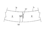
図1、図2において、一方のセグメントS1の接続面Bの端部から円周方向に延びる突出金物56が埋設したプレート57に固定されており、その突出金物56にはピン挿入穴60が設けられている。他方のセグメントS2にはピン挿入穴61を有する埋込金具58が設けられている。したがって両ピン挿入穴60、61を合致させてピン59を挿入すればよい。
なお、ピン59は例えば可撓性のある突出金物56に固定してもよい。
【0014】
【発明の効果】
以上の通り、本発明によれば隣接するセグメントの切羽側の接続面の端部にあらかじめ埋込金具を埋設しておき、ピンを挿入するだけで目開きを防止できる。したがって簡単な手段でしかも作業も容易であるから作業能率がよい。
特に内面が平滑なセグメントは止水作業が少なくてよいので、かかるセグメントに対して好適に実施できる。
【図面の簡単な説明】
【図1】本発明を実施したセグメントを示す端面図。
【図2】図1に示すセグメントが連結される前の状態を示す斜視図。
【図3】従来のセグメントを示す斜視図。
【符号の説明】
S、S1、S2、・・・セグメント
B・・・切羽側の面
P・・・突起
G・・・溝
56・・・突出金物
57・・・プレート
58・・・埋込金具
59・・・ピン
60、61・・・ピン挿入穴[0001]
TECHNICAL FIELD OF THE INVENTION
The present invention relates to a connection structure for circumferentially adjacent segments used in a shield tunnel.
[0002]
[Prior art]
As is well known, the inner peripheral surface of a tunnel excavated by a shield machine has been lined with a plurality of arc-shaped segments. Therefore, adjacent segments are fastened in the circumferential direction and the axial direction of the tunnel by connecting means such as bolts.
[0003]
However, in the case of a bolt or a nut, for example, in the case of a bolt or a nut, it is troublesome to rotate the nut or the bolt by the rotating means, which hinders automation.
[0004]
For this purpose, as shown in FIG. 3, a groove G or a protrusion (an opposite connection surface) is provided on the circumferential connection surface C of the segment S, and a protrusion P or a hole (opposite) is provided on the axial surface A. Side surface) is provided.
[0005]
Therefore, in the circumferential direction, the groove G and the protrusion engaging with the groove G are engaged and fixed, and in the axial direction, the protrusion P and the hole engaging with the protrusion P may be engaged.
[0006]
In such a segment S, the inner peripheral surface I is a smooth surface having no protrusions and has a good appearance, and the gripping operation is performed by a vacuum type gripping device.
[0007]
That is, in the case of a joint such as a bolt or a nut, post-treatment such as filling a bolt box is required for the purpose of preventing corrosion of the joint or smoothing the inner surface. As means to solve these, for example, segments such as "mortise segment" have been put to practical use, but also for the purpose of securing the shape at the time of assembling the segment, a temporary member "assembly bolt" is installed, Post-treatment is required for smoothing the inner surface and preventing corrosion of the assembled bolt. Since there is no connecting means such as bolts on the inner peripheral surface, the water stopping operation is relatively easy.
[0008]
Therefore, such a segment has good lining work efficiency and can be used suitably. However, when connecting in the axial direction, the segment S is pressed against the previously installed segment from the face side, so that a so-called opening phenomenon occurs in which a gap is formed between the corner portion K on the face side and the corner portion of an adjacent segment. .
[0009]
[Problems to be solved by the invention]
Accordingly, it is an object of the present invention to provide a segment connection structure that does not cause openings in corners when assembling the segment by engaging the circumferential and axial surfaces with the concave protrusions, respectively. It is in.
[0010]
Another object of the present invention is to provide a connection structure of segments that has a high work efficiency and can minimize a water stop portion.
[0011]
[Means for Solving the Problems]
According to the present invention, in a connection structure of a shield tunnel segment or a shield tunnel segment in which a connection surface in a circumferential direction and an axial direction of a segment is connected by engagement of a concave portion and a convex portion or a flat connection surface, A protruding metal (56) extending circumferentially from an end of the connection surface (B) of one segment (S1) of the connection surfaces of the adjacent segments (S1, S2) is fixed to the embedded plate (57). The protruding metal part (56) is provided with a pin insertion hole (60), and the other segment (S2) is provided with an embedding fitting (58) having a pin insertion hole (61). The pin (59) is inserted with the insertion holes (60, 61) aligned.
[0012]
Therefore, opening of the corner portion can be prevented by inserting the pin by aligning the pin insertion hole of the protruding metal with the pin insertion hole of the embedding metal fitting.
[0013]
BEST MODE FOR CARRYING OUT THE INVENTION
Hereinafter, embodiments of the present invention will be described with reference to the drawings.
1 and 2, a
Note that the
[0014]
【The invention's effect】
As described above, according to the present invention, it is possible to prevent the opening by simply inserting the embedding metal fitting in advance at the end of the connecting face on the face side of the adjacent segment and inserting the pin. Therefore, the work efficiency is good because the work is easy with simple means.
In particular, a segment having a smooth inner surface requires less water stoppage work, so that the segment can be suitably implemented.
[Brief description of the drawings]
FIG. 1 is an end view showing a segment embodying the present invention.
FIG. 2 is a perspective view showing a state before the segments shown in FIG. 1 are connected.
FIG. 3 is a perspective view showing a conventional segment.
[Explanation of symbols]
S, S1, S2,..., Segment B, face on the face side P, projection G,
Claims (1)
Priority Applications (1)
| Application Number | Priority Date | Filing Date | Title |
|---|---|---|---|
| JP16210399A JP3575673B2 (en) | 1999-06-09 | 1999-06-09 | Connection structure of shield tunnel segments |
Applications Claiming Priority (1)
| Application Number | Priority Date | Filing Date | Title |
|---|---|---|---|
| JP16210399A JP3575673B2 (en) | 1999-06-09 | 1999-06-09 | Connection structure of shield tunnel segments |
Publications (2)
| Publication Number | Publication Date |
|---|---|
| JP2000345795A JP2000345795A (en) | 2000-12-12 |
| JP3575673B2 true JP3575673B2 (en) | 2004-10-13 |
Family
ID=15748119
Family Applications (1)
| Application Number | Title | Priority Date | Filing Date |
|---|---|---|---|
| JP16210399A Expired - Lifetime JP3575673B2 (en) | 1999-06-09 | 1999-06-09 | Connection structure of shield tunnel segments |
Country Status (1)
| Country | Link |
|---|---|
| JP (1) | JP3575673B2 (en) |
Families Citing this family (1)
| Publication number | Priority date | Publication date | Assignee | Title |
|---|---|---|---|---|
| CN115762315B (en) * | 2022-10-31 | 2025-08-12 | 中铁第四勘察设计院集团有限公司 | Device for simulating formation of synchronous grouting shield tail gap |
-
1999
- 1999-06-09 JP JP16210399A patent/JP3575673B2/en not_active Expired - Lifetime
Also Published As
| Publication number | Publication date |
|---|---|
| JP2000345795A (en) | 2000-12-12 |
Similar Documents
| Publication | Publication Date | Title |
|---|---|---|
| CA2002993C (en) | Fluid conduit coupling device | |
| JP2010540872A (en) | Lock elements and bolt fittings | |
| JP3575673B2 (en) | Connection structure of shield tunnel segments | |
| KR20000062114A (en) | Pipe connection structure | |
| JP3310913B2 (en) | Piping cover | |
| JP3962478B2 (en) | Segment joints and segments for tunnel lining work | |
| JP2843889B2 (en) | Concrete segment and joint structure of concrete segment | |
| JP4040445B2 (en) | Fitting | |
| JP4338886B2 (en) | Segment positioning structure | |
| JP4462741B2 (en) | Pipe joint | |
| JPH0571298U (en) | Concrete fittings for concrete segments for tunnels | |
| JP3474388B2 (en) | Segment joint structure | |
| JPH0747509Y2 (en) | Concrete segment | |
| JPH09221992A (en) | Segment connection structure | |
| JPS625113Y2 (en) | ||
| JPH0613876Y2 (en) | Culvert box and gutter block connecting device | |
| JP2001182490A (en) | Segment joining method and apparatus | |
| JP3787637B2 (en) | Assembly bolt fall prevention device for mortise segment | |
| JP3888773B2 (en) | Tunnel segment gripping part lid | |
| JPH10169382A (en) | Connection structure of tunnel segment | |
| JPH0626634Y2 (en) | Joint structure of concrete segment | |
| JP3268110B2 (en) | Segment joint structure | |
| JPS6131118Y2 (en) | ||
| JPH03471Y2 (en) | ||
| JPS59177500A (en) | Method of assembly construction of concrete segment |
Legal Events
| Date | Code | Title | Description |
|---|---|---|---|
| A977 | Report on retrieval |
Free format text: JAPANESE INTERMEDIATE CODE: A971007 Effective date: 20040120 |
|
| A131 | Notification of reasons for refusal |
Free format text: JAPANESE INTERMEDIATE CODE: A131 Effective date: 20040123 |
|
| A521 | Written amendment |
Free format text: JAPANESE INTERMEDIATE CODE: A523 Effective date: 20040301 |
|
| A131 | Notification of reasons for refusal |
Free format text: JAPANESE INTERMEDIATE CODE: A131 Effective date: 20040409 |
|
| A521 | Written amendment |
Free format text: JAPANESE INTERMEDIATE CODE: A523 Effective date: 20040602 |
|
| TRDD | Decision of grant or rejection written | ||
| A01 | Written decision to grant a patent or to grant a registration (utility model) |
Free format text: JAPANESE INTERMEDIATE CODE: A01 Effective date: 20040701 |
|
| A61 | First payment of annual fees (during grant procedure) |
Free format text: JAPANESE INTERMEDIATE CODE: A61 Effective date: 20040701 |
|
| R150 | Certificate of patent or registration of utility model |
Free format text: JAPANESE INTERMEDIATE CODE: R150 |
|
| R250 | Receipt of annual fees |
Free format text: JAPANESE INTERMEDIATE CODE: R250 |