JP3573379B2 - Switch device for bilge pump - Google Patents
Switch device for bilge pump Download PDFInfo
- Publication number
- JP3573379B2 JP3573379B2 JP21590995A JP21590995A JP3573379B2 JP 3573379 B2 JP3573379 B2 JP 3573379B2 JP 21590995 A JP21590995 A JP 21590995A JP 21590995 A JP21590995 A JP 21590995A JP 3573379 B2 JP3573379 B2 JP 3573379B2
- Authority
- JP
- Japan
- Prior art keywords
- diaphragm
- spring receiving
- case
- receiving cylinder
- pump
- Prior art date
- Legal status (The legal status is an assumption and is not a legal conclusion. Google has not performed a legal analysis and makes no representation as to the accuracy of the status listed.)
- Expired - Fee Related
Links
Images


Description
【0001】
【発明の属する技術分野】
本発明は、ダイヤフラムケース内を負圧室および大気圧室に区画するダイヤフラムの周縁部がダイヤフラムケースに支持され、マイクロスイッチに連接されるロッドがダイヤフラムの中央部に固着され、外端を閉じるとともに内端を負圧室に通じさせたばね受け筒が前記ロッドの軸方向に延びてダイヤフラムケースに設けられ、ばね受け筒の外端閉塞部およびダイヤフラム間にコイルばねが縮設され、ビルジポンプの吸入管に通じる管路を接続させる接続管がばね受け筒の側部に設けられるビルジポンプ用スイッチ装置に関する。
【0002】
【従来の技術】
従来、外端を閉じるとともに内端を負圧室に通じさせたばね受け筒がダイヤフラムケースに設けられ、ばね受け筒の外端閉塞部およびダイヤフラム間にコイルばねが縮設されるビルジポンプ用スイッチ装置が、たとえば実開昭57−15052号公報等により既に知られている。
【0003】
【発明が解決しようとする課題】
ところで、ダイヤフラムケース内に形成される負圧室には、ビルジポンプの吸入管からホース等の管路を介して負圧が導入されるものであるが、管路を無理に曲げずにかつ極力短くする等の管路の取りまわし上、ばね受け筒の側部にほぼ直交して設けられた接続管に管路を接続することが要求されることがある。この場合、ビルジポンプの吸入管に連なる管路を流れるビルジには小石や塵が含まれることがあり、ばね受け筒内に配置されているコイルばねと、ばね受け筒内に開口する接続管の内端開口部との間が狭いと、小石や塵等が接続管の内端開口部およびコイルばね間に詰まり、吸入管内の負圧が負圧室に正確に伝わらず、ダイヤフラムの作動が異常となるおそれがある。
【0004】
本発明は、かかる事情に鑑みてなされたものであり、負圧を導く管路が接続される接続管がばね受け筒の側部に連設されるにあたって、小石や塵による詰まりが生じることを防止し、詰まりによる動作不良が生じることを防止し得るようにしたビルジポンプ用スイッチ装置を提供することを目的とする。
【0005】
【課題を解決するための手段】
上記目的を達成するために本発明は、ダイヤフラムケース内を負圧室および大気圧室に区画するダイヤフラムの周縁部がダイヤフラムケースに支持され、マイクロスイッチに連接されるロッドがダイヤフラムの中央部に固着され、外端を閉じるとともに内端を負圧室に通じさせたばね受け筒が前記ロッドの軸方向に延びてダイヤフラムケースに設けられ、ばね受け筒の外端閉塞部およびダイヤフラム間にコイルばねが縮設され、ビルジポンプの吸入管に通じる管路を接続させる接続管がばね受け筒の側部に設けられるビルジポンプ用スイッチ装置において、ばね受け筒の側部には、その一部を外側方に膨らませた膨大部が設けられ、ばね受け筒の内側面に開口するとともにばね受け筒の内端に開口して軸方向に延びる連通溝が前記膨大部により形成され、前記接続管が前記連通溝に通じるようにして前記膨大部に連設されることを特徴とする。
【0006】
【発明の実施の形態】
以下、本発明の実施の形態を、添付図面に示した本発明の一実施例に基づいて説明する。
【0007】
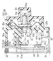
図1ないし図7は本発明の一実施例を示すものであり、図1はビルジポンプに取付けられたスイッチ装置の横断平面図、図2は図1の2−2線断面図、図3は図1の3−3線矢視図、図4は図1の要部拡大図、図5は図1の5−5線拡大断面図、図6は図3の6−6線拡大断面図、図7は図6の7−7線断面図である。
【0008】
先ず図1において、このビルジポンプPのポンプケース11は、合成樹脂により概略円筒状に形成されるとともにその一端がモータMに連結されるポンプケース主体12と、該ポンプケース主体12の他端を閉鎖するカバープレート13とから構成される。而してモータMにはポンプケース主体12の一端に結合されるフランジ14が設けられる。またカバープレート13は、ポンプケース主体12の他端との間にガスケット15を挟んでポンプケース主体12に結合される。
【0009】
図2および図3を併せて参照して、ポンプケース主体12には、モータMの出力軸17が突入するポンプ室16がポンプケース主体12の他端に開口するように形成されており、該ポンプ室16の開口部は前記カバープレート13により閉鎖される。該ポンプ室16の周壁は、図2の右半部において前記出力軸17を中心とする円弧状に形成された周壁半部16aと、図2の左半部において前記出力軸17に対して偏心した円弧状に形成される周壁半部16bとで構成される。このポンプ室16内には、ポンプ室16の周壁に摺接する複数たとえば6本の腕部18a,18a…を有するゴム製のインペラ18が、その側面をカバープレート13の内面に摺接させて収納されるものであり、該インペラ18は、その中心にインサートされたボス19を介して出力軸17に結合される。
【0010】
ポンプケース主体12の側部には、矢印23で示す回転方向へのインペラ18の回転に応じてビルジをポンプ室16内に吸入するための吸入管20と、ポンプ室16からビルジを吐出するための吐出管21とが、水平方向に延びて連設されており、またポンプケース主体12の下部には、船体の適所に取付けられてポンプケース11を支持するための台状の脚部22が設けられる。而して吸入管20には、船底のビルジ貯溜部に連通する吸入ホース24が接続され、吐出管21には船外に開口する吐出ホース25が接続される。
【0011】
ビルジポンプPのポンプケース11には本発明に従って構成されるスイッチ装置が取付けられるものであり、該スイッチ装置は、ポンプケース11におけるカバープレート13に結合されるスイッチボックス26と、該スイッチボックス26内に収納、固定されるマイクロスイッチ27と、スイッチボックス26に結合されるダイヤフラムケース28と、該ダイヤフラムケース28で周縁部を支持されてダイヤフラムケース28内に収納されるダイヤフラム29と、ダイヤフラムケース28およびダイヤフラム29間に設けられるばね30と、ダイヤフラム29の中央部に固着されるとともに前記マイクロスイッチ27に連接されるロッド31とを備える。
【0012】
スイッチボックス26は、ポンプケース主体12の外径にほぼ対応した外径を有して一端を開放した円筒部26aの他端が端壁26bで閉塞されて成る碗状に形成されるものであり、その開口端とカバープレート13の外面との間にガスケット32を介在させるようにしてポンプケース11に結合される。すなわち、スイッチボックス26、ガスケット32、カバープレート13およびポンプケース主体12を、該ポンプケース主体12の周方向に間隔をあけた複数個所たとえば4個所で貫通するスルーボルト33,33…が、モータMのフランジ14に螺合され、各スルーボルト33,33…を締付けることによりスイッチボックス26がポンプケース11に結合されることになる。
【0013】
図4および図5を併せて参照して、スイッチボックス26には、その中心に関して対称にして略90度の範囲で円弧状に形成されて円筒部26aの内方に位置する一対の当接支持部34,34が一体に設けられ、それらの当接支持部34,34の両端は円筒部26aに連設される。而して両当接支持部34,34は、スイッチボックス26がカバープレート13に結合された状態では、ポンプ室16に対応する部分でカバープレート13の外面に当接する。
【0014】
またスイッチボックス26における円筒部26aの内面および両当接支持部34,34の中央部間にわたっては補強リブ35,35がそれぞれ設けられ、それらの補強リブ35,35も、スイッチボックス26がカバープレート13に結合された状態でカバープレート13の外面に当接する。而して、スイッチボックス26がカバープレート13に結合されたときには、スイッチボックス26内に、円筒部26aの内面および両当接支持部34,34で規定されるマイクロスイッチ収納室36が形成されるとともに、両当接支持部34,34および円筒部26aの内面間に4つの空室が形成されることになる。それらの空室の1つはブリーザ室37として機能するものであり、該ブリーザ室37の上部は一方の当接支持部34に設けられた連通溝38を介してマイクロスイッチ収納室36に連通され、またブリーザ室37の下部は、スイッチボックス26における端壁26bに穿設された空気流通孔39により外部に連通される。
【0015】
マイクロスイッチ27は、その外形形状を矩形の函状としてマイクロスイッチ収納室36内に収納、固定されるものであり、スイッチボックス26における端壁26bには、マイクロスイッチ27を嵌合させるようにして横断面略U字状に形成されるとともに先端面を締着面40aとした締着支持部40と、マイクロスイッチ27の該締着支持部40で覆われない一側面の一部に係合する係合支持部41とが突設されるとともに、締着支持部40および係合支持部41で覆われた部分には、先端面を支持面42aとした1あるいは複数の支持部42が突設される。
【0016】
マイクロスイッチ27は、操作子45を突出させる一面27aを支持面42aに当接させるようにして締着支持部40および係合支持部41に嵌合されるものであり、その他面27bには押さえ板43が当接される。而して締着支持部40の締着面40aと支持部42の支持面42aとの間の距離L1 はマイクロスイッチ27の両面27a,27b間の距離L2 よりもわずかに小さく(L1 <L2 )設定される。
【0017】
押さえ板43は、マイクロスイッチ27の他面27bへの当接状態では、複数個所たとえば3個所でマイクロスイッチ27から外側方に突出する複数たとえば3つの締着板部43a,43b,43cを有するように略三角形状に形成されており、各締着板部43a〜43cがねじ部材44…により締着面40aに締着される。
【0018】
マイクロスイッチ27には、係合支持部41よりも外側方に突出する一対の端子板46,47と、押さえ板43に設けられた開口部43dから外方に突出する端子板48とが設けられ、端子板46,48にそれぞれリード線49,50が接続される。而してスイッチボックス26の開口端に設けられた切欠き51にはグロメット52が装着されており、前記両リード線49,50は該グロメット52を水密に貫通して外部に引き出される。
【0019】
ところで,上記マイクロスイッチ27は、モータMに連なる押しボタンスイッチ(図示せず)に並列に接続されるものであり、操作子45に押圧力が作用していない状態で導通状態にあるが、押圧力の作用により操作子45が押し込まれると遮断状態となるものである。
【0020】
図6を併せて参照して、ダイヤフラムケース28は、スイッチボックス26に一体に設けられたケース部53と、該ケース部53との間にダイヤフラム29の周縁部を挟持してケース部53に結合されるケース部材54とで構成される。前記ケース部53は、スイッチボックス26の端壁26bと、該端壁26bの外面に一体に突設される円筒部26cとで外方に開いた皿状に構成されるものであり、ケース部材54はケース部53側に開いた皿状に形成される。而してケース部53における円筒部26cの端部と、ケース部材54の開口端部とは、それらの間にダイヤフラム29の周縁部を挟んだ状態で超音波溶着等により相互に結合される。
【0021】
ダイヤフラムケース28内は、ダイヤフラム29によりケース部53側の大気圧室55と、ケース部材54側の負圧室56とに区画され、スイッチボックス26の端壁26bには、大気圧室55をマイクロスイッチ収納室36に通じさせる透孔57が穿設される。またダイヤフラム29の中央部には、大気圧室55側のロッド31と、負圧室56側のガイドピン58とが、それら31,58でダイヤフラム29を両側から挟むようにして固着されており、透孔57に遊通挿通されたロッド31がマイクロスイッチ27の操作子45に当接される。
【0022】
図7を併せて参照して、ケース部材54には、外端が端壁59aで閉塞されるとともに内端を負圧室56に通じさせたばね受け筒59が、ロッド31およびガイドピン58と同軸にして一体に設けられており、ガイドピン58を囲繞するコイル状であるばね30がダイヤフラム29の中央部とばね受け筒59の外端すなわち端壁59aとの間に縮設される。
【0023】
ばね受け筒59の側部には、その一部を外側方に膨らませた膨大部59bが設けられており、この膨大部59bにより、ばね受け筒59の内側面に開口するとともにばね受け筒59の内端に開口して軸方向に延びる連通溝64が形成され、接続管60が連通溝64に通じるようにして膨大部59bに連設される。一方、ビルジポンプPにおける吸入管20にも接続管61が略直角に連設されており、両接続管60,61にホース等の管路62の両端が接続される。
【0024】
次にこの実施例の作用について説明すると、船底に溜まったビルジの排水にあたって押しボタンスイッチによりビルジポンプPのモータMを作動せしめると、吸入管20で生じた負圧が負圧室56に作用し、ダイヤフラム29がばね31のばね力に抗して負圧室56側に撓み、マイクロスイッチ27の操作子45へのロッド31からの押圧力が解放され、マイクロスイッチ27が導通状態となる。したがって押しボタンスイッチから手を放して該押しボタンスイッチが遮断状態となってもモータMへの電力供給が継続され、ビルジポンプPは作動し続ける。而してビルジがなくなると、吸入管20は空気を吸入することになり、それにより負圧室56の負圧が低下してダイヤフラム29がばね31のばね力により大気圧室55側に復帰し、ロッド31が操作子45を押すことによりマイクロスイッチ27が遮断する。したがってモータMへの電力供給が停止され、ビルジポンプPの作動が停止されることになる。
【0025】
このようなビルジポンプPのスイッチ装置において、ダイヤフラムケース28は、スイッチボックス26に一体に設けられたケース部53と、該ケース部53に結合されるケース部材54とから成るものであり、スイッチボックス26の一部がダイヤフラムケース28の一部となる構成であるので、ダイヤフラムケースおよびスイッチボックスが相互に別体として構成されていた従来のものと比べると部品点数を低減することができる。
【0026】
またスイッチボックス26は、ポンプケース11側に開放した碗状に形成されるとともにその開口端とカバープレート13の外面との間にガスケット32を介在させてポンプケース11に締着されるので、スイッチボックス26を閉じる蓋を不要として防水構造を得ることができ、これによっても部品点数の低減を図ることができる。しかもスイッチボックス26には、ポンプ室16に対応する部分でカバープレート13の外面に当接する当接支持部34,34が設けられているので、カバープレート13が外方側に膨らむことを防止することができ、それによりインペラ18のカバープレート13の内面への摺接状態を確実に維持することができる。その結果、カバープレート13の外方への膨らみを放置していた場合の吸入管20での負圧がたとえば−200mmHgであったのに対し、上述のようにカバープレート13の外方への膨らみを防止した場合には前記負圧がたとえば−300mmHgとなり、ビルジポンプPのポンプ性能を著しく向上することができる。
【0027】
スイッチボックス26内でのマイクロスイッチ27の固定にあたっては、スイッチボックス26に、マイクロスイッチ27の一面27aを当接させる支持面42aを有する支持部42と、締着面40aを先端に有する締着支持部40とが一体に設けられ、マイクロスイッチ27の他面27bに当接された押さえ板43の締着板部43a〜43cが締着面40aに締着されるものであり、支持面42aおよび締着面40a間の距離L1 がマイクロスイッチ27の両面27a,27b間の距離L2 よりも小さく設定されている。したがって押さえ板43に弾性を持たせてマイクロスイッチ27をがた無く確実に固定することが可能となる。
【0028】
ところで、大気圧室55に通じるマイクロスイッチ収納室36が完全密閉状態となるとダイヤフラム29の変位に伴なう容積変化によって大気圧室55の圧力が変化し、負圧動作特性が変化してしまうので、マイクロスイッチ収納室36は水の浸入を防止しつつ大気に連通している必要がある。この観点から、スイッチボックス26内には、マイクロスイッチ27を収納させたマイクロスイッチ収納室36と、マイクロスイッチ収納室36および外部に連通したブリーザ室37とが形成されており、マイクロスイッチ収納室36はブリーザ室37を介して呼吸可能である。しかもブリーザ室37はその上部でマイクロスイッチ収納室36に連通するとともに下部で外部に連通するものであるので、外部からブリーザ室37への浸水があったとしてもブリーザ室37からマイクロスイッチ収納室36側への浸水が極力防止される。
【0029】
さらに吸入管20からダイヤフラムケース28に負圧を導くための管路62を無理に曲げずにかつ極力短くし、またビルジポンプPの全長を短縮するためには、ダイヤフラムケース28に設けられたばね受け筒59の側部に管路62を接続せざるを得ないが、ばね受け筒59内にはコイル状のばね30が収納されており、ばね受け筒59に管路62を接続するためにばね受け筒59に設けられた接続管60のばね受け筒59内への開口端がばね30に近接していると、ビルジ中の小石や塵等がばね受け筒59の内面およびばね30間に詰まってしまい、ダイヤフラム29の正常な作動が困難となるおそれがある。しかるに、ばね受け筒59の内側面には、ばね受け筒59の内端および接続管60間を連通する連通溝64が設けられているので、接続管60の内端開口部とばね30との間に比較的広い空きスペースを設けることが可能となり、ビルジ中の小石や塵等がばね受け筒59の内面およびばね30間に詰まることを極力防止して、ダイヤフラム29の円滑な作動を保証することができる。
【0030】
以上、本発明の実施例を詳述したが、本発明は上記実施例に限定されるものではなく、特許請求の範囲に記載された本発明を逸脱することなく種々の設計変更を行なうことが可能である。
【0031】
【発明の効果】
以上のように本発明によれば、ばね受け筒の内側面に、接続管およびばね受け筒の内端間を連通する連通溝が設けられるので、接続管の内端開口部とコイルばねとの間に比較的広い空きスペースを設けることが可能となり、ビルジ中の小石や塵等が接続管の内端開口部およびコイルばね間に詰まることを極力防止して、詰まりによりダイヤフラムの作動が異常となることを防止することができる。
【図面の簡単な説明】
【図1】ビルジポンプに取付けられたスイッチ装置の横断平面図である。
【図2】図1の2−2線断面図である。
【図3】図1の3−3線矢視図である。
【図4】図1の要部拡大図である。
【図5】図1の5−5線拡大断面図である。
【図6】図3の6−6線拡大断面図である。
【図7】図6の7−7線断面図である。
【符号の説明】
20・・・吸入管
27・・・マイクロスイッチ
28・・・ダイヤフラムケース
29・・・ダイヤフラム
30・・・コイルばね
31・・・ロッド
55・・・大気圧室
56・・・負圧室
59・・・ばね受け筒
59b・・・膨大部
60・・・接続管
62・・・管路
64・・・連通溝
P・・・ビルジポンプ[0001]
TECHNICAL FIELD OF THE INVENTION
According to the present invention, a peripheral portion of a diaphragm that partitions the inside of the diaphragm case into a negative pressure chamber and an atmospheric pressure chamber is supported by the diaphragm case, a rod connected to the microswitch is fixed to a central portion of the diaphragm, and the outer end is closed. A spring case having an inner end communicating with the negative pressure chamber extends in the axial direction of the rod and is provided in the diaphragm case. A coil spring is contracted between the outer end closing portion and the diaphragm of the spring case, and a suction pipe of the bilge pump is provided. The present invention relates to a switch device for a bilge pump in which a connecting pipe for connecting a pipe leading to a spring is provided on a side portion of a spring receiving cylinder.
[0002]
[Prior art]
Conventionally, a bilge pump switch device in which a spring case having an outer end closed and an inner end communicating with a negative pressure chamber is provided in a diaphragm case, and a coil spring is contracted between an outer end closing portion of the spring case and the diaphragm. For example, it is already known, for example, from Japanese Utility Model Laid-Open No. 57-15052.
[0003]
[Problems to be solved by the invention]
By the way, in the negative pressure chamber formed in the diaphragm case, a negative pressure is introduced from the suction pipe of the bilge pump through a pipe such as a hose, but the pipe is not forcibly bent and is as short as possible. Due to the arrangement of pipes, it is sometimes required to connect the pipes to a connection pipe provided substantially orthogonally to the side of the spring receiving cylinder. In this case, the bilge flowing through the pipe line connected to the suction pipe of the bilge pump may contain pebbles and dust, and the coil spring disposed in the spring receiving cylinder and the connecting pipe opening in the spring receiving cylinder may be used. If the gap between the end opening is small, pebbles and dust will clog between the inner end opening of the connection pipe and the coil spring, and the negative pressure in the suction pipe will not be accurately transmitted to the negative pressure chamber, causing abnormal operation of the diaphragm. Could be.
[0004]
The present invention has been made in view of such circumstances, and when a connecting pipe to which a conduit for guiding negative pressure is connected is connected to a side portion of a spring receiving cylinder, clogging due to pebbles and dust occurs. It is an object of the present invention to provide a bilge pump switch device capable of preventing a malfunction due to clogging.
[0005]
[Means for Solving the Problems]
In order to achieve the above object, according to the present invention, a diaphragm that partitions the inside of a diaphragm case into a negative pressure chamber and an atmospheric pressure chamber is supported by the diaphragm case, and a rod connected to a microswitch is fixed to a central portion of the diaphragm. A spring receiving cylinder having an outer end closed and an inner end connected to the negative pressure chamber extends in the axial direction of the rod and is provided in the diaphragm case, and the coil spring is compressed between the outer end closing portion of the spring receiving cylinder and the diaphragm. In a bilge pump switch device in which a connection pipe for connecting a pipe line leading to a suction pipe of the bilge pump is provided on a side of the spring receiving cylinder, a part of the side of the spring receiving cylinder is bulged outward. An enlarged portion is provided, and a communication groove that opens on the inner surface of the spring receiving cylinder and opens at the inner end of the spring receiving cylinder and extends in the axial direction is formed by the enlarged portion. Is formed, said connection tube is characterized in that it is provided continuously to the ampulla so as to communicate with the communication groove.
[0006]
BEST MODE FOR CARRYING OUT THE INVENTION
Hereinafter, an embodiment of the present invention will be described based on an embodiment of the present invention shown in the accompanying drawings.
[0007]
1 to 7 show an embodiment of the present invention. FIG. 1 is a cross-sectional plan view of a switch device mounted on a bilge pump, FIG. 2 is a sectional view taken along line 2-2 of FIG. 1, and FIG. 1 is a view taken along the line 3-3, FIG. 4 is an enlarged view of a main part of FIG. 1, FIG. 5 is an enlarged sectional view of the line 5-5 in FIG. 1, and FIG. 7 is a sectional view taken along line 7-7 in FIG.
[0008]
First, in FIG. 1, a
[0009]
2 and 3, a
[0010]
A
[0011]
A switch device constructed according to the present invention is attached to the
[0012]
The
[0013]
4 and 5, the
[0014]
[0015]
The
[0016]
The
[0017]
When the
[0018]
The
[0019]
The
[0020]
Referring also to FIG. 6, the
[0021]
The inside of the
[0022]
7, the
[0023]
On the side of the
[0024]
Next, the operation of this embodiment will be described. When the motor M of the bilge pump P is operated by a push button switch to drain the bilge accumulated on the bottom of the ship, the negative pressure generated in the
[0025]
In such a switch device of the bilge pump P, the
[0026]
The
[0027]
When the
[0028]
By the way, when the micro
[0029]
Further, in order to minimize the length of the
[0030]
As described above, the embodiments of the present invention have been described in detail. However, the present invention is not limited to the above embodiments, and various design changes can be made without departing from the present invention described in the claims. It is possible.
[0031]
【The invention's effect】
As described above, according to the present invention, a communication groove communicating between the connecting pipe and the inner end of the spring receiving cylinder is provided on the inner surface of the spring receiving cylinder, so that the inner end opening of the connecting pipe and the coil spring are connected to each other. It is possible to provide a relatively large empty space between them, minimizing the possibility of pebbles and dust in the bilge clogging between the opening at the inner end of the connection pipe and the coil spring, and the clogging may cause abnormal operation of the diaphragm. Can be prevented.
[Brief description of the drawings]
FIG. 1 is a cross-sectional plan view of a switch device attached to a bilge pump.
FIG. 2 is a sectional view taken along line 2-2 of FIG.
FIG. 3 is a view taken in the direction of arrows 3-3 in FIG. 1;
FIG. 4 is an enlarged view of a main part of FIG. 1;
FIG. 5 is an enlarged sectional view taken along line 5-5 of FIG. 1;
FIG. 6 is an enlarged sectional view taken along line 6-6 in FIG. 3;
FIG. 7 is a sectional view taken along line 7-7 of FIG. 6;
[Explanation of symbols]
20,
59b ···
Claims (1)
Priority Applications (1)
| Application Number | Priority Date | Filing Date | Title |
|---|---|---|---|
| JP21590995A JP3573379B2 (en) | 1995-08-24 | 1995-08-24 | Switch device for bilge pump |
Applications Claiming Priority (1)
| Application Number | Priority Date | Filing Date | Title |
|---|---|---|---|
| JP21590995A JP3573379B2 (en) | 1995-08-24 | 1995-08-24 | Switch device for bilge pump |
Publications (2)
| Publication Number | Publication Date |
|---|---|
| JPH0963438A JPH0963438A (en) | 1997-03-07 |
| JP3573379B2 true JP3573379B2 (en) | 2004-10-06 |
Family
ID=16680266
Family Applications (1)
| Application Number | Title | Priority Date | Filing Date |
|---|---|---|---|
| JP21590995A Expired - Fee Related JP3573379B2 (en) | 1995-08-24 | 1995-08-24 | Switch device for bilge pump |
Country Status (1)
| Country | Link |
|---|---|
| JP (1) | JP3573379B2 (en) |
-
1995
- 1995-08-24 JP JP21590995A patent/JP3573379B2/en not_active Expired - Fee Related
Also Published As
| Publication number | Publication date |
|---|---|
| JPH0963438A (en) | 1997-03-07 |
Similar Documents
| Publication | Publication Date | Title |
|---|---|---|
| CA2398258A1 (en) | Filter assembly for a vacuum cleaner | |
| US5876599A (en) | Compact in-tank fuel filter and module | |
| JP3573379B2 (en) | Switch device for bilge pump | |
| KR950011856A (en) | Scroll Compressor | |
| JP3573378B2 (en) | Switch device for bilge pump | |
| JPH01176792U (en) | ||
| JP2001286715A (en) | Filter element and filter apparatus | |
| US11808268B2 (en) | Stick pump assembly | |
| JP3476398B2 (en) | Oil strainer mounting structure for automatic transmission | |
| CN108930618B (en) | Air filter for internal combustion engine | |
| JP3685893B2 (en) | Electromagnetic reciprocating air pump | |
| JPH07293496A (en) | Submerged pump | |
| CN215949799U (en) | Novel toy water pump | |
| CN218177492U (en) | Built-in electric air pump | |
| JP2000130327A (en) | Hermetically sealed electric compressor | |
| CN220423995U (en) | Tooth-flushing device | |
| KR200154075Y1 (en) | Suction pipe for upright cleaner | |
| JP2854277B2 (en) | Engine intake system | |
| JPS6023508Y2 (en) | Support structure of fuel pump in fuel tank with built-in fuel pump | |
| JPH0277367U (en) | ||
| JPH0114307Y2 (en) | ||
| JPS6039519Y2 (en) | Pump automatic operation device | |
| JPH04321891A (en) | Discharge water pipe connecting structure in outboard motor of the like | |
| JPS59108885A (en) | Portable air pump | |
| CN115988825A (en) | Liquid driving assembly |
Legal Events
| Date | Code | Title | Description |
|---|---|---|---|
| TRDD | Decision of grant or rejection written | ||
| A01 | Written decision to grant a patent or to grant a registration (utility model) |
Free format text: JAPANESE INTERMEDIATE CODE: A01 Effective date: 20040616 |
|
| A61 | First payment of annual fees (during grant procedure) |
Free format text: JAPANESE INTERMEDIATE CODE: A61 Effective date: 20040625 |
|
| R150 | Certificate of patent or registration of utility model |
Free format text: JAPANESE INTERMEDIATE CODE: R150 |
|
| FPAY | Renewal fee payment (event date is renewal date of database) |
Free format text: PAYMENT UNTIL: 20080709 Year of fee payment: 4 |
|
| FPAY | Renewal fee payment (event date is renewal date of database) |
Free format text: PAYMENT UNTIL: 20080709 Year of fee payment: 4 |
|
| FPAY | Renewal fee payment (event date is renewal date of database) |
Free format text: PAYMENT UNTIL: 20090709 Year of fee payment: 5 |
|
| FPAY | Renewal fee payment (event date is renewal date of database) |
Free format text: PAYMENT UNTIL: 20100709 Year of fee payment: 6 |
|
| FPAY | Renewal fee payment (event date is renewal date of database) |
Free format text: PAYMENT UNTIL: 20100709 Year of fee payment: 6 |
|
| FPAY | Renewal fee payment (event date is renewal date of database) |
Free format text: PAYMENT UNTIL: 20110709 Year of fee payment: 7 |
|
| FPAY | Renewal fee payment (event date is renewal date of database) |
Free format text: PAYMENT UNTIL: 20120709 Year of fee payment: 8 |
|
| FPAY | Renewal fee payment (event date is renewal date of database) |
Free format text: PAYMENT UNTIL: 20130709 Year of fee payment: 9 |
|
| R250 | Receipt of annual fees |
Free format text: JAPANESE INTERMEDIATE CODE: R250 |
|
| LAPS | Cancellation because of no payment of annual fees |