JP3572232B2 - Kneading granulator - Google Patents
Kneading granulator Download PDFInfo
- Publication number
- JP3572232B2 JP3572232B2 JP36394599A JP36394599A JP3572232B2 JP 3572232 B2 JP3572232 B2 JP 3572232B2 JP 36394599 A JP36394599 A JP 36394599A JP 36394599 A JP36394599 A JP 36394599A JP 3572232 B2 JP3572232 B2 JP 3572232B2
- Authority
- JP
- Japan
- Prior art keywords
- kneading
- kneading tank
- impeller
- inner peripheral
- blades
- Prior art date
- Legal status (The legal status is an assumption and is not a legal conclusion. Google has not performed a legal analysis and makes no representation as to the accuracy of the status listed.)
- Expired - Fee Related
Links
Images


Description
【0001】
【発明の属する技術分野】
本発明は、粘土塊等の原材を小塊粒体に造粒成形し、或いは原材にセメント等の凝固剤を混入して小塊粒体に造粒成形する混練造粒装置に関するものであり、粘土塊にセメントを混入して小塊粒体とした場合は、海での埋設用、各種の体積増量用或いはコンクリート骨材等に使用されるものである。
【0002】
【従来の技術】
窯業からの粘土廃材や建築廃材などの原材はそのままでは沿岸での埋め立て材やコンクリート骨材等に使用できないためセメントや凝固剤でそれらの原材を固化させる必要があり、従来では、一対の回転軸を対向回転させて該回転軸に取り付けた多数の羽根の回転で原材と凝固剤とを混練しながら小塊粒体に造粒成形する二軸式混練機が利用されていたのである。
また、フイルタープレスで成形された粘土板を小粒体に造粒する場合も二軸式混練機が使用されていたのである。
【0003】
これによると、小塊粒体が迅速に造粒成形されるが、軟質状態の被混練物が壁面に付着して固化することが多く、この固形体が成長すると、これに羽根が衝突して摩耗、損傷するため、羽根による凝固剤と原材の混練及び被混合物の裁断機能に支障をきたし、その結果、造立された粒体は大きさが不均一で、凝固剤と原材の混合も不均質で良質の塊粒体が得られない課題を有している。
又、上記損傷等による羽根の交換作業や、壁面に付着固化した固形体の除去作業を頻繁に行わねばならず、この作業に手間、時間を要し、甚だ面倒であると共に、その作業の度に混練機を運転中止せねばならず、塊粒体の製造効率が悪いといった問題が生じている。
【0004】
【発明が解決しようとする課題】
そこで本発明は、被混練物が壁面に付着して固化成長することを阻止し、羽根の破損を防止すると共に、均一な粒度で均質な塊粒体を得ることを目的とするものである。
【0005】
【課題を解決するための手段】
本発明は、上記課題に鑑み、切刃を有する羽根を設けた羽根車と、円弧状の湾曲面を有する曲がり羽根を設けた羽根車とを混練槽内に回転自在に設け、該混練槽の内周面と羽根車との隙間を狭小と成し、前記2種の羽根を有する羽根車による剪断、圧延、折り畳み及び圧縮作用等により、被混練物を均一な粒度で均質な塊粒体を得る。
又、混練槽を羽根車を取付けた回転軸に対し、その軸線方向で相対的に往復移動自在に設けることにより、羽根が混練槽内周面に付着した被混練物を掻き落とす様にして、上記課題を解決する。
【0006】
【発明の実施の形態】
以下本発明の一実施例を図面に基づいて説明する。
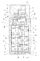
図1〜図4で示す形態例において、1は本発明に係る混練造粒機の固定機体であり、該固定機体1の前部に所定容積を有する断面凹形の混練槽収容部2を設けると共に、該混練槽収容部2の後部に駆動部基台3を設けている。
尚、本形態例において、混練槽収容部2は、上方を開口したものを示したが、実際には、その開口部は、図示しない天蓋にて被覆されている。
【0007】
混練槽収容部2の内周には、可撓性、弾性を有するプラスチックゴム製の混練槽4を収容配置している。
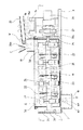
この混練槽4は、周壁(前後左右側壁)5、5a…及び底部6を有すると共に、図2に示す様に、その左右側壁5、5a上端に外向きフランジ7を突設した金属製の取付帯8に固着している。
そして、混練槽収容部2の左右側壁2a、2b上端に外向きに突設したフランジ9に上記フランジ7を上下対向させている。
【0008】
混練槽4のフランジ7下部には、その長さ方向に渡って複数の軸受ブラケット10を固着してコロ11を回転自在に支持し、混練槽収容部2の上端フランジ9上に転動配置している。
これにより、混練槽収容部2の上端フランジ9に沿って混練槽4が前後方向に移動自在に支持される。
又、図2に示す如く、底部6の横手方向の中央部は、少し中高部12となって、底部6の左右を円弧状に湾曲させている。
そして、中高部12の裏面に、その長手(図2において、奥行き)方向に渡り複数のコロ13を設け、該コロ13に対応する様に、混練槽収容部2の中央部に断面略三角山状の突帯レール14を突設し、該突帯レール14の頂部にコロ13を転動配置している。
又、基台3上には、混練槽4を前後動させる油圧シリンダ15が設置され、そのシリンダロッド15aの先端部を、混練槽4の後壁5d上端に立設した基盤16に固着しており、油圧シリンダ15の駆動で混練槽4が前後に進退移動する様に成している。
【0009】
又、混練槽4の底部6前方には、排出孔17を透設し、該排出孔17に連通する排出シュート18を混練槽収容部2の前壁2c下部に設置している。
更に、混練槽4の後方上部には、供給シュート19が設置され、該供給シュート19の上方には、粘土濾滓Wの搬送コンベア20及びセメントCの供給ホッパ20aを設けている。
【0010】
混練槽4内には、切刃21aを有する複数の羽根21を設けた羽根車22と、円弧状の湾曲面23aを有する複数の曲がり羽根23を設けた羽根車24とを回転自在に設けている。
この羽根車22、24は、混練槽4内の左右に平行配置した一対の回転軸25、26の夫々に交互に取付けられている。
又、回転軸25、26は、混練槽4の前後壁5c、5dを挿通して混練槽収容部2の前後に渡って架設して成り、回転軸25、26の後端は、混練槽収容部2の後壁2dを貫通して基台3上に突出させ、該基台3上で回転軸25、26の夫々に軸着した歯車27、28を噛合し、一方の回転軸25を基台3上に設置したギヤードモータ29に連繋させて駆動軸としている。
そして、一方の回転軸25の歯車27を他方の回転軸26の歯車28より大径にして回転比を異にし、他方の回転軸26の回転を速くしている。
尚、回転軸25、26は、混練槽収容部2内の前端部と基台3上に設けた軸受30、30aにて回転自在に支持されており、回転軸25、26の回転比率は適宜に設定している。
又、回転軸25、26は、前部を若干下方へ傾斜させており、これに対応して混練槽4の底部6も前部を若干下方へ傾斜する様に成している(図3参照)。
又、本実施例では、回転軸25、26が2軸のものを示したが、単軸、又は3本以上の回転軸を左右方向に並設した多軸であっても良い。
【0011】
羽根車22、24は、その中心に設けたボス31より羽根21、23を放射状に突設して成り、ボス31を回転軸25、26に嵌合固定している。
羽根車22に設けた羽根21は、図5に示す様に、先端方に向けて弓なりに湾曲させ、その湾出側に切刃21aを設けると共に、先端部21bを屈曲している。
又、羽根車24に設けた羽根23は、図6に示す様に、矩形板を円弧状に湾曲形成し、湾曲面23aを外方へ指向する様に成している。
又、混練槽4の内周面5、5a…、6と羽根車22、24との隙間S、即ち羽根車22における羽根21の先端部21bと内周面5、5a…、6、羽根車24における羽根23の湾曲面23aと内周面5、5a…、6の隙間Sを狭小と成している。
【0012】
そして、羽根車22の羽根21では、その切刃21aで主に被混練物(濾滓W及びセメントC)WCを剪断し、先端部21bと混練槽4の内周面5、5a…、6との間で圧縮する様に成している。
羽根車24の羽根23では、主に、その湾曲面23aと混練槽4の内周面5、5a…、6との間の被混練物WCを圧縮、圧延及び折り畳みする様に成している。
又、図1、4に示す様に、左右の回転軸25、26に夫々固着した羽根車22、24は、羽根車22、24の左右相互の前後間に食い込んだ状態で配置し、図2に示す様に、夫々の羽根21、23の先端を相互に他方の回転軸25、26側に近接させている。
実験によると、羽根21、23の先端と他方の回転軸25、26側との間隙は1〜2cmが最適であった。
【0013】
この形態例によると、フイルタープレスで脱水濾過された粘土濾滓Wが搬送コンベア20で運ばれて供給シュート19から混練槽4の後端に落下され、同時に供給シュート19にセメントCが供給ホッパ20aから供給され、モータ29の駆動による羽根車22、24の羽根21、23の対向回転によって羽根21、23の間や混練槽4の内周面5、5a…、6との間で、剪断、圧延、折り畳み、圧縮されながら混練されて次第に塊状となる。
更に、羽根車22、24の回転によって羽根21、23と混練槽4の内周面5、5a…、6との間を転動しながら固化して塊粒体W1となり、混練槽4の下方傾斜した前端部の排出孔17より落下して排出シュート18から排出される。
得られる塊粒体W1は、羽根21、23と混練槽4の内周面5、5a…、6との隙間を直径とする大きさである。
【0014】
この際、混練槽4の内周面5、5a…、6において、羽根車22、24の前後の間隔に対応した部位に、被混練物WCが付着し固化しようとするが、シリンダ15が常時前後に往復駆動して、混練槽収容部2内に支持されている混練槽4を回転軸25、26に対し軸方向前後で相対移動させているので、混練槽4の内周面5、5a…、6に付着した被混練物WCが大きく成長する前に、混練槽4に対し相対的に前後する羽根21、23により掻き落とされたり、混練槽4の振動により滑落する。
又、混練槽4が可撓性、弾性を有する材質であることから、羽根21、23に押圧されて被混練物WCが内周面5、5a…、6に必要以上に押し付けられて外側に撓曲しても、羽根21、23が被混練物WCより離れた後、内周面5、5a…、6が弾性復帰する時の弾力により、内周面5、5a…、6から飛散、飛去する。
尚、混練槽4の進退移動距離は前後の羽根車22、24の間隔の半分以上あれば良く、通常は10〜15cm移動すれば良い。
又、この混練槽4の進退移動は常時移動していることが望ましいが、断続的に進退移動してもよく、原材に合わせて選択すれば良い。
【0015】
又、被混練物WCが回転軸25、26側に飛散してボス31に付着することもあるが、各回転軸25、26の羽根21、23が相互にその前後間に食い込んで、羽根21、23の端部が回転軸25、26側に近接すると共に、各回転軸25、26の羽根21、23が異なる速度で回転するため、各羽根21、23を他方の回転軸25、26側の全外周部に広い範囲で近接する様に回転させられ、回転軸25、26の相互の羽根21、23が、回転軸25、26(ボス31表面)に付着した被混練物WCを硬化する前に迅速に掻き上げて脱落させる。
【0016】
【発明の効果】
要するに本発明は、混練槽4内に2種の羽根車22、24を回転自在に設け、該羽根車22、24と混練槽4の内周面5、5a…、6との隙間Sを狭小と成し、羽根車22の羽根21には切刃21aを設けて成るので、被混練物WCを剪断して混合し、又羽根車24には円弧状の湾曲面23aを設けて成るので、主に、その湾曲面23aと混練槽4の内周面5、5a…、6との間で被混練物WCを圧縮、圧延及び折り畳みする様に混練し、被混練物WC中の水分を均一に分散させると共に、気泡を極力外部へ排除した均一混合を成すことができる。
この様に、羽根車22、24の羽根21、23の回転によって、羽根21、23の間や混練槽4の内周面5、5a…、6との間で、被混練物WCは剪断、圧延、折り畳み、圧縮されながら極めて均一な混合が成されて次第に塊状と成すことが出来、羽根21、23と混練槽4の内周面5、5a…、6との隙間Sを直径とした均一な粒度で均質な塊粒体W1を得ることができる。
【0017】
又、混練槽4を羽根車22、24を取付けた回転軸25、26に対し、その軸線方向で相対的に往復移動自在に設けたので、混練槽4の内周面5、5a…、6に付着した被混練物WCを成長させることなく、混練槽4に対し相対的に前後する羽根21、23により掻き落とすことや、混練槽4の振動により滑落させられ、その結果的、羽根21、23の欠損、破損を防止できる。
【0018】
又、混練槽4は、羽根車22、24の外周位置で被混練物WCが摺接する内周面5、5a…、6をゴム等の弾性材で形成すると共に、該内周面5、5a…、6を可撓変位できる様に支持したので、羽根21、23によって被混練物WCが内周面5、5a…、6に必要以上に押し付けられても、その後の内周面5、5a…、6の弾性復帰による弾力で、被混練物WCが飛散、飛去等して内周面5、5a…、6にこびりついたり、蓄積固化することがないため、羽根車22、24の損傷を未然に防止できる。
【0019】
又、羽根車22、24を多軸で回転自在に支持し、この回転軸25、26間においては、夫々の羽根21、23を相互に他方の回転軸25、26の羽根21、23の前後間に配置すると共に、夫々の羽根21、23の先端が相互に他方の回転軸25、26側に近接する様に各回転軸25、26に取付けたので、回転軸25、26相互の羽根21、23により、回転軸25、26側に付着した被混練物WCを掻き取ることができ、しかも各回転軸25、26の回転比率を異にしたので、夫々羽根21、23が他方の回転軸25、26側の全外周部に近接して広い範囲で付着した被混練物WCを掻き取ることができ、このため回転軸25、26への固形化した被混練物WCの付着固化を防止して羽根21、23の破損を防止できる等その実用的効果甚だ大である。
【図面の簡単な説明】
【図1】本発明の一形態例の平面図である。
【図2】図1のAーA断面図である。
【図3】図1のBーB断面図である。
【図4】図3のCーC拡大断面図である。
【図5】羽根の拡大斜視図である。
【図6】羽根の拡大斜視図である。
【符号の説明】
4 混練槽
5、5a… 内周面
6 内周面
21 羽根
21a 切刃
22 羽根車
23 羽根
23a 湾曲面
24 羽根車
25 回転軸
26 回転軸
S 隙間
WC 被混練物[0001]
TECHNICAL FIELD OF THE INVENTION
The present invention relates to a kneading and granulating apparatus for granulating and shaping a raw material such as a clay lump into small agglomerates or mixing and mixing a raw material with a coagulant such as cement to form a small agglomerate. In the case where small aggregates are obtained by mixing cement into clay ingots, they are used for embedding in the sea, for increasing the volume of various kinds, or as concrete aggregate.
[0002]
[Prior art]
Raw materials such as clay waste materials and construction waste materials from the ceramics industry cannot be used as such as coastal landfills or concrete aggregates, so it is necessary to solidify those materials with cement or coagulant. A twin-screw kneader that granulates and forms small agglomerates while kneading a raw material and a coagulant by rotating a number of blades attached to the rotating shaft by rotating the rotating shaft in opposition was used. .
Also, when a clay plate formed by a filter press is granulated into small granules, a twin-screw kneader has been used.
[0003]
According to this, the small lumps and granules are quickly granulated and formed, but the material to be kneaded in a soft state often adheres to the wall surface and solidifies. When the solid body grows, the blades collide with the solid body and grow. The abrasion and damage impairs the kneading of the coagulant and raw material by the blades and the cutting function of the mixture. As a result, the formed granules are not uniform in size, and the mixing of the coagulant and raw material is also difficult. There is a problem that a homogeneous and high-quality agglomerate cannot be obtained.
In addition, the work of replacing the blades due to the above-mentioned damage and the work of removing the solid matter adhered to the wall surface must be performed frequently, and this work is time-consuming, time-consuming, extremely troublesome, and requires In addition, the operation of the kneading machine must be stopped, which causes a problem that the production efficiency of the agglomerates is poor.
[0004]
[Problems to be solved by the invention]
Accordingly, an object of the present invention is to prevent the material to be kneaded from adhering to the wall surface and solidifying and growing, to prevent damage to the blades, and to obtain a uniform mass having a uniform particle size.
[0005]
[Means for Solving the Problems]
In view of the above problems, the present invention provides an impeller provided with a blade having a cutting blade and an impeller provided with a curved blade having an arcuate curved surface in a kneading tank so as to be rotatable. The gap between the inner peripheral surface and the impeller is made small, and the mass to be kneaded is formed into a uniform agglomerate with a uniform particle size by shearing, rolling, folding, compressing, and the like by the impeller having the two types of blades. obtain.
Also, by providing the kneading tank relative to the rotating shaft on which the impeller is mounted so as to be able to reciprocate relatively in the axial direction, the blades scrape off the material to be kneaded attached to the inner peripheral surface of the kneading tank, Solution to the Problems
[0006]
BEST MODE FOR CARRYING OUT THE INVENTION
An embodiment of the present invention will be described below with reference to the drawings.
In the embodiment shown in FIGS. 1 to 4,
In the present embodiment, the
[0007]
A
The
The flange 7 is vertically opposed to the
[0008]
A plurality of
Thereby, the
As shown in FIG. 2, the center of the bottom 6 in the lateral direction is slightly middle and high, and the left and right sides of the bottom 6 are curved in an arc shape.
A plurality of
A
[0009]
A
Further, a
[0010]
In the
The
The rotating
The diameter of the
The rotating
In addition, the
In this embodiment, the
[0011]
The
As shown in FIG. 5, the
Further, as shown in FIG. 6, the
The gap S between the inner
[0012]
The
The
Also, as shown in FIGS. 1 and 4, the
According to the experiment, the gap between the tips of the
[0013]
According to this embodiment, the clay filter cake W which has been dewatered and filtered by the filter press is conveyed by the
Further, by the rotation of the
The mass L1 obtained has a size in which a gap between the
[0014]
At this time, on the inner
Further, since the
The moving distance of the
It is desirable that the
[0015]
The kneaded material WC may be scattered on the
[0016]
【The invention's effect】
In short, according to the present invention, two kinds of
In this way, the rotation of the
[0017]
Since the
[0018]
In the
[0019]
Further, the
[Brief description of the drawings]
FIG. 1 is a plan view of one embodiment of the present invention.
FIG. 2 is a sectional view taken along line AA of FIG.
FIG. 3 is a sectional view taken along the line BB of FIG. 1;
FIG. 4 is an enlarged sectional view taken along the line CC of FIG. 3;
FIG. 5 is an enlarged perspective view of a blade.
FIG. 6 is an enlarged perspective view of a blade.
[Explanation of symbols]
4 Kneading
Claims (4)
Priority Applications (1)
| Application Number | Priority Date | Filing Date | Title |
|---|---|---|---|
| JP36394599A JP3572232B2 (en) | 1999-12-22 | 1999-12-22 | Kneading granulator |
Applications Claiming Priority (1)
| Application Number | Priority Date | Filing Date | Title |
|---|---|---|---|
| JP36394599A JP3572232B2 (en) | 1999-12-22 | 1999-12-22 | Kneading granulator |
Publications (2)
| Publication Number | Publication Date |
|---|---|
| JP2001179073A JP2001179073A (en) | 2001-07-03 |
| JP3572232B2 true JP3572232B2 (en) | 2004-09-29 |
Family
ID=18480591
Family Applications (1)
| Application Number | Title | Priority Date | Filing Date |
|---|---|---|---|
| JP36394599A Expired - Fee Related JP3572232B2 (en) | 1999-12-22 | 1999-12-22 | Kneading granulator |
Country Status (1)
| Country | Link |
|---|---|
| JP (1) | JP3572232B2 (en) |
Families Citing this family (2)
| Publication number | Priority date | Publication date | Assignee | Title |
|---|---|---|---|---|
| JP5182001B2 (en) * | 2008-02-29 | 2013-04-10 | 株式会社リコー | Toner production method and toner granulator |
| CN111962293B (en) * | 2020-08-18 | 2022-10-21 | 浙江曙丰毛纺织科技股份有限公司 | Processing technology of blended wool graphene wool fabric |
-
1999
- 1999-12-22 JP JP36394599A patent/JP3572232B2/en not_active Expired - Fee Related
Also Published As
| Publication number | Publication date |
|---|---|
| JP2001179073A (en) | 2001-07-03 |
Similar Documents
| Publication | Publication Date | Title |
|---|---|---|
| CN105558214A (en) | Shearing/mixing tool | |
| CN104494007A (en) | Recycling method of waste and old hard foamed plastics and production line thereof | |
| JP3572232B2 (en) | Kneading granulator | |
| CN116351303A (en) | Raw material proportioning device and process for aquatic feed premix additive | |
| JP3631939B2 (en) | Kneading granulator | |
| CN213260323U (en) | Concrete mixing plant discharge apparatus | |
| CN112892351A (en) | Sea salt compounded mite removing preparation method and equipment | |
| CN210022013U (en) | Kneading mixer for producing silicon carbide ceramic products | |
| CN210045206U (en) | Compound fertilizer granulator | |
| JP2000176302A (en) | Mixer for crushing and mixing | |
| JP3456844B2 (en) | Horizontal twin-screw kneading granulator | |
| JP2000210548A (en) | Biaxial type continuous mixer | |
| CN210385773U (en) | Formula granulation machine is swayd with kind to food | |
| JP3363598B2 (en) | Mass scraping feeder | |
| JP2000238030A (en) | Shredding and mixing mixer | |
| WO2007010877A1 (en) | Granulating method, granulating machine, and method of manufacturing block by using burned ash | |
| JP2562116B2 (en) | Crusher | |
| JP3478921B2 (en) | Agglomerate manufacturing equipment | |
| JP4610112B2 (en) | Mixer | |
| KR100788717B1 (en) | Manufacture device for granule | |
| CN220802954U (en) | Functional coating's dispersion granulation equipment | |
| CN213966455U (en) | Wet granulator | |
| CN220780204U (en) | Wet granulator | |
| CN219463693U (en) | Magnetic material screening device for feed opening of extruder | |
| CN215086934U (en) | Granulator with switchable dry method and wet method |
Legal Events
| Date | Code | Title | Description |
|---|---|---|---|
| TRDD | Decision of grant or rejection written | ||
| A01 | Written decision to grant a patent or to grant a registration (utility model) |
Free format text: JAPANESE INTERMEDIATE CODE: A01 Effective date: 20040615 |
|
| A61 | First payment of annual fees (during grant procedure) |
Free format text: JAPANESE INTERMEDIATE CODE: A61 Effective date: 20040628 |
|
| R150 | Certificate of patent or registration of utility model |
Ref document number: 3572232 Country of ref document: JP Free format text: JAPANESE INTERMEDIATE CODE: R150 Free format text: JAPANESE INTERMEDIATE CODE: R150 |
|
| FPAY | Renewal fee payment (event date is renewal date of database) |
Free format text: PAYMENT UNTIL: 20080702 Year of fee payment: 4 |
|
| R250 | Receipt of annual fees |
Free format text: JAPANESE INTERMEDIATE CODE: R250 |
|
| FPAY | Renewal fee payment (event date is renewal date of database) |
Free format text: PAYMENT UNTIL: 20090702 Year of fee payment: 5 |
|
| R250 | Receipt of annual fees |
Free format text: JAPANESE INTERMEDIATE CODE: R250 |
|
| FPAY | Renewal fee payment (event date is renewal date of database) |
Free format text: PAYMENT UNTIL: 20100702 Year of fee payment: 6 |
|
| R250 | Receipt of annual fees |
Free format text: JAPANESE INTERMEDIATE CODE: R250 |
|
| FPAY | Renewal fee payment (event date is renewal date of database) |
Free format text: PAYMENT UNTIL: 20110702 Year of fee payment: 7 |
|
| R250 | Receipt of annual fees |
Free format text: JAPANESE INTERMEDIATE CODE: R250 |
|
| FPAY | Renewal fee payment (event date is renewal date of database) |
Free format text: PAYMENT UNTIL: 20120702 Year of fee payment: 8 |
|
| R250 | Receipt of annual fees |
Free format text: JAPANESE INTERMEDIATE CODE: R250 |
|
| FPAY | Renewal fee payment (event date is renewal date of database) |
Free format text: PAYMENT UNTIL: 20130702 Year of fee payment: 9 |
|
| R250 | Receipt of annual fees |
Free format text: JAPANESE INTERMEDIATE CODE: R250 |
|
| R250 | Receipt of annual fees |
Free format text: JAPANESE INTERMEDIATE CODE: R250 |
|
| R250 | Receipt of annual fees |
Free format text: JAPANESE INTERMEDIATE CODE: R250 |
|
| R250 | Receipt of annual fees |
Free format text: JAPANESE INTERMEDIATE CODE: R250 |
|
| R250 | Receipt of annual fees |
Free format text: JAPANESE INTERMEDIATE CODE: R250 |
|
| R250 | Receipt of annual fees |
Free format text: JAPANESE INTERMEDIATE CODE: R250 |
|
| R250 | Receipt of annual fees |
Free format text: JAPANESE INTERMEDIATE CODE: R250 |
|
| LAPS | Cancellation because of no payment of annual fees |