JP3567673B2 - Fixing device and image forming method - Google Patents
Fixing device and image forming method Download PDFInfo
- Publication number
- JP3567673B2 JP3567673B2 JP11252497A JP11252497A JP3567673B2 JP 3567673 B2 JP3567673 B2 JP 3567673B2 JP 11252497 A JP11252497 A JP 11252497A JP 11252497 A JP11252497 A JP 11252497A JP 3567673 B2 JP3567673 B2 JP 3567673B2
- Authority
- JP
- Japan
- Prior art keywords
- release agent
- fixing
- sheet
- agent supply
- roll
- Prior art date
- Legal status (The legal status is an assumption and is not a legal conclusion. Google has not performed a legal analysis and makes no representation as to the accuracy of the status listed.)
- Expired - Lifetime
Links
Images


Landscapes
- Fixing For Electrophotography (AREA)
Description
【0001】
【発明の属する技術分野】
本発明は、未定着カラートナー像を有する転写体を加熱部材および加圧部材よりなる定着部材を用いて定着する工程を有する画像形成方法およびそのための定着装置を備えた電子写真複写機、ファクシミリ、プリンタ等の電子写真プロセスを利用する画像形成装置に関する。
【0002】
【従来の技術】
従来、電子写真プロセスを利用した複写機等においては、転写体上に形成された未定着トナー像を定着して永久画像にする必要があり、その定着法として溶剤定着方式、圧力定着方式および加熱定着方式等が知られている。しかしながら、上記の溶剤定着方式および圧力定着方式は環境問題、定着性能等に欠点を有しており、共に広く実用化されていないのが現状である。したがって未定着トナー像の定着には、一般に加熱によってトナーを溶融させ、転写体上に付着させる加熱定着方式が最も広く採用されている。
【0003】
この加熱定着方式としては、少なくとも一方を加熱した一対のロール、すなわち、加熱ロール及び加圧ロール間に、一定圧力を加え、未定着トナー像を有する転写体を通過させて定着を行う加熱ロール方式が知られており、この方式は他の加熱定着装置を用いる場合に比して、低電力、かつ定着部での紙づまりによる発火の危険性の少ないこと等の利点があることから、従来最も広く使用されている定着方式である。
【0004】
加熱ロール方式における、加熱ロールとしては、円筒状芯金の表面にシリコーンゴムまたはフッ素ゴム等の耐熱性弾性体を被覆したもの、およびポリテトラフロロエチレン(PTFE)またはテトラフロロエチレン−パーフロロアルキルビニルエーテル共重合体(PFA)等の耐熱性樹脂を被覆したものが使われている。一方、加圧ロールとしては、上記加熱ロールと加圧接触した時に、或る接触幅を持たせるように円筒状芯金の表面にシリコーンゴム、フッ素ゴム等の耐熱弾性体を被覆したもの、および上記耐熱弾性体の上にポリテトラフロロエチレン(PTFE)またはテトラフロロエチレン−パーフロロアルキルビニルエーテル共重合体(PFA)等の耐熱性樹脂を被覆したものが使われている。
【0005】
しかしながら、この加熱ロール方式を用いた場合、転写体上の未定着トナーと上記加熱ロール表面の耐熱弾性体の離型性が悪いために、転写体上の未定着トナーの一部が加熱ロールに転写され、そのトナーが転写体の後端または次に通紙する転写体に再転写されて転写体を汚染するという、いわゆるオフセット現象が発生したり、転写体上の未定着トナーが接着剤の役目をして転写体が加熱ロールに巻き付き、紙づまりを起こすという問題が発生する。
【0006】
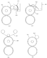
そこで、これらの問題の発生を防止するために、一般にはシリコーンオイル等を離型剤として加熱ロール表面に塗布することが行われている。離型剤を塗布するための離型剤供給装置としては、図4(a)〜(d)に示されるものが知られている。
【0007】
1)離型剤保管用容器から離型剤をフェルト61を通じて、ゴム硬度タイプAデュロメーターで20〜50のシリコーンゴムからなるピックアップロール62に塗布し、そのピックアップロールに接触した同じくゴム硬度タイプAデュロメーターで20〜50のシリコーンゴムからなるドナーロール63によって加熱ロール60に離型剤を塗布するドナーロール方式(図4(a))。
【0008】
この方式は、300センチストークス(cs)程度の低粘度シリコーンオイルを供給するのに適しているため、現在、カラー複写機に広く使用されている。それは次の理由からである。すなわち、カラー画像においては、光沢度の高いトナー定着像の形成が必要となるために、定着時のトナーの溶融粘度が低いものを使用しており、したがって、離型剤であるシリコーンオイルが低粘度でなければ、トナーが加熱ロールにオフセットするからである。
【0009】
しかしながら、この方式では、経時的に加熱ロールに接するドナーロールに、トナーや紙粉が堆積し、離型剤の供給に筋状のムラが発生しやすく、コピー画像に筋状の光沢ムラ等の画像欠陥が発生すること、およびトナーや紙粉の堆積物が加熱ロールに常に接することにより加熱ロールの離型性が低下して、ロールの寿命が短くなること等の問題点がある。さらに、この方式では、加熱ロールに離型剤の供給を均一に行うためには、離型剤の供給量が多くなる。離型剤の供給量が多いことによる問題点として、まず、離型剤のタンクを必要とすることがあげられる。また、両面コピー時などでは、複写機の中の搬送ロール、感光体または転写部材にコピー上の離型剤が移行し、用紙搬送不良や、画像欠陥を引き起こすという問題がある。この離型剤の多量供給の引き起こす問題を、供給量を減ずることにより対処すると、今度は離型剤供給ムラの発生という問題が生じる。特開平6−195011号公報に開示された発明は、これらの問題を解決するために、離型剤を吸収する粒子を有するクリーニング部材を使用するものであるが、未だ十分なものではない。
【0010】
2)離型剤を含浸させた不織布64を加熱ロール60に圧接させて表面に離型剤を塗布するウエブ方式(図4(b))。
この方式は、10000cs程度の高粘度のシリコーンオイルを微少量供給する場合に適しており、現在、白黒複写機に広く使用されている。白黒用トナーはその結着樹脂の分子量が高いことやワックスを含有することによりトナー自体の離型性が優れている。したがって、カラートナーとは異なり高粘度のシリコーンオイルの使用によっても離型性に問題は生じない。しかしながら、この方式を白黒用トナーに適用した場合、離型剤の供給量が少ないことによる加熱ロールの磨耗の点で問題があり、また、カラートナーに適用した場合、カラートナーの離型に必要な低粘度シリコーンオイルを不織布に含浸させて、長期にわたり保持させることが困難であり、しみ出てくる現象であるオイルこぼれが生じる。これを防ぐには、10000cs程度の高粘度のシリコーンオイルを使用することが必要となり、その場合には離型性を満足させることができないことになる。さらには、この方式では、不織布の繊維状の凹凸により、離型剤の供給が筋状のムラになりやすいという欠点もある。
【0011】
特開平6−3999号公報には、この方式での離型剤オイル保持性を改善するために、不織布にオイル保持層を設けることが提案されている。しかしながら、この場合、不織布の吸油性には限界があり、また、離型剤の供給がスジ状のムラになりやすいという欠点がある。
【0012】
3)離型剤保管用容器65よりフェルト等の不織布66を用いて加熱ロール60表面に離型剤を塗布するWick&ブレード方式(図4(c))。
4)内部に離型剤を封入させた離型剤供給ロール67を加熱ロール60の外周面に圧接させて表面に離型剤を塗布するオイルしみだしロール方式(図4(d))。
これらの方式には、コピー枚数が増えるに従って加熱ロールに微量にオフセットしたトナーや紙紛が堆積し、離型剤供給不足や、供給量のムラが生じるという欠点がある。接触型の離型剤供給部材表面に堆積した汚れは、加熱ロールに常に押圧されるので、加熱ロールの表面をも汚染し、加熱ロール表面の離型性を劣化させ、加熱ロールの使用寿命を縮めるという問題がある。
【0013】
以上のように、従来の接触型の離型剤供給装置では、離型剤供給量のムラ、供給不足、カラートナーの離型に適した低粘度の離型剤を供給した場合のオイルこぼれ、供給量の増加のためのタンクスペースの問題、供給量過剰による複写機内パーツ汚染等の問題、およびそれによって生じる離型不良、コピー画上の離型剤オイル筋による画像欠陥、光沢度ムラ、加熱ロールの使用寿命の短縮、複写機の大型化、複写機内パーツの使用寿命の短縮等の問題点を抱えていた。
【0014】
【発明が解決しようとする課題】
本発明は、従来の技術における上記のような欠点を改善し、または除去することを目的としてなされたものである。すなわち、本発明は、離型剤供給装置を備えた定着部材を有する定着装置に関してなされたものであって、その目的は、コピー画像上の離型剤オイル筋等の画像欠陥、定着部材表面の離型性低下、離型剤供給量不足による巻き付きによる紙づまり等の問題の発生を防ぎ、加熱部材および加圧部材の磨耗の起こらない、高画質で、信頼性の高い定着装置を提供することにある。本発明の他の目的は、離型剤オイル筋および光沢度ムラのない高画質のカラーコピー画像を長期にわたり形成することができる画像形成方法を提供することにある。
【0015】
【課題を解決するための手段】
本発明者等は、加熱部材と加圧部材とからなる定着部材を有する定着装置において、加熱部材と加圧部材の少なくともいずれか一方の表面に、離型剤を均一に安定して供給することが可能な離型剤供給装置を設けることにより、上記目的を達成することができることを見出し、本発明を完成するに至った。
【0016】
本発明の定着装置は、加熱部材および加圧部材よりなる定着部材と、離型剤供給装置を有し、その離型剤供給装置が、耐熱性ベースシートと、離型剤を含有する離型剤保持層とからなる離型剤供給シートを、該離型剤保持層が加熱部材および加圧部材の一方に当接するように供給するものであって、該離型剤保持層が、アスカーC硬度30以下のシリコーンゴムよりなる1〜500g/m2 の坪量の弾性体層よりなり、該離型剤が25℃で100ないし5000csの粘度のシリコーンオイルからなり、該離型剤供給シートの離型剤保持量が、弾性体層の坪量の10分の1ないし2倍の範囲であることを特徴とする。
【0017】
本発明の画像形成方法は、潜像保持体上に潜像を形成する工程、該潜像を現像剤を用いて現像する工程、形成されたトナー像を転写体上に転写する工程、加熱部材および加圧部材よりなる定着部材を用いて転写体上のトナー像を定着する工程を有するものであって、上記定着する工程が、耐熱性ベースシートと、アスカーC硬度30以下のシリコーンゴムよりなる1〜500g/m2 の坪量の弾性体層より形成された、離型剤として25℃で100ないし5000csの粘度のシリコーンオイルを含有する離型剤保持層とからなる離型剤供給シートを、該離型剤保持層が加熱部材および加圧部材の一方に当接するように供給して定着を行うものであって、該離型剤供給シートの離型剤保持量を弾性体層の坪量の10分の1ないし2倍の範囲にして定着を行うことを特徴とする。
【0018】
【発明の実施の形態】
図1は、本発明の定着装置の一実施例を示すものであって、概略の構成図である。定着部材は加熱ロール1と加圧ロール2とから構成されており、両ロール間を未定着トナーを担持した転写体4が通過するように構成されている。加熱ロール1は、その内部に加熱ランプ11を備えた金属コア12に、弾性体層13および表面層14を設けた構造を有し、また、加圧ロール2は、その内部に加熱ランプ21を備えた金属コア22に、弾性体層23および表面層24を設けた構造を有している。加熱ロールの側には、離型剤供給装置3が設けられている。離型剤供給装置3は、離型剤供給シート31、離型剤供給シートの巻付け用シャフト32、巻付け用シャフトから引き出された離型剤供給シートを加熱ロールに接触させるための押圧ロール33、加熱ロールと接触した後の離型剤供給シートを巻き取る巻き取りシャフト34、および1〜10mm/毎分の速度で離型剤供給シートの巻き取りを行う制御手段35とから構成されている。本発明における加熱ロール1と加圧ロール2の表面層を構成する材料としては、シリコーンゴム、フッ素ゴム、ポリテトラフロロエチレン(PTFE)およびテトラフロロエチレン−パーフロロアルキルビニルエーテル共重合体(PFA)等のフッ素樹脂が使用できるが、耐磨耗性の観点から、フッ素ゴムおよびフッ素樹脂が好ましく使用できる。
【0019】
本発明において使用する離型剤供給シートは、耐熱性ベースシートおよび離型剤を保持するための離型剤保持層とから構成されている。耐熱性ベースシートは、融点が200℃以上の耐熱性を有するシート状のものであれば、特に限定されることはなく、如何なるものでも使用できる。例えば、芳香族ポリアミド繊維、ポリアミド繊維、ポリフェニレンスルファイド繊維、ポリエステル繊維等からなる不織布(ウエブ)を用いることができる。また、ポリイミドフィルム等のフィルム状物を用いることもできる。これらシートの厚さは、シートの屈曲性の観点から0.1mm以下であることが好ましく、また、強度の観点から0.01mm以上であることが好ましい。
【0020】
離型剤保持層は、ゴム弾性体を有するもので、シリコーンゴムが使用される。シリコーンゴムとしては、シリコーンRTVゴムを用いるのが好ましい。シリコーンRTVゴムは、Si−OH、Si−OR、Si−H、Si−CH=CH2 等の反応基をもつシロキサンを触媒により架橋してゴム弾性体としたものであって、付加型、縮合型のいずれの硬化機構のものでも用いることができる。
【0021】
本発明において、離型剤保持層に用いるシリコーンゴムは、ゴム硬度がアスカーC硬度で30以下であり、特に5〜30の範囲にあるものが好ましい。アスカーC硬度で30以下のシリコーンゴムは、シリコーンオイル等の離型剤により膨潤して、それを吸収し、保持する点において優れており、塗布量に対し充分な量の低粘度の離型剤をこぼれを生じることなく保持することを可能にする。アスカーC硬度で30より硬いゴムの場合には、フィラー含有量が多いか、またはシリコーンゴムの架橋密度が高いために、離型剤を保持できる量が不足し、塗布量不足となる。ここで、アスカーC硬度とは、日本ゴム協会規格SRIS 0101により求められる硬度を意味する。
【0022】
アスカーC硬度で5〜30のシリコーンゴムは、硬度が通常ロールに用いるようなタイプAデュロメータで30〜60の硬度を持つシリコーンゴムに比較して、その硬度が柔らかいため、それを用いた離型剤供給シートは、最表面層の磨耗が起きた時にも均一に加熱ロールに接することが可能であり、したがって、離型剤の供給ムラが発生せず、コピー上の離型剤による筋(オイルすじ)の発生を防ぐことができる。また、アスカーC硬度で5〜30のシリコーンゴムを用いると、加熱ロールまたは加圧ロールの表面における離型性の低下が生じ難く、これらロールの寿命を長くすることができる。これは、離型剤の供給が均一であることが一つの理由であるが、さらに、アスカーC硬度で5〜30のシリコーンゴムに離型剤を含浸させた状態では、液状の離型剤を多量に含んだ状態でシリコーンゴムが膨潤しているために、加熱ロール及び加圧ロールからの紙粉やトナー等の汚れが、シリコーンゴム層内部に取り込まれる現象が起こり、加熱または加圧ロールに接触しつづける汚れの量が実質的に減少することも理由の一つと考えられる。
【0023】
アスカーC硬度30より硬いゴムを用いると、磨耗が起きた時にその磨耗の形状に起因して離型剤の供給ムラが発生し、コピー上にオイルすじ等の画像欠陥が生じる。また、加熱ロールからの汚れが離型剤供給シートの最表面層に溜まってロールに接触しつづけ、ロール表面の離型性の低下によりロールの寿命が短くなる。
【0024】
本発明において、離型剤保持層の坪量は、1〜500g/m2 であることが必要であり、5〜200g/m2 であることが好ましく、さらに好ましくは10〜100g/m2 である。坪量が1g/m2 より小さい時は、離型剤保持層がロール表面や耐熱性ベースシートの凸凹を吸収して変形することができなくなり、離型剤の供給ムラが発生する。坪量が500g/m2 より大きいと、離型剤供給シートを巻物状に格納する際に大きくなりすぎて作業上不都合が生じる。
【0025】
また、離型剤供給シートの離型剤保持量Yは離型剤保持層の坪量Xg/m2 に対して、Y=X/10〜2Xg/m2 の範囲、すなわち、弾性体層の坪量の10分の1ないし2倍の範囲であるのが好ましい。離型剤保持量が弾性体層の坪量の2倍より多いと、離型剤保持層から離型剤がしみだしてしまい、オイルこぼれが発生する。また、弾性体層の坪量の1/10より小さいと、加熱ロールへの離型剤塗布量が不足し、耐オフセット性および定着部材表面の離型性の維持が困難になる。
【0026】
本発明において使用する離型剤としては、シリコーンオイルを用いることができる。シリコーンオイルとしては、ジメチルシリコーンオイル、フェニルメチルシリコーンオイル、アルキル変性シリコーンオイル、フロロシリコーンオイル、カルボキシル変性シリコーンオイル、ポリエーテル変性シリコーンオイル、アミノ変性シリコーンオイル、メルカプト変性シリコーンオイル、ジメチルシリコーンオイルのメチル基の一部を、ポリオキシアルキレン基、アミノ基または長鎖アルキル基で置換した変性シリコーンオイルを用いることができ、これらの混合体であってもよい。
【0027】
上記シリコーンオイルは、25℃で100ないし5000csの粘度のものが使用され、200から1000csのものが好ましい。従来の技術に関して述べたように、トナーの離型性の観点からは、シリコーンオイルの粘度が低い方が望ましく、5000csより高い粘度のシリコーンオイルの場合には、それ自体が粘着性を示し、トナーオフセットを発生してしまう。100csより粘度の低いシリコーンオイルの場合には、揮発性があるために、表面温度が100ないし200℃の定着部材に接触して使用することが難しくなる。
【0028】
本発明における定着装置の定着部材は、図1に示すような加熱ロールと加圧ロールとよりなるものの他に、加熱ロールと加圧側にベルトを用いたもの、加圧ロールと加熱側にベルトを用いたもの、加熱側と加圧側の両方にベルトを用いたもの等、従来公知の定着器の定着部材を用いることができる。
【0029】
図2は、本発明の定着装置の他の実施例の模式的断面図である。図2の定着装置は、加熱側と加圧側の両方にベルトを用いたものであって、加熱側には加熱装置19が設けられており、そしてベルト15は、弾性体ロール16、ガイドロール17および18に張架され、矢印方向に移動するようになっている。また、加圧側のベルト25は、ガイドロール26、27および28に張架され、矢印方向に移動するようになっている。加熱側のベルトおよび加圧側のベルトに接するように、それぞれ離型剤供給装置3aおよび3bが設けられている。これら離型剤供給装置は、図1に示したものと同様の構造を有するものであって、離型剤供給シート31aおよび31b、離型剤供給シートの巻付け用シャフト32aおよび32b、巻付け用シャフトから引き出された離型剤供給シートをベルトに接触させるための押圧ロール33aおよび33b、ベルトと接触した後の離型剤供給シートを巻き取る巻き取りシャフト34aおよび34b、および1〜10mm/毎分の速度で離型剤供給シートの巻き取りを行う制御手段35aおよび35bとから構成されている。未定着トナーを担持した転写体4は、ベルト15とベルト25との間に挿入され、両ベルト間で加熱押圧されて定着が行われるように構成されている。なお、5はクリーニングロールである。
【0030】
図3は、本発明の定着装置を用いた画像形成装置の概略構成図である。この画像形成装置において、感光体ドラム108の周囲には、帯電器107と、現像器109〜112を備えた現像装置と、転写コロトロン115を備えた転写ドラム113が配設されており、上部には照明装置101、カラーCCD103、画像処理装置104、レーザーダイオード105より構成されるレーザー光学系106が設けられており、さらに図1に示す構造の定着装置116が設けられている。
【0031】
この画像形成装置を用いて画像形成を行うためには、感光体ドラム108の表面を帯電器107によって帯電させた後、レーザー光学系によって原稿102の色分解像を照射して静電潜像を形成し、次いで現像装置により所定のカラートナー像を形成する。この操作を各色ごとに繰り返して、感光体ドラム上に4つのトナー(シアン、マゼンタ、イエローおよび黒)よりなるカラートナー像を形成する。次いで、転写ドラム113上の転写紙114に一括して転写した後、定着装置116によって加熱定着される。
【0032】
次に、本発明の画像形成方法について説明する。本発明において、潜像保持体としては、電子写真感光体および誘電記録体等、静電潜像が形成されるものが使用され、公知の方法によって静電潜像が形成される。次いで、潜像保持体上に形成された静電潜像は、現像剤を用い、公知の現像方法によって顕像化される。形成されたトナー像は、紙等の転写体上に、例えば転写帯電器等の手段によって転写され、次いで定着工程において定着される。本発明において、定着は、上記の定着装置によって行われる。すなわち、離型剤として25℃で100ないし5000csの粘度のシリコーンオイルを用い、耐熱性シートからなる耐熱性ベースシートと、アスカーC硬度30以下のシリコーンゴムよりなる坪量1〜500g/m2 の弾性体層よりなる離型剤保持層とによって構成された離型剤供給シートを、離型剤保持層が加熱部材および加圧部材の一方に当接するように供給し、離型剤供給シートの離型剤保持量を弾性体層の坪量の10分の1ないし2倍の範囲にして定着を行う。
【0033】
この場合、離型剤塗布量の制御は、離型剤保持量Yの設定と定着部材と接触する離型剤供給シートの巻き取り速度の制御により主として行われる。巻き取り速度は、特に限定されるものではないが、通常1〜3mm/分程度である。その場合、ステップモータなどの速度制御が簡便な駆動源と巻き取りシャフトとを連動させて、巻き取り速度の可変制御を行ってもよい。例えば、巻き取りシャフトに巻き取ったシートの径を検知する手段や、巻き取り量の履歴データから、巻き取りシャフトの回転速度数を一定にするのではなく、巻き取り速度が一定となるように制御してもよい。また、経時的に微妙に劣化する定着部材表面の離型性の変化をあらかじめ実験等により把握し、離型性を補うように、巻き取り速度をあげて離型剤塗布量を増加させてもよい。さらには、コピー枚数、コピー速度、画像密度、用紙/OHPフィルム等、転写体の種類等により変化する定着条件に合わせて、巻き取り速度を変化させ、離型剤塗布量の微量制御を行ってもよい。
【0034】
定着部材からのカラートナーの離型性および定着部材の離型性を維持するための離型剤塗布量の最低量は0.1ないし1mg/A4程度であるが、本発明によれば、離型剤供給装置により離型剤塗布量を0.1ないし1mg/A4の範囲に調整して均一に塗布することが可能になる。この離型剤塗布量は、従来均一に塗布するために要求される離型剤塗布量の1/10から1/100である。
【0035】
【実施例】
以下に本発明の実施例について説明する。
【0036】
実施例A−1
(離型剤供給シートの作製方法)
耐熱性アラミド繊維不織布(ノーメックス、厚さ70μm、デュポン社製)を耐熱性ベースシートとして用い、その不織布に液状シリコーンゴム(KE1225(触媒量8%)、アスカーC硬度30、信越化学社製)を耐熱性ベースシート面に対して10g/m2 (X=10)の坪量になるように真空中で脱気含浸させ、次いで液状シリコーンゴムを硬化させた。形成されたシートに、300csのジメチルシリコーンオイルを5g/m2 含浸させて離型剤供給シートを得た。(坪量X=10g/m2 、離型剤保持量Y=X/2)
この離型剤供給シートを巻付け用シャフトであるアルミニウムパイプに巻付け、図1に示すような構成の定着装置Aに装着した。
【0037】
実施例A−2
(離型剤供給シートの作製方法)
耐熱性アラミド繊維不織布(ノーメックス、厚さ70μm、デュポン社製)を耐熱性ベースシートとして用い、その不織布に液状シリコーンゴム(KE1225(触媒量8%)、アスカーC硬度30、信越化学社製)を耐熱性ベースシート面に対して500g/m2 (X=500)の坪量になるように真空中で脱気含浸させ、次いで液状シリコーンゴムを硬化させた。形成されたシートに、300csのジメチルシリコーンオイルを50g/m2 含浸させて離型剤供給シートを得た。(坪量X=500g/m2 、離型剤保持量Y=X/10)
この離型剤供給シートを巻付け用シャフトであるアルミニウムパイプに巻付け、図1に示すような構成の定着装置Aに装着した。
【0038】
実施例A−3
(離型剤供給シートの作製方法)
耐熱性ポリイミドフィルム(厚さ10μm)を耐熱性ベースシートとして用い、そのフィルムに液状シリコーンゴム(KE1225(触媒量6%)、アスカーC硬度10、信越化学社製)を耐熱性ベースシート面に対して5g/m2 の坪量になるような厚さで被覆し、真空中で脱気し、液状シリコーンゴムを硬化させた。形成されたシートに、5000csのジメチルシリコーンオイルを10g/m2 含浸させて離型剤供給シートを得た。(坪量X=5g/m2 、離型剤保持量Y=2X)
この離型剤供給シートを巻付け用シャフトであるアルミニウムパイプに巻付け、図1に示すような構成の定着装置Aに装着した。
【0039】
実施例A−4
(離型剤供給シートの作製方法)
耐熱性ポリイミドフィルム(厚さ10μm)を耐熱性ベースシートとして用い、そのフィルムに液状シリコーンゴム(KE1225(触媒量5%)、アスカーC硬度5、信越化学社製)を耐熱性ベースシート面に対して10g/m2 の坪量になる厚さで被覆し、真空中で脱気し、液状シリコーンゴムを硬化させた。形成されたシートに、1000csのジメチルシリコーンオイルを10g/m2 含浸させて離型剤供給シートを得た。(坪量X=10g/m2 、Y=X)
この離型剤供給シートを巻付け用シャフトであるアルミニウムパイプに巻付け、図1に示すような構成の定着装置Aに装着した。
【0040】
実施例B−1
(離型剤供給シートの作製方法)
耐熱性アラミド繊維不織布(ノーメックス、厚さ70μm、デュポン社製)を耐熱性ベースシートとして用い、その不織布に液状シリコーンゴム(KE1225(触媒量8%)、アスカーC硬度30、信越化学社製)を耐熱性ベースシート面に対して10g/m2 の坪量になるように真空中で脱気含浸させ、次いで、液状シリコーンゴムを硬化させた。形成されたシートに、5000csのアミノ変性シリコーンオイルを5g/m2 含浸させて離型剤供給シートを得た。(坪量X=10g/m2 、Y=X/2)
この離型剤供給シートを巻付け用シャフトであるアルミニウムパイプに巻付け、図2に示すような構成の定着装置Bに装着した。
【0041】
比較例A−1
(離型剤供給シートの作製方法)
耐熱性アラミド繊維不織布(ノーメックス、厚さ70μm、デュポン社製)を耐熱性ベースシートとして用い、その不織布に液状シリコーンゴム(KE1225(触媒量8%)、アスカーC硬度30、信越化学社製)を耐熱性ベースシート面に対して10g/m2 の坪量になるように真空中で脱気含浸させ、次いで液状シリコーンゴムを硬化させた。形成されたシートに、300csのジメチルシリコーンオイルを30g/m2 含浸させて離型剤供給シートを得た。(坪量X=10g/m2 、Y=3X)
この離型剤供給シートを巻付け用シャフトであるアルミニウムパイプに巻付け図1に示すような構成の定着装置Aに装着した。
【0042】
比較例A−2
(離型剤供給シートの作製方法)
耐熱性アラミド繊維不織布(ノーメックス、厚さ70μm、デュポン社製)を耐熱性ベースシートとして用い、その不織布に液状シリコーンゴム(信越化学社製KE1225(触媒量8%)、アスカーC硬度30)を耐熱性ベースシート面に対して500g/m2 (X=500)の坪量になるように真空中で脱気含浸させ、次いで液状シリコーンゴムを硬化させた。形成されたシートに、300csのジメチルシリコーンオイルを25g/m2 含浸させて離型剤供給シートを得た。(坪量X=500g/m2 、Y=X/20)
この離型剤供給シートを巻付け用シャフトであるアルミニウムパイプに巻付け、図1に示すような構成の定着装置Aに装着した。
【0044】
比較例A−3
(離型剤供給シートの作製方法)
耐熱性ポリイミドフィルム(厚さ10μm)を耐熱性ベースシートとして用い、そのフィルムに液状シリコーンゴム(KE1225(触媒量8%)、アスカーC硬度30、信越化学社製)を耐熱性ベースシート面に対して10g/m2 の坪量になるような厚さで被覆し、真空中で脱気し、液状シリコーンゴムを硬化させた。このシートに、10000csのジメチルシリコーンオイルを10g/m2 含浸させて離型剤供給シートを得た。(坪量X=10g/m2 、Y=X)
この離型剤供給シートを巻付け用シャフトであるアルミニウムパイプに巻付け、図1に示すような構成で定着装置Aに装着した。
【0045】
比較例B−1
(離型剤供給シートの作製方法)
耐熱性アラミド繊維不織布(ノーメックス、厚さ70μm、デュポン社製)を耐熱性ベースシートとして用い、その不織布に液状シリコーンゴム(KE103、アスカーC硬度40、信越化学社製)を耐熱性ベースシート面に対して10g/m2 の坪量になるように真空中で脱気含浸させ、次いで液状シリコーンゴムを硬化させた。形成されたシートに、1000csのアミノ変性シリコーンオイルを10g/m2 含浸させて離型剤供給シートを得た。(X=10g/m2 、Y=X)
この離型剤供給シートを巻付け用シャフトであるアルミニウムパイプに巻付け、図2に示すような構成の定着装置Bに装着した。
【0046】
(効果確認テストの結果)
カラー複写機(Acolor、富士ゼロックス社製)の定着器部分のみを改造した複写機を用いて、画質と、定着器部材の維持性について評価した。テスト条件は次の条件、すなわち、画像はフルカラーで、画像部:非画像部の面積比が70:30、用紙は富士ゼロックス社製J紙(A4横送り)で行った。
【0047】
定着装置Aとしては、図1に示すように、加熱ロールと加圧ロールよりなる熱ロール定着部材を用い、加熱ロールと加圧ロールは、アルミニウム製の円筒状芯金の表面にシリコーンゴム耐熱弾性体を被覆し(加熱ロールは厚さ3mm、加圧ロールは厚さ2mm)、最表面にテフロンチューブ(厚さ50μm)を被覆したものを用いた。また、離型剤供給装置は、図1に示すように、定着装置Aの加熱ロールの表面に接するように取り付け、離型剤供給シートの送り速度は、コピースタートから転写体排出完了までの間、10mm/secにしてテストを行った。
【0048】
また、定着装置Bとしては、図2に示すように、加熱ベルトと加圧ベルトによる熱ベルトよりなる定着部材を用い、加熱ベルトと加圧ベルトは、ポリイミドフィルム(厚さ30μm)上にシリコーンゴム耐熱弾性体を厚さ0.4mm被覆し、最表面にフッ素ゴムを厚さ15μmに被覆したものを用いた。離型剤供給装置は、図2に示すように、定着装置Bの加熱ベルトと加圧ベルトの表面に接するように取り付け、離型剤供給シートの送り速度は、コピースタートから転写体排出完了までの間、10mm/secにしてテストを行った。
【0049】
それらの結果を表1に示す。
【0050】
【表1】

【発明の効果】
本発明の画像形成装置は、定着装置における加熱部材および加圧部材の少なくとも一方の表面に、離型剤を均一に安定して供給することが可能な上記構成の離型剤供給装置を設けたから、従来均一に塗布するために要求される離型剤塗布量の1/10から1/100の塗布量で均一に塗布することが可能であり、したがって、コピー画像上のオイルすじ等の画像欠陥、加熱部材および加圧部材表面の離型性低下、離型剤供給量不足による巻き付きおよび紙づまり等の発生を防ぎ、また、加熱部材および加圧部材の磨耗が起こらないという効果を奏する。また、本発明の画像形成方法によれば、高画質で、信頼性の高いカラーコピー画像を長期にわたって形成することが可能である。
【図面の簡単な説明】
【図1】本発明の定着装置の一実施例を示す概略構成図である。
【図2】本発明の定着装置の他の一実施例を示す概略構成図である。
【図3】本発明の定着装置を用いた画像形成装置の概略構成図である。
【図4】従来技術の離型性供給装置を示す概略構成図である。
【符号の説明】
1…加熱ロール、2…加圧ロール、3,3a,3b…離型剤供給装置、4…転写体、11…加熱ランプ、12…金属コア、13…弾性体層、14…表面層、15…ベルト、16…弾性体ロール、17、18…ガイドロール、19…加熱装置、21…加熱ランプ、22…金属コア、23…弾性体層、24…表面層、25…ベルト、26,27,28…ガイドロール、31,31a,31b…離型剤供給シート、32,32a,32b…巻付け用シャフト、33,33a,33b…押圧ロール、34,34a,34b…巻き取りシャフト、35,35a,35b…制御手段、5…クリーニングロール、60…加熱ロール、61…フェルト、62…ピックアップロール、63…ドナーロール、64…不織布、65…離型剤保管用容器、66…不織布、67…離型剤供給ロール。[0001]
TECHNICAL FIELD OF THE INVENTION
The present invention relates to an image forming method including a step of fixing a transfer member having an unfixed color toner image using a fixing member including a heating member and a pressing member, and an electrophotographic copying machine, a facsimile machine including a fixing device therefor, The present invention relates to an image forming apparatus using an electrophotographic process, such as a printer.
[0002]
[Prior art]
2. Description of the Related Art Conventionally, in a copying machine or the like using an electrophotographic process, it is necessary to fix an unfixed toner image formed on a transfer body to a permanent image, and the fixing method includes a solvent fixing method, a pressure fixing method, and a heating method. A fixing method and the like are known. However, the above-mentioned solvent fixing method and pressure fixing method have drawbacks in environmental problems, fixing performance, and the like, and at present, both are not widely used. Therefore, for fixing an unfixed toner image, generally, a heat fixing method in which toner is melted by heating and adhered onto a transfer member is most widely adopted.
[0003]
As the heat fixing method, a pair of rolls heated at least one of them, that is, a heat roll method in which a fixed pressure is applied between a heating roll and a pressure roll and a fixing member having an unfixed toner image is passed through to perform fixing. This method has the advantages of lower power consumption and less risk of ignition due to paper jams in the fixing unit than other heat fixing devices. This is a widely used fixing method.
[0004]
As the heating roll in the heating roll system, a cylindrical cored bar having a surface coated with a heat-resistant elastic material such as silicone rubber or fluoro rubber, or polytetrafluoroethylene (PTFE) or tetrafluoroethylene-perfluoroalkyl vinyl ether Those coated with a heat-resistant resin such as a copolymer (PFA) are used. On the other hand, as the pressure roll, when the pressure contact with the heating roll, the surface of the cylindrical core metal is coated with a heat-resistant elastic body such as silicone rubber, fluorine rubber and the like so as to have a certain contact width, and The heat-resistant elastic body is coated with a heat-resistant resin such as polytetrafluoroethylene (PTFE) or tetrafluoroethylene-perfluoroalkyl vinyl ether copolymer (PFA).
[0005]
However, when this heating roll method is used, a part of the unfixed toner on the transfer body is transferred to the heating roll due to poor releasability of the unfixed toner on the transfer body and the heat-resistant elastic body on the surface of the heating roll. When the toner is transferred, the toner is re-transferred to the rear end of the transfer member or to the next transfer member passing through the transfer member, thereby contaminating the transfer member. The transfer member wraps around the heating roll and causes a paper jam.
[0006]
Therefore, in order to prevent these problems from occurring, it is common practice to apply silicone oil or the like as a release agent to the surface of the heating roll. As a release agent supply device for applying a release agent, those shown in FIGS. 4A to 4D are known.
[0007]
1) A release agent is applied from a container for release agent storage to a pickup roll 62 made of silicone rubber having a rubber hardness of 20 to 50 through a felt 61 using a rubber hardness type A durometer, and the same rubber hardness type A durometer is brought into contact with the pickup roll. In a donor roll method, a release agent is applied to the heating roll 60 by a donor roll 63 made of silicone rubber of 20 to 50 (FIG. 4A).
[0008]
Since this method is suitable for supplying a low-viscosity silicone oil of about 300 centistokes (cs), it is currently widely used in color copying machines. It is for the following reasons. That is, in the case of a color image, it is necessary to form a toner-fixed image having a high gloss, so that a toner having a low melt viscosity at the time of fixing is used. If the viscosity is not used, the toner is offset to the heating roll.
[0009]
However, in this method, toner or paper dust is deposited on the donor roll that is in contact with the heating roll over time, and streaky unevenness is likely to occur in the supply of the release agent. There are problems such as the occurrence of image defects, and the fact that the deposits of toner and paper powder are always in contact with the heating roll, thereby reducing the releasability of the heating roll and shortening the life of the roll. Further, in this method, the supply amount of the release agent is increased in order to uniformly supply the release agent to the heating roll. As a problem due to the large supply amount of the release agent, first, a tank for the release agent is required. Further, at the time of double-sided copying or the like, there is a problem in that the release agent on the copy is transferred to a transport roll, a photoreceptor, or a transfer member in a copying machine, causing a paper transport failure or an image defect. If the problem of causing the supply of a large amount of the release agent is dealt with by reducing the supply amount, then the problem of uneven supply of the release agent occurs. In order to solve these problems, the invention disclosed in Japanese Patent Application Laid-Open No. 6-195011 uses a cleaning member having particles that absorb a release agent, but this is not yet sufficient.
[0010]
2) A web system in which the nonwoven fabric 64 impregnated with the release agent is pressed against the heating roll 60 to apply the release agent on the surface (FIG. 4B).
This method is suitable for supplying a very small amount of silicone oil having a high viscosity of about 10000 cs, and is currently widely used in black-and-white copying machines. The black-and-white toner is excellent in the releasability of the toner itself due to the high molecular weight of the binder resin and the inclusion of wax. Therefore, unlike the color toner, there is no problem in the releasability even by using a silicone oil having a high viscosity. However, when this method is applied to black-and-white toner, there is a problem in the abrasion of the heating roll due to a small supply amount of the release agent, and when it is applied to color toner, it is necessary to release the color toner. It is difficult to impregnate a nonwoven fabric with a low-viscosity silicone oil and hold it for a long period of time, and oil spillage, a phenomenon that exudes, occurs. To prevent this, it is necessary to use a silicone oil having a high viscosity of about 10000 cs, in which case the releasability cannot be satisfied. Furthermore, in this method, there is a disadvantage that the supply of the release agent tends to be streaky unevenness due to the fibrous irregularities of the nonwoven fabric.
[0011]
Japanese Patent Application Laid-Open No. 6-3999 proposes providing an oil retaining layer on a nonwoven fabric in order to improve the oil retaining properties of the release agent in this method. However, in this case, the oil absorption of the nonwoven fabric is limited, and the supply of the release agent tends to be uneven in the form of stripes.
[0012]
3) A wick & blade method in which a release agent is applied from the release
4) An oil exuding roll system in which a release agent supply roll 67 in which a release agent is sealed is pressed against the outer peripheral surface of the heating roll 60 to apply the release agent to the surface (FIG. 4D).
These methods have the disadvantage that as the number of copies increases, a slight amount of offset toner or paper dust accumulates on the heating roll, resulting in insufficient release agent supply and uneven supply amounts. Dirt deposited on the surface of the contact-type release agent supply member is constantly pressed by the heating roll, so it also contaminates the surface of the heating roll, degrades the release property of the heating roll surface, and extends the service life of the heating roll. There is a problem of shrinking.
[0013]
As described above, in the conventional contact-type release agent supply device, unevenness in the supply amount of the release agent, insufficient supply, oil spill when supplying a low-viscosity release agent suitable for releasing the color toner, Problems of tank space due to increase of supply amount, problems of parts contamination in copier due to excessive supply amount, and release defects caused by this, image defects due to release agent oil streaks on copy images, uneven gloss, heating There were problems such as shortening of the service life of the roll, enlargement of the copying machine, and shortening of the service life of parts in the copying machine.
[0014]
[Problems to be solved by the invention]
The present invention has been made to improve or eliminate the above-mentioned disadvantages of the related art. That is, the present invention has been made with respect to a fixing device having a fixing member provided with a release agent supply device, and its object is to provide image defects such as a release agent oil streak on a copy image and the surface of the fixing member. To provide a high-quality and highly reliable fixing device that prevents a problem such as a paper jam due to wrapping due to a decrease in release property and an insufficient supply of a release agent, and does not cause wear of a heating member and a pressing member. It is in. Another object of the present invention is to provide an image forming method capable of forming a high-quality color copy image free of release agent oil streaks and gloss unevenness over a long period of time.
[0015]
[Means for Solving the Problems]
In a fixing device having a fixing member including a heating member and a pressing member, the present inventors provide a stable and uniform supply of a release agent to at least one surface of the heating member and the pressing member. It has been found that the above object can be achieved by providing a release agent supply device capable of performing the above-mentioned steps, and the present invention has been completed.
[0016]
The fixing device of the present invention includes a fixing member including a heating member and a pressing member, and a release agent supply device, and the release agent supply device includes a heat-resistant base sheet and a release agent containing a release agent. A release agent supply sheet comprising a release agent holding layer and a release agent holding layer, wherein the release agent holding layer is in contact with one of a heating member and a pressure member. 1 to 500 g / m1 made of silicone rubber having a hardness of 30 or lessTwo Consisting of an elastic layer with a basis weight ofThe release agent comprises a silicone oil having a viscosity of 100 to 5000 cs at 25 ° C.,The release agent holding amount of the release agent supply sheet is in the range of 1/10 to 2 times the basis weight of the elastic layer.
[0017]
The image forming method of the present invention includes a step of forming a latent image on a latent image holding member, a step of developing the latent image using a developer, a step of transferring the formed toner image onto a transfer member, and a heating member. And a step of fixing the toner image on the transfer body using a fixing member comprising a pressure member, wherein the fixing step comprises a heat-resistant base sheet and a silicone rubber having an Asker C hardness of 30 or less. 1 to 500 g / mTwo Formed from an elastic layer with a basis weight ofContains silicone oil having a viscosity of 100 to 5000 cs at 25 ° C. as a release agent.A release agent supply sheet comprising a release agent holding layer, the release agent holding layer being supplied such that the release agent holding layer is in contact with one of a heating member and a pressure member, and fixing is performed. The fixing is performed by setting the release agent holding amount of the supply sheet in a range of 1/10 to 2 times the basis weight of the elastic layer.
[0018]
BEST MODE FOR CARRYING OUT THE INVENTION
FIG. 1 shows a fixing device according to an embodiment of the present invention, and is a schematic configuration diagram. The fixing member includes a
[0019]
The release agent supply sheet used in the present invention includes a heat-resistant base sheet and a release agent holding layer for holding the release agent. The heat-resistant base sheet is not particularly limited as long as it has a heat-resistant sheet shape having a melting point of 200 ° C. or higher.HowCan be used. For example, a nonwoven fabric (web) made of aromatic polyamide fiber, polyamide fiber, polyphenylene sulfide fiber, polyester fiber, or the like can be used. Further, a film-like material such as a polyimide film can also be used. The thickness of these sheets is preferably 0.1 mm or less from the viewpoint of flexibility of the sheets, and is preferably 0.01 mm or more from the viewpoint of strength.
[0020]
Release agent holding layerIs a goHaving elastic bodyAndSilicone rubberIs used.It is preferable to use a silicone RTV rubber as the silicone rubber. Silicone RTV rubber is Si-OH, Si-OR, Si-H, Si-CH = CHTwoA siloxane having a reactive group such as that described above is crosslinked by a catalyst to form a rubber elastic body, and any of an addition type and a condensation type curing mechanisms can be used.
[0021]
In the present invention, the silicone rubber used for the release agent holding layer has a rubber hardness of 30 or less in Asker C hardness.IsParticularly, those in the range of 5 to 30 are preferable. Silicone rubber having an Asker C hardness of 30 or less is excellent in that it swells with a release agent such as silicone oil and absorbs and retains it. Can be held without spillage. Asker C HardIn degreesWhen the rubber is harder than 30, the filler content is large or the crosslink density of the silicone rubber is high, so that the amount of the release agent that can be held is insufficient, and the application amount is insufficient. Here, Asker C hardness means the hardness determined by the Japan Rubber Association Standard SRIS 0101.
[0022]
Silicone rubber having an Asker C hardness of 5 to 30 is softer than a silicone rubber having a hardness of 30 to 60 with a type A durometer which is usually used for rolls. The agent supply sheet can uniformly contact the heating roll even when the outermost surface layer is worn, so that the supply unevenness of the release agent does not occur, and streaks (oil Streaks) can be prevented. When silicone rubber having an Asker C hardness of 5 to 30 is used, the releasability of the surface of the heating roll or the pressure roll hardly decreases, and the life of these rolls can be extended. One reason for this is that the supply of the release agent is uniform. Further, when the release agent is impregnated in silicone rubber having an Asker C hardness of 5 to 30, a liquid release agent is used. Since the silicone rubber swells while containing a large amount, dirt such as paper powder and toner from the heating roll and the pressure roll may be taken into the silicone rubber layer. One of the reasons is that the amount of soil that keeps contacting is substantially reduced.
[0023]
If a rubber having an Asker C hardness of 30 or more is used, unevenness in the supply of the release agent occurs due to the shape of the abrasion when the abrasion occurs, and image defects such as oil streaks occur on the copy. Further, dirt from the heating roll accumulates in the outermost surface layer of the release agent supply sheet and continues to contact the roll, and the life of the roll is shortened due to a decrease in the releasability of the roll surface.
[0024]
In the present invention, the basis weight of the release agent holding layer is 1 to 500 g / m.2Must be 5 to 200 g / m2And more preferably 10 to 100 g / m2It is. Basis weight 1g / m2If it is smaller, the release agent holding layer cannot absorb and deform the surface of the roll or the heat-resistant base sheet, resulting in uneven supply of the release agent. Basis weight 500g / m2If it is larger, the release agent supply sheet becomes too large when stored in a roll form, which causes a problem in operation.
[0025]
The release agent holding amount Y of the release agent supply sheet is the basis weight Xg / m of the release agent holding layer.2, Y = X / 10 to 2 Xg / m2, That is, a range of 1/10 to 2 times the basis weight of the elastic layer. If the release agent holding amount is more than twice the basis weight of the elastic layer, the release agent exudes from the release agent holding layer, and oil spills. On the other hand, when the weight is less than 1/10 of the basis weight of the elastic layer, the amount of the release agent applied to the heating roll is insufficient, and it is difficult to maintain the anti-offset property and the release property of the fixing member surface.
[0026]
As the release agent used in the present invention, silicone oil can be used. Examples of silicone oil include dimethyl silicone oil, phenylmethyl silicone oil, alkyl-modified silicone oil, fluorosilicone oil, carboxyl-modified silicone oil, polyether-modified silicone oil, amino-modified silicone oil, mercapto-modified silicone oil, and methyl group of dimethyl silicone oil. Can be used a modified silicone oil in which a part of is substituted with a polyoxyalkylene group, an amino group or a long-chain alkyl group, and a mixture thereof may be used.
[0027]
The above silicone oil has a viscosity of 100 to 5000 cs at 25 ° C.Used, 200 to 1000 csIs goodGood. As described in connection with the prior art, from the viewpoint of the releasability of the toner, it is desirable that the viscosity of the silicone oil is low, and in the case of a silicone oil having a viscosity higher than 5000 cs, the silicone oil itself exhibits tackiness, An offset will occur. In the case of a silicone oil having a viscosity lower than 100 cs, it is difficult to use the silicone oil in contact with a fixing member having a surface temperature of 100 to 200 ° C. due to its volatility.
[0028]
The fixing member of the fixing device of the present invention includes a heating roll and a pressure roll as shown in FIG. 1, a heating roll and a belt on the pressure side, and a pressure roll and a belt on the heating side. Conventionally known fixing members of a fixing device such as those used and those using belts on both the heating side and the pressure side can be used.
[0029]
FIG. 2 is a schematic sectional view of another embodiment of the fixing device of the present invention. The fixing device shown in FIG. 2 uses a belt on both the heating side and the pressing side. A
[0030]
FIG. 3 is a schematic configuration diagram of an image forming apparatus using the fixing device of the present invention. In this image forming apparatus, a
[0031]
In order to form an image using this image forming apparatus, the surface of the
[0032]
Next, the image forming method of the present invention will be described. In the present invention, as the latent image holding member, a member on which an electrostatic latent image is formed, such as an electrophotographic photosensitive member and a dielectric recording member, is used, and the electrostatic latent image is formed by a known method. Next, the electrostatic latent image formed on the latent image holding member is visualized by a known developing method using a developer. The formed toner image is transferred onto a transfer body such as paper by, for example, a transfer charger or the like, and then fixed in a fixing step. In the present invention, the fixing is performed by the fixing device described above. That is,Using a silicone oil having a viscosity of 100 to 5000 cs at 25 ° C. as a release agent,A heat-resistant base sheet made of a heat-resistant sheet and a basis weight of 1 to 500 g / m2 made of silicone rubber having an Asker C hardness of 30 or less.Two A release agent supply sheet composed of a release agent holding layer made of an elastic layer, and supplying the release agent supply layer such that the release agent holding layer comes into contact with one of the heating member and the pressure member. The fixing is performed with the release agent holding amount in the range of 1/10 to 2 times the basis weight of the elastic layer.
[0033]
In this case, the control of the release agent application amount is mainly performed by setting the release agent holding amount Y and controlling the winding speed of the release agent supply sheet in contact with the fixing member. The winding speed is not particularly limited, but is usually about 1 to 3 mm / min. In this case, the take-up speed may be variably controlled by interlocking a take-up shaft with a drive source such as a step motor that facilitates speed control. For example, from the means for detecting the diameter of the sheet wound on the winding shaft or the history data of the winding amount, the winding speed is not fixed, but the rotation speed of the winding shaft is fixed. It may be controlled. In addition, a change in the releasability of the surface of the fixing member, which is slightly deteriorated with time, is grasped in advance by an experiment or the like. Good. Further, the winding speed is changed in accordance with the fixing conditions which change depending on the number of copies, copy speed, image density, paper / OHP film, etc., and the type of transfer body, and the amount of release agent applied is minutely controlled. Is also good.
[0034]
The minimum amount of the release agent applied to maintain the releasing property of the color toner from the fixing member and the releasing property of the fixing member is about 0.1 to 1 mg / A4. The mold agent supply device makes it possible to adjust the amount of the mold release agent applied within the range of 0.1 to 1 mg / A4 so that uniform application can be achieved. The release agent application amount is 1/10 to 1/100 of the release agent application amount conventionally required for uniform application.
[0035]
【Example】
Hereinafter, examples of the present invention will be described.
[0036]
Example A-1
(Production method of release agent supply sheet)
A heat-resistant aramid fiber non-woven fabric (Nomex, thickness 70 μm, manufactured by DuPont) is used as a heat-resistant base sheet, and liquid silicone rubber (KE1225 (catalyst amount 8%), Asker C hardness 30, manufactured by Shin-Etsu Chemical Co., Ltd.) is used for the non-woven fabric. 10 g / m against heat-resistant base sheet2It was degassed and impregnated in vacuum so as to have a basis weight of (X = 10), and then the liquid silicone rubber was cured. 5 g / m of 300 cs dimethyl silicone oil was added to the formed sheet.2It was impregnated to obtain a release agent supply sheet. (Basic weight X = 10 g / m2, Release agent holding amount Y = X / 2)
The release agent supply sheet was wound around an aluminum pipe as a winding shaft, and attached to a fixing device A having a configuration as shown in FIG.
[0037]
Example A-2
(Production method of release agent supply sheet)
A heat-resistant aramid fiber non-woven fabric (Nomex, thickness 70 μm, manufactured by DuPont) is used as a heat-resistant base sheet, and liquid silicone rubber (KE1225 (catalyst amount 8%), Asker C hardness 30, manufactured by Shin-Etsu Chemical Co., Ltd.) is used for the non-woven fabric. 500g / m against heat-resistant base sheet2It was degassed and impregnated in vacuum so as to have a basis weight of (X = 500), and then the liquid silicone rubber was cured. To the formed sheet, 300 g of dimethyl silicone oil at 50 g / m2It was impregnated to obtain a release agent supply sheet. (Basic weight X = 500 g / m2, Release agent holding amount Y = X / 10)
The release agent supply sheet was wound around an aluminum pipe as a winding shaft, and attached to a fixing device A having a configuration as shown in FIG.
[0038]
Example A-3
(Production method of release agent supply sheet)
A heat-resistant polyimide film (thickness: 10 μm) is used as a heat-resistant base sheet, and a liquid silicone rubber (KE1225 (catalyst amount: 6%), Asker C hardness: 10, manufactured by Shin-Etsu Chemical Co., Ltd.) is applied to the heat-resistant base sheet surface. 5g / m2And dried in a vacuum to cure the liquid silicone rubber. 10 g / m of 5000 cs dimethyl silicone oil is applied to the formed sheet.2It was impregnated to obtain a release agent supply sheet. (Basic weight X = 5 g / m2, Release agent holding amount Y = 2X)
The release agent supply sheet was wound around an aluminum pipe as a winding shaft, and attached to a fixing device A having a configuration as shown in FIG.
[0039]
Example A-4
(Production method of release agent supply sheet)
A heat-resistant polyimide film (thickness: 10 μm) is used as a heat-resistant base sheet, and a liquid silicone rubber (KE1225 (catalyst amount: 5%), Asker C hardness: 5, Shin-Etsu Chemical Co., Ltd.) is applied to the heat-resistant base sheet surface. 10 g / m2And dried in a vacuum to cure the liquid silicone rubber. 10 g / m of dimethyl silicone oil of 1000 cs is applied to the formed sheet.2It was impregnated to obtain a release agent supply sheet. (Basic weight X = 10 g / m2, Y = X)
The release agent supply sheet was wound around an aluminum pipe as a winding shaft, and attached to a fixing device A having a configuration as shown in FIG.
[0040]
Example B-1
(Production method of release agent supply sheet)
A heat-resistant aramid fiber non-woven fabric (Nomex, thickness 70 μm, manufactured by DuPont) is used as a heat-resistant base sheet, and liquid silicone rubber (KE1225 (catalyst amount 8%), Asker C hardness 30, manufactured by Shin-Etsu Chemical Co., Ltd.) is used for the non-woven fabric. 10 g / m against heat-resistant base sheet2, And then the liquid silicone rubber was cured. 5 g / m of amino-modified silicone oil of 5000 cs was added to the formed sheet.2It was impregnated to obtain a release agent supply sheet. (Basic weight X = 10 g / m2, Y = X / 2)
This release agent supply sheet was wound around an aluminum pipe as a winding shaft, and attached to a fixing device B having a configuration as shown in FIG.
[0041]
Comparative example A-1
(Production method of release agent supply sheet)
A heat-resistant aramid fiber non-woven fabric (Nomex, thickness 70 μm, manufactured by DuPont) is used as a heat-resistant base sheet, and liquid silicone rubber (KE1225 (catalyst amount 8%), Asker C hardness 30, manufactured by Shin-Etsu Chemical Co., Ltd.) is used for the non-woven fabric. 10 g / m against heat-resistant base sheet2, And then the liquid silicone rubber was cured. 30 g / m of 300 cs dimethyl silicone oil was added to the formed sheet.2It was impregnated to obtain a release agent supply sheet. (Basic weight X = 10 g / m2, Y = 3X)
The release agent supply sheet was wound around an aluminum pipe as a winding shaft, and was mounted on a fixing device A having a configuration as shown in FIG.
[0042]
Comparative Example A-2
(Production method of release agent supply sheet)
A heat-resistant aramid fiber non-woven fabric (Nomex, thickness 70 μm, manufactured by DuPont) is used as a heat-resistant base sheet, and liquid silicone rubber (KE1225 (Shin-Etsu Chemical Co., Ltd., catalyst amount 8%), Asker C hardness 30) is used as the non-woven fabric. 500g / m with respect to the surface of the functional base sheet2It was degassed and impregnated in vacuum so as to have a basis weight of (X = 500), and then the liquid silicone rubber was cured. 25 g / m of 300 cs dimethyl silicone oil was added to the formed sheet.2It was impregnated to obtain a release agent supply sheet. (Basic weight X = 500 g / m2, Y = X / 20)
The release agent supply sheet was wound around an aluminum pipe as a winding shaft, and attached to a fixing device A having a configuration as shown in FIG.
[0044]
Comparative Example A-3
(Production method of release agent supply sheet)
A heat-resistant polyimide film (thickness: 10 μm) is used as a heat-resistant base sheet, and a liquid silicone rubber (KE1225 (catalyst amount: 8%), Asker C hardness 30, manufactured by Shin-Etsu Chemical Co., Ltd.) is applied to the heat-resistant base sheet surface. 10 g / mTwo And dried in a vacuum to cure the liquid silicone rubber. 10 g / m of dimethyl silicone oil of 10,000 cs was added to this sheet.Two It was impregnated to obtain a release agent supply sheet. (Basic weight X = 10 g / mTwo , Y = X)
The release agent supply sheet was wound around an aluminum pipe as a winding shaft, and attached to the fixing device A in a configuration as shown in FIG.
[0045]
Comparative Example B-1
(Production method of release agent supply sheet)
A heat-resistant aramid fiber non-woven fabric (Nomex, thickness 70 μm, manufactured by DuPont) is used as a heat-resistant base sheet, and liquid silicone rubber (KE103, Asker C hardness 40, manufactured by Shin-Etsu Chemical Co., Ltd.) is applied to the heat-resistant base sheet. 10 g / m2, And then the liquid silicone rubber was cured. 10 g / m of amino-modified silicone oil of 1000 cs was added to the formed sheet.2It was impregnated to obtain a release agent supply sheet. (X = 10 g / m2, Y = X)
This release agent supply sheet was wound around an aluminum pipe as a winding shaft, and attached to a fixing device B having a configuration as shown in FIG.
[0046]
(Results of the effect confirmation test)
Using a copying machine in which only the fixing unit of a color copying machine (Acolor, manufactured by Fuji Xerox Co., Ltd.) was modified, the image quality and the maintainability of the fixing unit members were evaluated. The test conditions were as follows: the image was full color, the area ratio of the image area to the non-image area was 70:30, and the paper was J paper (A4 landscape feed) manufactured by Fuji Xerox Co., Ltd.
[0047]
As the fixing device A, as shown in FIG. 1, a heat roll fixing member composed of a heating roll and a pressure roll is used, and the heating roll and the pressure roll are made of a silicone rubber heat-resistant elastic on the surface of a cylindrical aluminum core. The body was covered (thickness of the heating roll was 3 mm, thickness of the pressure roll was 2 mm), and a Teflon tube (thickness of 50 μm) was coated on the outermost surface. Further, as shown in FIG. 1, the release agent supply device is attached so as to be in contact with the surface of the heating roll of the fixing device A, and the feeding speed of the release agent supply sheet is set between the start of copying and the completion of discharge of the transfer body. The test was performed at 10 mm / sec.
[0048]
As the fixing device B, as shown in FIG. 2, a fixing member composed of a heat belt composed of a heating belt and a pressure belt is used. The heating belt and the pressure belt are made of silicone rubber on a polyimide film (thickness: 30 μm). A heat-resistant elastic body coated with a thickness of 0.4 mm and the outermost surface coated with a fluororubber to a thickness of 15 μm was used. As shown in FIG. 2, the release agent supply device is mounted so as to be in contact with the surfaces of the heating belt and the pressure belt of the fixing device B. The feeding speed of the release agent supply sheet is from the start of copying to the completion of the transfer body discharge. During the test, the test was performed at 10 mm / sec.
[0049]
Table 1 shows the results.
[0050]
[Table 1]
【The invention's effect】
The image forming apparatus of the present invention is provided with the release agent supply device having the above-described configuration capable of uniformly and stably supplying the release agent to at least one surface of the heating member and the pressure member in the fixing device. It is possible to uniformly apply a release amount of 1/10 to 1/100 of a release agent applied amount conventionally required for uniform application, and therefore, image defects such as oil streaks on a copy image. In addition, it is possible to prevent the releasability of the surface of the heating member and the pressing member from being lowered, to prevent the occurrence of winding and paper jam due to the insufficient supply of the releasing agent, and to prevent the heating member and the pressing member from being worn. Further, according to the image forming method of the present invention, it is possible to form a high-quality and highly reliable color copy image for a long period of time.
[Brief description of the drawings]
FIG. 1 is a schematic configuration diagram showing one embodiment of a fixing device of the present invention.
FIG. 2 is a schematic configuration diagram showing another embodiment of the fixing device of the present invention.
FIG. 3 is a schematic configuration diagram of an image forming apparatus using the fixing device of the present invention.
FIG. 4 is a schematic configuration diagram showing a conventional releasability supply device.
[Explanation of symbols]
DESCRIPTION OF
Claims (2)
Priority Applications (1)
| Application Number | Priority Date | Filing Date | Title |
|---|---|---|---|
| JP11252497A JP3567673B2 (en) | 1997-04-30 | 1997-04-30 | Fixing device and image forming method |
Applications Claiming Priority (1)
| Application Number | Priority Date | Filing Date | Title |
|---|---|---|---|
| JP11252497A JP3567673B2 (en) | 1997-04-30 | 1997-04-30 | Fixing device and image forming method |
Publications (2)
| Publication Number | Publication Date |
|---|---|
| JPH10301431A JPH10301431A (en) | 1998-11-13 |
| JP3567673B2 true JP3567673B2 (en) | 2004-09-22 |
Family
ID=14588811
Family Applications (1)
| Application Number | Title | Priority Date | Filing Date |
|---|---|---|---|
| JP11252497A Expired - Lifetime JP3567673B2 (en) | 1997-04-30 | 1997-04-30 | Fixing device and image forming method |
Country Status (1)
| Country | Link |
|---|---|
| JP (1) | JP3567673B2 (en) |
Families Citing this family (2)
| Publication number | Priority date | Publication date | Assignee | Title |
|---|---|---|---|---|
| JP2005300924A (en) * | 2004-04-12 | 2005-10-27 | Toshiba Corp | Image forming apparatus |
| JP5494046B2 (en) * | 2010-03-12 | 2014-05-14 | 株式会社リコー | Image forming apparatus |
-
1997
- 1997-04-30 JP JP11252497A patent/JP3567673B2/en not_active Expired - Lifetime
Also Published As
| Publication number | Publication date |
|---|---|
| JPH10301431A (en) | 1998-11-13 |
Similar Documents
| Publication | Publication Date | Title |
|---|---|---|
| US8532529B2 (en) | Fixing device and image forming apparatus using the same | |
| US8099033B2 (en) | Pressure roller interframe oil cleaning device and method | |
| US7457575B2 (en) | Fusing device, image forming apparatus, and belt | |
| EP0530502B1 (en) | Elastic body, elastic roller and fixing device | |
| JP5332927B2 (en) | Fixing apparatus and image forming apparatus | |
| US20090035034A1 (en) | Fixing device and image forming apparatus using the same | |
| JP4528258B2 (en) | Image forming apparatus | |
| JP2009047959A (en) | Fixing device and image forming device | |
| JP2005084484A (en) | Fixing device and image forming apparatus | |
| JP3567673B2 (en) | Fixing device and image forming method | |
| JP2005300983A (en) | Fixing device and image forming apparatus | |
| JP4244837B2 (en) | Image forming apparatus | |
| JP2005300661A (en) | Fixing device and image forming apparatus | |
| JP2009042303A (en) | Pressure roller and image heating device | |
| JP2005321462A (en) | Fixing device, low frictional sheet and image forming apparatus | |
| JP2006126536A (en) | Fixing device and image forming apparatus | |
| JP4933228B2 (en) | Fixing apparatus and image forming apparatus | |
| US20240168417A1 (en) | Fixing device and image forming apparatus incorporating the same | |
| JP4729853B2 (en) | Fixing apparatus and image forming apparatus | |
| US20240160129A1 (en) | Fixing device and image forming apparatus incorporating the same | |
| US20230063831A1 (en) | Fixing device and image forming apparatus | |
| JP2000019879A (en) | Heating roller for fixing, fixing device and image forming device | |
| JP2002258657A (en) | Fixing device, image forming device, image forming method and cleaning method for fixing device | |
| JP2006065218A (en) | Fixing device, low frictional sheet and image forming apparatus | |
| JP2005148544A (en) | Fixing device and image forming apparatus |
Legal Events
| Date | Code | Title | Description |
|---|---|---|---|
| A521 | Written amendment |
Free format text: JAPANESE INTERMEDIATE CODE: A523 Effective date: 20031226 |
|
| TRDD | Decision of grant or rejection written | ||
| A01 | Written decision to grant a patent or to grant a registration (utility model) |
Free format text: JAPANESE INTERMEDIATE CODE: A01 Effective date: 20040525 |
|
| A61 | First payment of annual fees (during grant procedure) |
Free format text: JAPANESE INTERMEDIATE CODE: A61 Effective date: 20040607 |
|
| R150 | Certificate of patent or registration of utility model |
Free format text: JAPANESE INTERMEDIATE CODE: R150 |
|
| FPAY | Renewal fee payment (event date is renewal date of database) |
Free format text: PAYMENT UNTIL: 20080625 Year of fee payment: 4 |
|
| FPAY | Renewal fee payment (event date is renewal date of database) |
Free format text: PAYMENT UNTIL: 20090625 Year of fee payment: 5 |
|
| FPAY | Renewal fee payment (event date is renewal date of database) |
Free format text: PAYMENT UNTIL: 20100625 Year of fee payment: 6 |