JP3564701B2 - Image printing apparatus and method - Google Patents
Image printing apparatus and method Download PDFInfo
- Publication number
- JP3564701B2 JP3564701B2 JP2000265128A JP2000265128A JP3564701B2 JP 3564701 B2 JP3564701 B2 JP 3564701B2 JP 2000265128 A JP2000265128 A JP 2000265128A JP 2000265128 A JP2000265128 A JP 2000265128A JP 3564701 B2 JP3564701 B2 JP 3564701B2
- Authority
- JP
- Japan
- Prior art keywords
- image
- photographing
- shooting
- unit
- subject
- Prior art date
- Legal status (The legal status is an assumption and is not a legal conclusion. Google has not performed a legal analysis and makes no representation as to the accuracy of the status listed.)
- Expired - Lifetime
Links
Images


Description
【0001】
【発明の属する技術分野】
本発明は、画像印刷装置および方法に関し、特に、アミューズメント性が高い、より効果的なサービスを提供することができる画像印刷装置および方法に関する。
【0002】
【従来の技術】
最近、利用者の画像を撮影し、これを予め用意された背景画像と合成してシール紙などに印刷して出力する画像印刷装置(例えば、プリント倶楽部(商標))が人気を博している。
【0003】
例えば、特開平11−84522号公報には、このような画像印刷装置において、カメラを移動させて撮影し、背景画像と合成することが提案されている。この場合、利用者は、様々な角度から撮影することができ、様々な印象を与えるプリント画像を作成することができる。
【0004】
【発明が解決しようとする課題】
しかしながら、上述した公報に開示されている画像印刷装置において、背景画像が立体画像データでない場合、背景画像との境界が不自然となり、面白みに欠けるという課題があった。
【0005】
本発明はこのような状況に鑑みてなされたものであり、カメラの撮影角度に応じて、背景画像およびフレーム画像の表示方向を変化させ、利用者の画像に合成することにより、アミューズメント性を向上させることができるものである。
【0006】
【課題を解決するための手段】
本発明の第1の画像印刷装置は、撮影方向が変更可能な撮影部を用いてユーザである被写体の撮影を繰り返し行うように制御する第1の撮影制御手段と、第1の撮影制御手段により制御されて繰り返される撮影により順次得られる被写体の画像のそれぞれに合成される、被写体の画像の前景画像を設定する前景画像設定手段と、第1の撮影制御手段により制御されて繰り返される撮影により順次得られる被写体の画像のそれぞれに合成される、被写体の画像の背景画像を設定する背景画像設定手段と、撮影部の撮影方向を繰り返し検出する検出手段と、検出手段により検出された撮影方向に応じて、前景画像設定手段により設定された前景画像、および、背景画像設定手段により設定された背景画像の表示を撮影方向と同方向に変化させ、さらに、第1の撮影制御手段により制御される撮影により順次得られる被写体の画像のそれぞれに、撮影方向と同方向に変化させた前景画像および背景画像を合成する第1の合成手段と、前記被写体が、第1の合成手段による合成処理の結果である第1の合成画像を確認しながら、撮影方向を所望の角度に調整してから撮影指示を入力することができるように、得られた第1の合成画像を順次表示部に表示するように制御する表示制御手段と、表示制御手段により制御されて、第1の合成手段による合成処理により得られる第1の合成画像が順次表示部に表示されるとともに、被写体による操作入力部を介して入力された撮影指示を受け付ける撮影指示受付手段と、撮影指示受付手段により受け付けられた撮影指示に基づいて、撮影部を制御して被写体を撮影させるように制御する第2の撮影制御手段と、検出手段により検出された撮影方向に応じて、前景画像設定手段により設定された前景画像、および、背景画像設定手段により設定された背景画像の表示を撮影方向と同方向に変化させ、さらに、第2の撮影制御手段により制御される撮影により得られた被写体の画像に、撮影方向と同方向に変化させた前景画像および背景画像を合成する第2の合成手段と、印刷部を用いて、第2の合成手段による合成の結果である第2の合成画像をシールシートに印刷するように制御する印刷制御手段とを備えることを特徴とする。
【0007】
第1の撮影制御手段は、例えば、ステップS2の処理を実行する CPU により構成され、前景画像設定手段は、例えば、ステップS6の処理を実行する CPU により構成され、背景画像設定手段は、例えば、ステップS8の処理を実行する CPU により構成され、検出手段は、例えば、撮影方向検出装置により構成され、第1の合成手段は、例えば、ステップS10の処理を実行する合成画像生成装置により構成され、表示制御手段は、例えば、ステップS11の処理を実行する CPU により構成され、撮影指示受付手段は、例えば、操作パネルにより構成され、第2の撮影制御手段は、例えば、ステップS14の処理を実行する CPU により構成され、第2の合成手段は、例えば、ステップS14の処理を実行する合成画像生成装置により構成され、印刷手段は、例えば、プリンタにより構成される。
【0008】
本発明の第1の画像印刷装置においては、撮影方向が変更可能な撮影部を用いてユーザである被写体の撮影を繰り返し行うように、その撮影が制御され、その繰り返される撮影により得られた被写体の画像のそれぞれに合成される、被写体の画像の前景画像が設定され、その繰り返される撮影により得られた被写体の画像のそれぞれに合成される、被写体の画像の背景画像が設定され、撮影部の撮影方向が繰り返し検出され、検出された撮影方向に応じて、前景画像および背景画像の表示が前記撮影方向と同方向になるように変化され、さらに、撮影により順次得られる被写体の画像のそれぞれに、撮影方向と同方向に変化された前景画像および背景画像が合成され、被写体が、合成処理の結果である第1の合成画像を確認しながら撮影方向を所望の角度に調整してから撮影指示を入力することができるように、得られた第1の合成画像が順次表示部に表示され、それとともに被写体による操作入力部を介して入力された撮影指示が受け付けられ、その受け付けられた撮影指示に基づいて被写体が撮影され、検出された撮影方向に応じて、前景画像および背景画像の表示が撮影方向と同方向になるように変化され、さらに、撮影により得られた被写体の画像に、撮影方向と同方向に変化された前景画像および背景画像が合成され、印刷部を用いて、合成の結果である第2の合成画像がシールシートに印刷されるように制御される。
【0009】
本発明の第1の画像印刷装置によれば、撮影方向が変更可能な撮影部を用いてユーザである被写体の撮影を繰り返し行うように制御し、繰り返される撮影により順次得られる被写体の画像のそれぞれに合成される、被写体の画像の前景画像を設定し、繰り返される撮影により順次得られる被写体の画像のそれぞれに合成される、被写体の画像の背景画像を設定し、撮影部の撮影方向を繰り返し検出し、検出された撮影方向に応じて、前景画像および背景画像の表示を撮影方向と同方向に変化させ、さらに、撮影により順次得られる被写体の画像のそれぞれに、撮影方向と同方向に変化させた前景画像および背景画像を合成し、被写体が、合成処理の結果である第1の合成画像を確認しながら撮影方向を所望の角度に調整してから撮影指示を入力することができるように、得られた第1の合成画像を順次表示部に表示し、それとともに被写体による操作入力部を介して入力された撮影指示を受け付け、その撮影指示に基づいて、撮影部を制御して被写体を撮影させるように制御し、検出された撮影方向に応じて、前景画像および背景画像の表示を撮影方向と同方向に変化させ、さらに、撮影により得られた被写体の画像に、撮影方向と同方向に変化させた前景画像および背景画像を合成し、印刷部を用いて、合成の結果である第2の合成画像をシールシートに印刷するように制御するようにしたので、アミューズメント性が高い、より効果的なサービスを提供することができる。
【0010】
第1の領域と第2の領域の2つの領域を有し、各領域に表示手段により表示される合成画像に対応する合成画像データを記憶する記憶手段と、表示手段により表示された合成画像に対する編集入力を受け付ける編集入力受付手段と、編集入力受付手段により受け付けられた編集入力に基づいて記憶手段により記憶されている合成画像データを編集する編集手段とをさらに備え、編集手段は、編集入力受付手段により、編集入力として落書き入力が受け付けられると、落書き入力に基づいて、記憶手段の第2の領域に記憶されている合成画像データを編集し、編集結果を第2の領域に書き込み、編集入力受付手段により、編集入力として消しゴム入力が受け付けられると、記憶手段の第1の領域に記憶されている合成画像データの、消しゴム入力により指定された部分を読み出し、記憶手段の第2の領域に記憶されている合成画像データに書き込むことにより、合成画像の、消しゴム入力により指定された部分を、落書き処理を行う前の合成画像に戻すようにすることができる。
本発明の第1の画像印刷方法は、撮影方向が変更可能な撮影部を用いてユーザである被写体の撮影を繰り返し行うように制御する第1の撮影制御ステップと、第1の撮影制御ステップの処理により制御されて繰り返される撮影により順次得られる被写体の画像のそれぞれに合成される、被写体の画像の前景画像を設定する前景画像設定ステップと、第1の撮影制御ステップの処理により制御されて繰り返される撮影により順次得られる被写体の画像のそれぞれに合成される、被写体の画像の背景画像を設定する背景画像設定ステップと、撮影部の撮影方向を繰り返し検出する検出ステップと、検出ステップの処理により検出された撮影方向に応じて、前景画像設定ステップの処理により設定された前景画像、および、背景画像設定ステップの処理により設定された背景画像の表示を撮影方向と同方向に変化させ、さらに、第1の撮影制御ステップの処理により制御される撮影により順次得られる被写体の画像のそれぞれに、撮影方向と同方向に変化させた前景画像および背景画像を合成する第1の合成ステップと、被写体が、前記第1の合成ステップの処理による合成処理の結果である第1の合成画像を確認しながら、前記撮影方向を所望の角度に調整してから入力することができるように、得られた第1の合成画像を順次表示部に表示するように制御する表示制御ステップと、表示制御ステップの処理により制御されて、第1の合成ステップによる合成処理により得られる第1の合成画像が順次表示部に表示されるとともに、被写体による操作入力部を介して入力された撮影指示を受け付けるように制御する撮影指示受付制御ステップと、撮影指示受付制御ステップの処理により制御されて受け付けられた撮影指示に基づいて、撮影部を制御して被写体を撮影させるように制御する第2の撮影制御ステップと、検出ステップの処理により検出された撮影方向に応じて、前景画像設定ステップの処理により設定された前景画像、および、背景画像設定ステップの処理により設定された背景画像の表示を撮影方向と同方向に変化させ、さらに、第2の撮影制御ステップの処理により制御される撮影により得られた被写体の画像に、撮影方向と同方向に変化させた前景画像および背景画像を合成する第2の合成ステップと、印刷部を用いて、第2の合成ステップの処理による合成の結果である第2の合成画像をシールシートに印刷するように制御する印刷制御ステップとを含むことを特徴とする。
本発明の第2の画像印刷装置は、撮影方向が互いに異なる複数の撮影部の内のいずれか1つを用いてユーザである被写体を繰り返し撮影するように制御する第1の撮影制御手段と、第1の撮影制御手段により制御されて繰り返される撮影により順次得られる被写体の画像のそれぞれに合成される、被写体の画像の前景画像を設定する前景画像設定手段と、第1の撮影制御手段により制御されて繰り返される撮影により順次得られる被写体の画像のそれぞれに合成される、被写体の画像の背景画像を設定する背景画像設定手段と、被写体を撮影した撮影部を特定することで撮影方向を繰り返し特定する特定手段と、特定手段により特定された撮影方向に応じて、前景画像設定手段により設定された前景画像、および、背景画像設定手段により設定された背景画像の表示を撮影方向と同方向に変化させ、さらに、第1の撮影制御手段により制御される撮影により順次得られる被写体の画像のそれぞれに、撮影方向と同方向に変化させた前景画像および背景画像を合成する第1の合成手段と、被写体が、第1の合成手段による合成処理の結果である第1の合成画像を確認し ながら被写体を撮影する撮影部を選択し、撮影指示を入力することができるように、得られた第1の合成画像を順次表示部に表示するように制御する表示制御手段と、表示制御手段により制御されて、前記第1の合成手段による合成処理により得られる第1の合成画像が順次表示部に表示されるとともに、被写体による操作入力部を介して入力された撮影指示を受け付ける撮影指示受付手段と、撮影指示受付手段により受け付けられた撮影指示に基づいて、撮影部を制御して被写体を撮影させるように制御する第2の撮影制御手段と、特定手段により特定された撮影方向に応じて、前景画像設定手段により設定された前景画像、および、背景画像設定手段により設定された背景画像の表示を撮影方向と同方向に変化させ、さらに、第2の撮影制御手段により制御される撮影により得られた被写体の画像に、撮影方向と同方向に変化させた前景画像および背景画像を合成する第2の合成手段と、印刷部を用いて、第2の合成手段による合成の結果である第2の合成画像をシールシートに印刷するように制御する印刷制御手段とを備えることを特徴とする。
本発明の第2の画像印刷方法は、撮影方向が互いに異なる複数の撮影部の内のいずれか1つを用いてユーザである被写体を繰り返し撮影するように制御する第1の撮影制御ステップと、第1の撮影制御ステップの処理により制御されて繰り返される前記撮影により順次得られる被写体の画像のそれぞれに合成される、被写体の画像の前景画像を設定する前景画像設定ステップと、第1の撮影制御ステップの処理により制御されて繰り返される前記撮影により順次得られる被写体の画像のそれぞれに合成される、被写体の画像の背景画像を設定する背景画像設定ステップと、被写体を撮影した撮影部を特定することで撮影方向を繰り返し特定する特定ステップと、特定ステップの処理により特定された撮影方向に応じて、前景画像設定ステップの処理により設定された前景画像、および、背景画像設定ステップの処理により設定された背景画像の表示を撮影方向と同方向に変化させ、さらに、第1の撮影制御ステップの処理により制御される撮影により順次得られる被写体の画像のそれぞれに、撮影方向と同方向に変化させた前景画像および背景画像を合成する第1の合成ステップと、被写体が、第1の合成ステップの処理による合成処理の結果である第1の合成画像を確認しながら被写体を撮影する撮影部を選択し、撮影指示を入力することができるように、得られた第1の合成画像を順次表示部に表示するように制御する表示制御ステップと、表示制御ステップの処理により制御されて、前記第1の合成手段による合成処理により得られる第1の合成画像が順次表示部に表示されるとともに、被写体による操作入力部を介して入力された撮影指示を受け付ける撮影指示受付ステップと、撮影指示受付ステップの処理により受け付けられた撮影指示に基づいて、被写体が選択した撮影部を制御して被写体を撮影させるように制御する第2の撮影制御ステップと、特定ステップの処理により特定された撮影方向に応じて、前景画像設定ステップの処理により設定された前景画像、および、背景画像設定ステップの処理により設定された背景画像の表示を撮影方向と同方向に変化させ、さらに、第2の撮影制御ステップの処理により制御される撮影により得られた被写体の画像に、撮影方向と同方向に変化させた前景画像および背景画像を合成する第2の合成ステップと、印刷部を用いて、第2の合成ステップの処理による合成の結果である第2の合成画像をシールシートに印刷するように制御する印刷制御ステップとを含むことを特徴とする。
【0011】
【発明の実施の形態】
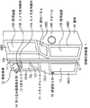
図1は、本発明を適用した画像印刷装置1の外観の構成例を示している。筐体10の正面中央の垂直な面10Aには、カメラ支持装置11A,11Bを介して撮影装置12が設けられている。CCD(Charge Coupled Device)カメラ13を内蔵している撮影装置12は、カメラ支持部材11Bを軸として、あらゆる角度にCCDカメラ13の撮影方向を変更することができ、利用者は、好みの角度に調整して、自らの写真(画像)を撮影することができる。撮影装置12は、取り込み画像表示部14を有し、CCDカメラ13が撮影している取り込み画像を、表示する。
【0012】
面10Aには、スライドレール14が設けられており、利用者は、操作パネル16に表示されている後述する操作ボタンを操作するなどして、スライドレール14の駆動可能範囲内で、撮影装置12を上下方向に移動させることができる。なお、カメラ支持部材11Aには、床からの高さを検出するセンサが、カメラ支持部材11Bには、所定方向を基準として、CCDカメラ13が撮影している撮影角度を検出するセンサが、それぞれ設けられている。カメラ支持部材11A,11Bのセンサにより検出された高さ、および撮影角度の情報は、撮影方向検出装置50(図3)に通知される。
【0013】
筐体10の正面に向かって、面10Aの左右、かつ、筐体10の上半分の、ほぼ垂直な面10LB,10RBにそれぞれ配置されている照明装置15L,15Rは、撮影の際のフラッシュとして機能するとともに、筐体10および利用者を囲むカーテン31(図2)、および背景パネル32(図2)により外光が遮断されているため、撮影前の状態においても利用者を照明する。
【0014】
筐体10の正面に向かって、面10Aの右側、かつ、筐体10のほぼ中央の、若干上方を向いている面10RCに配置されている操作パネル16は、液晶ディスプレイまたはCRT(Cathode−Ray Tude)より構成されるモニタと、その上部に積層されるタッチパネルから構成される。CCDカメラ13により撮影された画像が操作パネル16に表示されるため、利用者は、操作パネル16に直接触れることにより、撮影画像に後述する落書き処理を施すことができる。また、操作パネル16には、撮影画像の他に、画像プリントの作成、および印刷処理の進行段階に応じて種々の選択ボタン、メッセージなどが表示され、操作パネル16に表示された選択ボタンに直接触れて、選択することにより撮影手順が進行される。
【0015】
筐体10の正面に向かって、面10Aの左側、かつ、筐体10のほぼ中央の、若干上方を向いている面10LCには、基本的な撮影手順などが、文字を直接プリントするなどして表示されている。また、面10LCにも、面10RCに設けられているような操作パネルを設置することができ、これにより、複数の利用者が、編集情報などを、同時に入力しやすくすることができる。さらに、撮影進行に関する基本的な操作ボタン(例えば、撮影開始を指示するとき操作される撮影ボタン、または撮影装置12の高さを調整するとき操作される調整ボタンなど)を配置するようにしても良い。
【0016】
筐体10の正面に向かって、面10Aの左右、かつ、筐体10の下半分の、ほぼ垂直な面10LD,10RDに、それぞれ配置されている照明装置17L,17Rは、照明装置15L,15Rと同様の機能を有している。また、面10LDの左上には、硬貨投入口18が設けられており、利用者が所定の代金を投入すると、撮影手順が開始される。
【0017】
筐体10の左右の側面には、それぞれスピーカ19L(図2),19Rが設けられており、利用者に対して、硬貨を投入してからの撮影手順を案内する音声ガイダンスや、利用者が操作パネル16に表示されている自分自身の撮影画像に対して、編集入力する際の音声ガイダンスなどをステレオ方式で出力する。
【0018】
図2は、図1の画像印刷装置1を他の装置と組み合わせた状態を示しており、筐体10の上部に設けられている図示せぬカーテンフレームに、カーテン31が取り付けられている。カーテン31は、外光を遮断し、良好な画像を撮影することができるようにする。また、撮影している利用者の背景となる部分に、背景パネル32が取り付けられている。さらに、筐体10の左側面には、シール取出口30が設けられており、撮影し、画像編集した撮影画像が、所定数に分割されたシールに印刷されて排出される。
【0019】
図3は、画像印刷装置1の内部の電気的構成例を示すブロック図である。図1および図2と対応する部分については同一符号を付してある。
【0020】
CPU(Central Processing Unit)42は、ROM(Read Only Memory)43に記憶されているプログラムに従って、全体の動作、処理を制御する。そのため、各処理部は、バス41を介してCPU42に接続され、制御される。
【0021】
RAM(Random Access Memory)44は、CPU42が実行するプログラムの他、作業用データを記憶するとともに、各処理部において利用者が行った選択、指示などのデータを一時的に記憶する。
【0022】
ドライバ45は、図示せぬCD−ROM(Compact Disk−Read Only Memory)などの記録媒体を駆動し、記録情報を読み出す。CD−ROMなどの記録媒体には、撮影処理、落書き処理などを含む種々の処理を行うためのプログラムが記録されており、それらのプログラムは実行時に、RAM44に転送されて実行される。また、CD−ROMには、音声のガイダンスデータが記録されており、音声出力装置54は、CPU42の指示に基づいてCD−ROMに記録されている音声ガイダンスデータを読み出してスピーカ19L,19Rに出力する。スピーカ19L,19Rが利用者に対して出力するガイダンスには、操作方法や、撮影直前のカウントダウンなどが含まれる。
【0023】
また、ドライバ45が図示せぬCD−ROMから読み出す記録情報には、CCDカメラ13が撮影した被写体の画像データの前景として合成されるフレーム画像データ、および被写体の画像データの背景として合成される背景画像データが含まれる。
【0024】
硬貨処理部46は、硬貨投入口18から投入された硬貨の金額を検出し、所定の代金が投入されたと判定した場合、その旨をCPU42に通知する。
【0025】
プリンタ47は、画像シールを作成する部分であり、CCDカメラ13により撮影され、後述の落書き処理などが施された後の画像(プリントすべきものとして確定した画像であり、以下、これをプリント画像と称する)をシール紙などに印刷し、出力する。プリンタ47は、利用者が選択したプリント画像を、所定の分割単位で剥がせるようなシールシート上に印刷する。
【0026】
撮影装置12には、CCDカメラ13および取り込み画像表示部14の他に、ズーム駆動モータ48が内部に配置される。ズーム駆動モータ48は、例えば、利用者が操作パネル16に表示された不図示のズーム調整ボタンを操作することにより入力した信号を受信したCPU42からの指示に基づいて、ズーム機能を駆動する。
【0027】
撮影装置駆動モータ49も、ズーム駆動モータ48と同様に、例えば、利用者が操作パネル16に表示された不図示の高さ調整ボタンを操作することにより入力した信号を受信したCPU42からの指示に基づいて、撮影装置12の高さを調整する。
【0028】
撮影方向検出装置50は、カメラ支持部材11Aのセンサから常に通知される撮影装置12の床からの高さ、およびカメラ支持部材11Bのセンサから常に通知されるCCDカメラ13の撮影角度に基づいて、撮影装置12の撮影方向を検出し、合成画像生成装置51に対して常に通知する。
【0029】
合成画像生成装置51は、画像を合成するためのフレームバッファを有しており、CCDカメラ13が撮影した利用者の画像に、ドライバ45から提供されたフレーム画像および背景画像を合成し、合成した画像情報を、モニタ52にリアルタイムで表示させる。合成処理のためのフレームバッファは、被写体の画像用の領域と、背景画像用の領域と、フレーム画像用の領域とに分けられている。それぞれの画像データは、画素毎に数値化され、合成画像生成装置51は、それぞれの領域毎に設定された閾値に基づいて、画像合成処理を行う。また、ドライバ45から提供されるフレーム画像および背景画像は、3次元のCG(Compute Graphics)データであるため、合成画像生成装置51は、撮影方向検出装置50から常に通知される撮影装置12の撮影方向に応じて、フレーム画像および背景画像の表示角度を演算して、合成処理する。合成処理の詳細については、後述する。
【0030】
合成画像生成装置51は、利用者が操作パネル16に表示されている不図示の撮影ボタンを操作することにより行われた撮影のタイミングに併せて、その瞬間に合成処理した画像を内部の記憶部に記憶する。合成画像生成装置51は、複数枚の合成画像を記憶できるが、例えば、本実施の形態においては、利用者の回転率等を考慮して、最大4枚まで記憶することができる。
【0031】
また、合成画像生成装置51は、画像合成処理のためのフレームバッファの他に、編集処理のためのフレームバッファを有する。フレームバッファは、デュアルポートメモリにより構成され、それぞれの領域が一枚分の撮影画像を記憶できる2つの領域に分けて使用される。フレームバッファの第1の領域には、利用者が選択した編集処理の対象の合成画像が入力され、記憶される。
【0032】
一方、第2の領域は、落書き処理や明るさ調整などの編集処理において使用される記憶領域であり、利用者が編集対象の合成画像を選択した時点では、第1の領域と同一の合成画像が記憶される。すなわち、編集処理(落書き処理)において、利用者が操作パネル16から落書きを入力すると、その入力データがタッチパネル53を介して第2の領域内に書き込まれる。なお、利用者は、消しゴム処理を指定することにより、一度付加した落書きを消去し、元の画像に戻すことができる。その場合、合成画像生成装置51は、その消しゴムで指定された部分の画像データを第1の領域から読み出し、第2の領域に書き込ことにより、利用者が消しゴムで指定した部分を、落書き処理を行う前の合成画像にもどす。
【0033】
合成画像生成装置51は、CPU42からの指示に基づいて合成画像とともに、ドライバ45から供給される撮影手順の案内画面などをモニタ52に表示させる。また、合成画像生成装置51は、モニタ52の上に積層されている透明なタッチパネル53からの入力情報を検出し、CPU42に通知する。
【0034】
次に、図4および図5のフローチャートを参照して、画像印刷装置1の印刷処理について説明する。
【0035】
ステップS1において、CPU42は、硬貨処理部46からの通知に基づいて、代金が投入されたか否かを判定する。CPU42は、代金が投入されたと判定するまで、ドライバ45が図示せぬCD−ROMから読み出したデモ画面を操作パネル16に表示させる。すなわち、このとき、デモ画面の画像データが合成画像生成装置51に供給され、モニタ52に表示される。CPU42は、代金が投入されたと判定した場合、ステップS2の処理に進む。
【0036】
ステップS2において、CPU42は、CCDカメラ13が撮影している取り込み画像に、ドライバ45から提供された撮影案内画面を重畳した画像情報を合成画像生成装置51に供給し、モニタ52に表示することを指示する。撮影案内には、CCDカメラ13の撮影角度を調整できる旨の案内、不図示の高さ調整ボタンを操作して、撮影装置12の高さを調整できる旨の案内、CCDカメラ13のズーム機能を駆動させることができる旨の案内などが含まれる。また、CPU42は、撮影案内画面を表示させるとともに、音声出力装置54に対して、ドライバ45から提供された音声ガイダンスを出力させることもできる。さらに、CPU42は、CCDカメラ13が撮影している取り込み画像を取り込み画像表示部14に供給し、表示させる。
【0037】
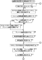
ステップS3において、CPU42は、フレーム画像選択画面をモニタ52に表示させる。フレーム画像選択画面には、ドライバ45がCD−ROMから読み込んだ複数のフレーム画像が表示され、利用者は、操作パネル16を直接触れることにより、所定のフレーム画像を選択する。また、利用者は、CCDカメラ13で撮影した画像をフレーム画像とすることができるため、フレーム画像選択画面には、フレーム画像を撮影するとき操作される不図示のフレーム画像撮影ボタンも表示される。
【0038】
ステップS4において、CPU42は、タッチパネル53からの通知に基づいて、フレーム画像撮影ボタンが操作されたか否かを判定する。CPU42は、フレーム画像撮影ボタンが操作されたと判定した場合、ステップS5の処理に進む。
【0039】
ステップS5において、CPU42は、カウントダウン画像を表示し、フレーム画像を撮影する。撮影までのカウントダウンの画像には、例えば、数字が所定の周期で、5,4,3,2,1と順次小さい値となる画像などが含まれており、CPU42は、カウントダウン画像に併せて、スピーカ19L,19Rから音声でカウントダウンを出力させる。
【0040】
また、ステップS5の処理でカウントダウンの処理が終了したとき、CPU42は、CCDカメラ13に対して、撮影することを指示する。それと同時に、照明装置15L,15Rおよび照明装置17L,17Rに対して、フラッシュの発生を指示する。
【0041】
ステップS5において、フレーム画像を撮影した後、またはステップS4において、CPU42によりフレーム画像撮影ボタンが操作されてないと判定された場合(フレーム画像選択画面に表示された中から、利用者がフレーム画像を選択した場合)、処理はステップS6に進む。
【0042】
ステップS6において、CPU42は、フレーム画像選択画面の中から選択されたフレーム画像、またはステップS5の処理で撮影したフレーム画像を設定する。すなわち、CPU42は、フレーム画像を合成画像生成装置51のフレーム画像用の領域に記憶させる。
【0043】
図6(A)は、CPU42がフレーム画像用の領域に設定したフレーム画像の例を示している。この例においては、右下にポストが配置されたフレーム画像とされている。
【0044】
図7(A)は、図6(A)に示すフレーム画像データを画素毎に数値化した例を模式的に示しており、各画素は、00乃至99のいずれかの値となる。図7(A)の例においては、ポストに対応する部分の画素のR,G,Bの値が(00,00,00)と、その他の部分の画素のR,G,B値が(99,99,99)と数値化されている。
【0045】
ステップS7において、CPU42は、背景画像選択画面をモニタ52に表示させる。背景画像選択画面には、フレーム画像選択画面と同様に、ドライバ45がCD−ROMから読み込んだ複数の背景画像が表示され、利用者は、操作パネル16を直接触れることにより、背景画像を選択する。
【0046】
ステップS8において、CPU42は、背景画像選択画面の中から選択された背景画像を設定する。すなわち、CPU42は、背景画像を合成画像生成装置51の背景画像用の領域に記憶させる。また、フレーム画像を利用者が撮影した画像とすることができるのと同様に、背景画像撮影処理を設けて、その処理により撮影された背景画像を利用するようにしても良い。
【0047】
図6(B)は、CPU42が合成画像生成装置51の背景画像用の領域に設定した背景画像の例を示している。この例においては、まっすぐのびる道路の先に山があり、空には雲が配置されている背景画像とされている。
【0048】
図7(B)は、図6(B)に示す背景画像データを画素毎に数値化した例を模式的に示している。図7(B)の例においては、全ての画素のR,G,Bの値が(70,70,70)と数値化されている。
【0049】
ステップS9において、撮影方向検出装置50は、CPU42からの指示に基づいて、利用者が調整したCCDカメラ13の撮影方向を検出する。すなわち、撮影方向検出装置50は、カメラ支持部材11Aに設置されているセンサから通知されたCCDカメラ13(カメラ支持部材11A)の床からの高さに関する情報、およびカメラ支持部材11Bに設置されているセンサから通知された所定角度を基準としたCCDカメラ13の撮影角度に関する情報に基づいて、CCDカメラ13の撮影方向を検出する。
【0050】
ステップS10において、合成画像生成装置51は、CPU42からの指示に基づいて、CCDカメラ13が撮影している取り込み画像に、フレーム画像および背景画像を合成する。すなわち、合成画像生成装置51は、ステップS9の処理で、撮影方向検出装置50が検出したCCDカメラ13の撮影方向に応じて、フレーム画像および背景画像の表示を変化させ、CCDカメラ13が撮影している取り込み画像(利用者の画像)と合成する。
【0051】
図6(C)は、CPU42が合成画像生成装置51の被写体用の領域に取り込んでいる被写体の画像の例を示している。この例においては、2人の利用者が、並んで直立している。
【0052】
図7(C)は、CCDカメラ13が取り込んでいる被写体の画像データを数値化した例を模式的に示している。利用者に対応する部分の画素のR,G,Bの値は、(50,50,50)と数値化されている。
【0053】
図7(D)は、合成画像生成装置51がフレーム画像(図7(A))、背景画像(図7(B))、並びに利用者の画像(図7(C))を合成した合成画像データを数値化した例を模式的に示している。
【0054】
合成画像生成装置51には、それぞれの領域毎に合成処理に用いる閾値が設定されている。すなわち、利用者の取り込み画像データ(図7(C))においては、R,G,Bの全ての値が閾値21以下の値をとる画素の部分には、背景画像(図7(B))が合成され、フレーム画像(図7(A))においては、R,G,Bの全ての値が閾値99の値をとる画素の部分には、背景画像(図7(B))および取り込み画像(図7(C))が合成される。
【0055】
ステップS11において、CPU42は、ステップS10の処理で合成画像生成装置51が生成した合成画像をモニタ52(操作パネル16)に表示させる。
【0056】
図8は、ステップS11の処理において、CPU42がモニタ52に表示させた合成画像の例を示している。なお、ステップS10の処理において、合成画像生成装置51は、図6(A)のフレーム画像、および図6(B)の背景画像に基づいて合成画像を生成するものとする。
【0057】
図8(A)は、CCDカメラ13(撮影装置12)の高さが高さh2(図1)付近の高さで、CCDカメラ13の撮影角度がほぼ水平の場合に、合成画像生成装置51が合成処理し、モニタ52に表示させる合成画像の例を示している。この例においては、合成画像生成装置51は、図6(A)に示すフレーム画像と、図6(B)に示す背景画像を、CCDカメラ13が撮影している図6(C)に示す利用者の取り込み画像に合成する。
【0058】
図8(B)は、CCDカメラ13(撮影装置12)の高さが高さh3(図1)付近の高さで、CCDカメラ13の撮影角度が水平を基準として、約60度上方を向いている場合に、合成画像生成装置51が合成処理し、モニタ52に表示させる合成画像の例を示している。この例においては、合成画像生成装置51は、図6(A)に示すフレーム画像を、約60度下方からの眺めとしたフレーム画像と、図6(B)に示す背景画像を、約60度下方からの眺めとした背景画像を、CCDカメラ13が約60度下方から撮影している利用者の取り込み画像に合成する。すなわち、フレーム画像のポストは、下面が少し表示されており、背景画像には、図8(A)の場合と較べて、雲が画像の中心方向に移動して表示されている。
【0059】
図8(C)は、CCDカメラ13(撮影装置12)の高さが高さh1(図1)付近の高さで、CCDカメラ13の撮影角度が水平を基準として、約60度下方を向いている場合に、合成画像生成装置51が合成処理し、モニタ52に表示させる合成画像の例を示している。この例においては、合成画像生成装置51は、図6(A)に示すフレーム画像を、約60度上方からの眺めとしたフレーム画像と、図6(B)に示す背景画像を、約60度上方からの眺めとした背景画像を、CCDカメラ13が約60度上方から撮影している利用者の取り込み画像に合成する。すなわち、フレーム画像のポストは、上面が少し表示されており、背景画像には、図8(A)の場合と較べて、道路が画像の中心方向に移動して表示されている。
【0060】
ステップS12において、CPU42は、CCDカメラ13の撮影方向を調整するために予め設定された所定時間が経過したか否か、または、ステップS11の処理で表示される合成画像とともに、操作パネル16に表示される不図示の撮影ボタンが操作されたか否かを判定する。撮影ボタンは、利用者が操作パネル16に表示されている合成画像を確認しながら、CCDカメラ13を好みの角度に調整した後、撮影処理を開始するとき操作される。CPU42は、所定時間が経過していない、かつ、撮影ボタンが操作されていないと判定した場合、ステップS9の処理に戻り、それ以降の処理を繰り返し実行する。
【0061】
ステップS12において、CPU42は、所定時間が経過した、または、撮影ボタンが操作されたと判定した場合、ステップS13の処理に進む。
【0062】
ステップS13において、CPU42は、操作パネル16にカウントダウン画像を表示させる。操作パネル16に表示されるカウントダウン画像は、ステップS5の処理で表示される画像と同様の画像である。
【0063】
ステップS13の処理でカウントダウンの処理が終了したとき、ステップS14において、CPU42は、CCDカメラ13に対して撮影することを指示する。それと同時に、照明装置15L,15Rおよび照明装置17L,17Rに対して、フラッシュの発生を指示する。このとき、CCDカメラ13が撮影した合成画像データは、合成画像生成装置51に記憶される。
【0064】
ステップS15において、CPU42は、操作パネル16にプリント画像選択画面を表示させる処理を実行する。すなわち、CPU42は、合成画像生成装置51に記憶されている撮影画像を読み出し、モニタ52に表示させる(既に、撮影画像が複数枚(最大4枚)記憶されている場合、それらの一覧を表示させる)。それに対して、利用者は、操作パネル16に直接触れることによりプリント画像を選択する。
【0065】
ステップS16において、CPU42は、タッチパネル53からの通知に基づいて、プリント画像が選択されたか否かを判定する。CPU42は、プリント画像が選択されていないと判定した場合、ステップS17の処理に進む。
【0066】
ステップS17において、CPU42は、合成画像生成装置51の記憶部を確認し、既に4回撮影済みである(4枚の撮影画像が記憶されている)か否かを判定する。CPU42において、まだ4回撮影していないと判定した場合、ステップS9の処理に戻り、撮影処理を繰り返す。また、ステップS17において、CPU42は、既に4回撮影済みであると判定した場合、ステップS16の処理に戻り、プリント画像が選択されるまで待機する。
【0067】
ステップS16において、CPU42は、プリント画像が選択されたと判定した場合、ステップS18の処理に進む。それとともに、CPU42は、選択されたプリント画像を合成画像生成装置51の編集処理用のフレームバッファの第1および第2の記憶領域に記憶させる。
【0068】
ステップS18において、CPU42は、モニタ52(操作パネル16)に、選択した画像に対して、利用者が落書き処理を行うか否かを選択するボタンを表示させる。そして、CPU42は、タッチパネル53からの通知に基づいて、落書き処理が選択されたか否か(そのボタンが操作されたか否か)を判定する。CPU42は、タッチパネル53からの通知に基づいて、落書き処理を実行することが選択されたと判定した場合、ステップS19の処理に進む。
【0069】
ステップS19において、CPU42は、落書き画面をモニタ52(操作パネル16)に表示させる。落書き画面には、利用者に対して、撮影画像に落書する色を選択するとき操作される「色選択ボタン」、落書きの線の太さを選択するとき操作される「太さ選択ボタン」、落書き処理を終了して、落書き編集されたプリント画像をプリントするとき操作される「プリントボタン」などが表示される(いずれも図示せず)。
【0070】
また、ステップS19において、CPU42は、落書き入力に基づいて画像編集処理を実行する。すなわち、CPU42は、合成画像生成装置51の編集処理用のフレームバッファの第2の領域に記憶されている画像に対して、画像データを上書きする。
【0071】
ステップS20において、CPU42は、落書き処理のために予め設定されている所定時間が経過したか否か、または、操作パネル16に表示されているプリントボタン(図示せず)が操作されたか否かを判定する。CPU42は、所定時間が経過しておらず、かつ、プリントボタンが操作されていないと判定した場合、ステップS19の処理に戻り、それ以降の処理を繰り返し実行する。
【0072】
ステップS20において、CPU42は、所定時間が経過したか、または、タッチパネル53からの通知に基づいて、プリントボタンが操作されたと判定した場合、ステップS21の処理に進む。また、ステップS18において、CPU42は、落書き処理が選択されていないと判定した場合、ステップS19,S20の処理をスキップし、ステップS21に進む。
【0073】
ステップS21において、CPU42は、シールシートのサイズを利用者に選択させる分割数選択画面を表示させる。利用者は、この画面から、操作パネル16に直接触れることで分割数を選択する。
【0074】
ステップ S 22において、CPU42は、プリンタ47に対して、利用者が選択した分割数のシールシートに、画像(合成画像生成装置51の編集処理用のフレームバッファの第2の領域に記憶されている画像)をプリントすることを指示する。この指示に基づいてプリンタ47によりプリントが行われ、シールシートがシール取出口30から排出される。その後、処理はステップS1に戻り、それ以降の処理が繰り返し実行される。
【0075】
以上においては、撮影装置12を上下方向に移動可能であるとしたが、例えば、図9に示すように、筐体10の面10Aに、固定された複数個のCCDカメラを設けるようにしてもよい。この場合、画像印刷装置1には、それぞれのCCDカメラの撮影角度に応じたフレーム画像および背景画像のみが用意される。
【0076】
図9の例においては、図1の位置h1に対応する高さに撮影装置12Aが、位置h2に対応する高さに撮影装置12Bが、位置h3に対応する高さに撮影装置12Cがそれぞれ設けられている。なお、撮影装置12Aは、CCDカメラ13Aおよび取り込み画像表示部14Aにより、撮影装置12Bは、CCDカメラ13Bおよび取り込み画像表示部14Bにより、撮影装置12Cは、CCDカメラ13Cおよび取り込み画像表示部14Cにより、それぞれ構成されている。
【0077】
CCDカメラ13Aは、水平方向を基準として約60度下方を、CCDカメラ13Bは、水平方向を、CCDカメラ13Cは、水平方向を基準として約60度上方を、それぞれ指向している。また、CCDカメラ13A,13B,13Cの撮影角度を変更できるようにしても良い。
【0078】
以上においては、利用者は、編集処理を入力する場合、操作パネル16を直接触れることとしたが、ペン型の入力装置を操作パネル16の近傍に配置して、それにより、入力するようにしても良い。
【0079】
また、図1において、撮影装置12は、上下方向にのみ、移動可能であるとしたが、スライドレール14と、様々な角度で交差するスライドレールを設けて、あらゆる角度から撮影可能としても良い。また、カメラ支持部材に、多くの関節部を設け、撮影装置12を移動させるようにしても良い。
【0080】
【発明の効果】
本発明の画像印刷装置および方法によれば、アミューズメント性が高い、より効果的なサービスを提供することができる。
【図面の簡単な説明】
【図1】本発明を適用した画像印刷装置の外観の構成例を示す斜視図である。
【図2】図1の画像印刷装置の他の装置と組み合わせた場合の構成例を示す斜視図である。
【図3】図1の画像印刷装置の内部の電気的構成例を示すブロック図である。
【図4】図1の画像印刷装置の処理を説明するフローチャートである。
【図5】図4に続くフローチャートである。
【図6】フレーム画像および背景画像の例を示す図である。
【図7】合成処理を説明する図である。
【図8】合成画像の例を示す図である。
【図9】本発明を適用した画像印刷装置のさらに他の外観の構成例を示す斜視図である。
【符号の説明】
1 画像印刷装置
10 筐体
11Aおよび11B カメラ支持部材
13 CCDカメラ
16 操作パネル
41 バス
42 CPU
43 ROM
44 RAM
45 ドライバ
47 プリンタ
49 撮影装置駆動モータ
50 撮影方向検出装置
51 合成画像生成装置
52 モニタ
53 タッチパネル[0001]
TECHNICAL FIELD OF THE INVENTION
The present invention relates to an image printing apparatus.And methodsIn particular, an image printing apparatus capable of providing a more effective service with high amusement propertiesAnd methodsAbout.
[0002]
[Prior art]
2. Description of the Related Art Recently, an image printing apparatus (for example, Print Club (trademark)) that captures an image of a user, combines the image with a background image prepared in advance, prints the image on a sticker sheet or the like, and outputs the image is popular. .
[0003]
For example, Japanese Patent Application Laid-Open No. H11-84522 proposes that in such an image printing apparatus, a camera is moved to capture an image and the image is synthesized with a background image. In this case, the user can shoot from various angles, and can create print images that give various impressions.
[0004]
[Problems to be solved by the invention]
However, in the image printing apparatus disclosed in the above-mentioned publication, when the background image is not stereoscopic image data, there is a problem that the boundary with the background image becomes unnatural and lacks interest.
[0005]
The present invention has been made in view of such a situation, and improves the amusement performance by changing the display direction of the background image and the frame image according to the shooting angle of the camera and combining the background image and the frame image with the image of the user. That can be done.
[0006]
[Means for Solving the Problems]
Of the present inventionFirstThe image printing deviceA first photographing control unit for controlling to repeatedly photograph a subject as a user using a photographing unit whose photographing direction can be changed, and a subject sequentially obtained by repeated photographing controlled by the first photographing control unit And a foreground image setting unit for setting a foreground image of the subject image, which is combined with each of the images of the subject, and a subject image sequentially obtained by repeated shooting under the control of the first shooting control unit. A background image setting means for setting a background image of a subject image;Shooting directionrepetitionDetecting means for detecting, in the shooting direction detected by the detecting meansIn response, the display of the foreground image set by the foreground image setting means and the display of the background image set by the background image setting means are changed in the same direction as the shooting direction, and further controlled by the first shooting control means. First synthesizing means for synthesizing a foreground image and a background image changed in the same direction as the shooting direction with each of the images of the subject sequentially obtained by shooting, and a result of the synthesis processing by the first synthesizing means. While checking the first synthesized image, the obtained first synthesized images are sequentially displayed on the display unit so that the shooting direction can be adjusted to a desired angle and then a shooting instruction can be input. Display control means, and first display control means for controlling the display control means to sequentially display the first synthesized images obtained by the synthesis processing by the first synthesis means on the display unit, and to control the operation by the subject. A second photographing unit for controlling the photographing unit to photograph the subject based on the photographing instruction received by the photographing instruction receiving unit, the photographing instruction receiving unit receiving a photographing instruction input through the input unit; The display of the foreground image set by the foreground image setting means and the background image set by the background image setting means are changed in the same direction as the shooting direction in accordance with the shooting direction detected by the control means and the detection means. Further, a second synthesizing unit for synthesizing a foreground image and a background image changed in the same direction as the shooting direction with an image of the subject obtained by the shooting controlled by the second shooting control unit, and a printing unit. Using the second composite image, which is the result of the composition by the second compositing means, as a seal sheet.PrintControlPrint control meansPrepareIt is characterized by the following.
[0007]
The first imaging control unit executes, for example, the process of step S2. CPU The foreground image setting means executes, for example, the process of step S6 CPU The background image setting means executes, for example, the process of step S8. CPU The detecting means is constituted by, for example, a photographing direction detecting device, the first synthesizing means is constituted by, for example, a synthesized image generating device which executes the processing of step S10, and the display controlling means is constituted by, for example, step Execute the process of S11 CPU The photographing instruction receiving means is constituted by, for example, an operation panel, and the second photographing control means executes, for example, the process of step S14. CPU The second synthesizing unit is configured by, for example, a synthesized image generating device that executes the process of step S14, and the printing unit is configured by, for example, a printer.Be composed.
[0008]
Of the present inventionFirstIn image printing devices,The image of the subject is controlled so that the user is repeatedly photographed of the subject using the photographing unit whose photographing direction can be changed, and is synthesized with each of the images of the subject obtained by the repeated photographing. The foreground image of the subject is set, the background image of the subject image is set to be combined with each of the subject images obtained by the repeated shooting, the shooting direction of the shooting unit is repeatedly detected, and the detected shooting direction is set. The display of the foreground image and the background image is changed so as to be in the same direction as the shooting direction, and further, for each of the images of the subject sequentially obtained by shooting, the foreground image changed in the same direction as the shooting direction And the background image is synthesized, and the subject adjusts the shooting direction to a desired angle while checking the first synthesized image as a result of the synthesis processing, and then inputs a shooting instruction. The obtained first synthesized images are sequentially displayed on the display unit so that the photographing instruction input by the subject through the operation input unit is received, and based on the received photographing instruction. In accordance with the detected shooting direction, the display of the foreground image and the background image is changed so as to be in the same direction as the shooting direction. The foreground image and the background image changed in the same direction are combined, and the second combined image, which is the result of the combination, is printed on the seal sheet using the printing unit.PrintedIs controlled as.
[0009]
Of the present inventionFirstAccording to the image printing device,Using a photographing unit whose photographing direction can be changed, control is performed so as to repeatedly photograph the subject as a user, and a foreground image of the subject image is combined with each of the subject images sequentially obtained by the repeated photographing. Then, a background image of the image of the subject, which is combined with each of the images of the subject sequentially obtained by repeated shooting, is set.Shooting directionrepetitionDetect, and in the detected shooting directionAccordingly, the display of the foreground image and the background image is changed in the same direction as the shooting direction, and the foreground image and the background image changed in the same direction as the shooting direction are combined with each of the images of the subject sequentially obtained by shooting. Then, the first synthesized image obtained so that the subject can input a shooting instruction after adjusting the shooting direction to a desired angle while checking the first synthesized image that is the result of the synthesis processing. Are sequentially displayed on the display unit, and together with the shooting instruction input by the subject through the operation input unit, the control unit controls the imaging unit to shoot the subject based on the shooting instruction, and the detection is performed. The display of the foreground image and the background image is changed in the same direction as the shooting direction in accordance with the shooting direction, and the image of the subject obtained by shooting is further changed in the same direction as the shooting direction. Fine background image synthesized by using the printing unit, the second synthetic image is the result of combining the seal seatPrintControlAs a result, it is possible to provide a more effective service with high amusement properties.
[0010]
A storage unit that has two regions, a first region and a second region, and stores, in each region, composite image data corresponding to the composite image displayed by the display unit; An editing input receiving unit that receives the editing input; and an editing unit that edits the composite image data stored in the storage unit based on the editing input received by the editing input receiving unit. When the graffiti input is accepted by the means as the edit input, the composite image data stored in the second area of the storage means is edited based on the graffiti input, and the edited result is written in the second area, and the edit input is performed. When the receiving means receives an eraser input as an edit input, the eraser input of the composite image data stored in the first area of the storage means is performed. By reading out the portion designated by (1) and writing the combined image data stored in the second area of the storage means, the portion of the composite image designated by the eraser input is converted into the composite image before performing the graffiti processing. Can be returned.
A first image printing method according to the present invention includes a first photographing control step of controlling to repeatedly photograph a subject as a user by using a photographing unit whose photographing direction can be changed, and a first photographing control step. A foreground image setting step of setting a foreground image of the subject image, which is combined with each of the subject images sequentially obtained by the repeated shooting under the control of the processing, and a process controlled and repeated by the first shooting control step A background image setting step of setting a background image of the subject image, which is combined with each of the subject images sequentially obtained by the photographing, a detection step of repeatedly detecting a shooting direction of the shooting unit, and a detection step. The foreground image set by the processing of the foreground image setting step and the background image setting step The display of the background image set by the image processing is changed in the same direction as the photographing direction. Further, each of the images of the subject sequentially obtained by the photographing controlled by the processing of the first photographing control step is provided in the same direction as the photographing direction. A first synthesizing step of synthesizing the foreground image and the background image that have been changed into the first image and the photographing direction while confirming the first synthesized image that is the result of the synthesizing processing by the processing of the first synthesizing step And a display control step of controlling the display so that the obtained first combined images are sequentially displayed on the display unit so that the input can be performed after the angle is adjusted to a desired angle. The first synthesized image obtained by the synthesizing process in the first synthesizing step is sequentially displayed on the display unit, and the photographing instruction input by the subject through the operation input unit. A second photographing operation for controlling the photographing unit to photograph the subject based on the photographing instruction controlled and received by the processing of the photographing instruction reception control step for controlling the photographing instruction to be received; The control step and the display of the foreground image set by the processing of the foreground image setting step and the background image set by the processing of the background image setting step are performed in accordance with the shooting direction detected by the processing of the detection step. In the same direction as the shooting direction, and further combining the foreground image and the background image changed in the same direction as the shooting direction with the image of the subject obtained by the shooting controlled by the process of the second shooting control step. A synthesis step ofUsing the printing unit,A printing control step of controlling printing of a second synthesized image, which is a result of the synthesis by the processing of the second synthesis step, on a seal sheet.
A second image printing apparatus according to the present invention includes:Shooting directions are different from each otherFirst photographing control means for controlling to repeatedly photograph an object which is a user using any one of the plurality of photographing units, and sequential photographing controlled by the first photographing control means and repeatedly performed. Foreground image setting means for setting a foreground image of the subject image, which is combined with each of the subject images to be obtained, and combining with each of the subject images sequentially obtained by repeated shooting controlled by the first shooting control means. A background image setting means for setting a background image of the image of the subject, a specifying means for repeatedly specifying a shooting direction by specifying a shooting unit which has shot the subject, and a shooting direction specified by the specifying means. Changing the display of the foreground image set by the foreground image setting means, and the background image set by the background image setting means in the same direction as the shooting direction, A first synthesizing unit for synthesizing a foreground image and a background image changed in the same direction as the shooting direction with each of the subject images sequentially obtained by the shooting controlled by the first shooting control unit; Confirms a first synthesized image which is a result of the synthesizing process by the first synthesizing means. A display control unit that controls the display unit to sequentially display the obtained first combined images so that a photographing unit that photographs the subject is selected and a photographing instruction can be input while the photographing unit is being photographed. The first combined image controlled by the first combining unit is sequentially displayed on the display unit, and the imaging instruction receiving unit receives the imaging instruction input by the subject via the operation input unit. A second photographing control unit that controls the photographing unit to photograph the subject based on the photographing instruction received by the photographing instruction receiving unit, and a photographing direction specified by the specifying unit. The display of the foreground image set by the foreground image setting means and the display of the background image set by the background image setting means are changed in the same direction as the shooting direction. The image of the subject obtained by the photographing to be controlled by control means, a second combining means for combining the foreground image and the background image is changed to a photographing direction in the same direction,Using the printing unit,Printing a second synthesized image as a result of the synthesis by the second synthesizing means on the seal sheetControlA print control unit.
A second image printing method according to the present invention includes:Shooting directions are different from each otherA first photographing control step of controlling to repeatedly photograph a subject as a user using any one of the plurality of photographing units, and the photographing controlled and repeated by the processing of the first photographing control step A foreground image setting step of setting a foreground image of the image of the subject, which is combined with each of the images of the subject sequentially obtained by A background image setting step of setting a background image of an image of a subject, a specifying step of repeatedly specifying a shooting direction by specifying a shooting unit that has captured the subject, and a processing of the specifying step. Foreground image and background image settings set by the foreground image setting step according to the specified shooting direction The display of the background image set by the processing of the step is changed in the same direction as the photographing direction, and the image of the subject sequentially obtained by the photographing controlled by the processing of the first photographing control step is provided with the photographing direction and A first synthesizing step of synthesizing the foreground image and the background image changed in the same direction, and photographing the subject while confirming the first synthesized image which is a result of the synthesizing process by the processing of the first synthesizing step. And a display control step of controlling the display unit to sequentially display the obtained first combined images on the display unit so that a photographing unit to be selected and a photographing instruction can be input. The first synthesized image obtained by the synthesizing process by the first synthesizing means is sequentially displayed on the display unit, and is input via the operation input unit by the subject. A second photographing control step of controlling the photographing unit selected by the subject to photograph the subject based on the photographing instruction received in the process of the photographing instruction receiving step for receiving the shadow instruction; The display of the foreground image set by the processing of the foreground image setting step and the display of the background image set by the processing of the background image setting step are the same as the shooting direction according to the shooting direction specified by the processing of the specifying step. Direction, and further combines the foreground image and the background image, which are changed in the same direction as the shooting direction, with the image of the subject obtained by the shooting controlled by the process of the second shooting control step. Steps andUsing the printing unit,A printing control step of controlling printing of a second synthesized image, which is a result of the synthesis by the processing of the second synthesis step, on a seal sheet.
[0011]
BEST MODE FOR CARRYING OUT THE INVENTION
FIG. 1 shows an example of an external configuration of an
[0012]
A
[0013]
The
[0014]
The
[0015]
Basic photographing procedures, such as direct printing of characters, are performed on the surface 10LC, which faces the front of the
[0016]
The
[0017]
[0018]
FIG. 2 shows a state in which the
[0019]
FIG. 3 is a block diagram illustrating an example of an electrical configuration inside the
[0020]
A CPU (Central Processing Unit) 42 controls the overall operation and processing according to a program stored in a ROM (Read Only Memory) 43. Therefore, each processing unit is connected to the
[0021]
A RAM (Random Access Memory) 44 stores not only programs executed by the
[0022]
The driver 45 drives a recording medium such as a CD-ROM (Compact Disk-Read Only Memory) (not shown) and reads recorded information. On a recording medium such as a CD-ROM, programs for performing various processes including a photographing process, a graffiti process, and the like are recorded, and the programs are transferred to the
[0023]
The recording information read from a CD-ROM (not shown) by the driver 45 includes frame image data to be synthesized as the foreground of the image data of the subject captured by the
[0024]
The coin processing unit 46 detects the amount of coins inserted from the
[0025]
The printer 47 is a part for creating an image sticker, and is an image that has been photographed by the
[0026]
The photographing device 12 includes a
[0027]
Similarly to the
[0028]
The photographing direction detecting device 50 is based on the height from the floor of the photographing device 12 always notified from the sensor of the camera support member 11A and the photographing angle of the
[0029]
The synthesized
[0030]
The combined
[0031]
Further, the composite
[0032]
On the other hand, the second area is a storage area used in editing processing such as graffiti processing and brightness adjustment, and when the user selects a composite image to be edited, the same composite image as the first area is used. Is stored. That is, in the editing processing (graffiti processing), when the user inputs graffiti from the
[0033]
The composite
[0034]
Next, the printing process of the
[0035]
In step S <b> 1, the
[0036]
In step S2, the
[0037]
In step S3, the
[0038]
In step S4, the
[0039]
In step S5, the
[0040]
Further, when the countdown process is completed in the process of step S5, the
[0041]
After photographing the frame image in step S5, or when it is determined in step S4 that the frame image photographing button has not been operated by the CPU 42 (from among the displayed frame image selection screens, the user If it is selected, the process proceeds to step S6.
[0042]
In step S6, the
[0043]
FIG. 6A shows an example of a frame image set by the
[0044]
FIG. 7A schematically shows an example in which the frame image data shown in FIG. 6A is digitized for each pixel, and each pixel takes a value from 00 to 99. In the example of FIG. 7A, the R, G, and B values of the pixel corresponding to the post are (00, 00, 00), and the R, G, and B values of the other pixels are (99). , 99, 99).
[0045]
In step S7, the
[0046]
In step S8, the
[0047]
FIG. 6B shows an example of a background image set by the
[0048]
FIG. 7B schematically shows an example in which the background image data shown in FIG. 6B is digitized for each pixel. In the example of FIG. 7B, the values of R, G, and B of all pixels are quantified as (70, 70, 70).
[0049]
In step S9, the photographing direction detecting device 50 detects the photographing direction of the
[0050]
In step S10, the composite
[0051]
FIG. 6C shows an example of an image of a subject captured by the
[0052]
FIG. 7C schematically shows an example in which image data of a subject captured by the
[0053]
FIG. 7D shows a synthesized image obtained by synthesizing the frame image (FIG. 7A), the background image (FIG. 7B), and the user image (FIG. 7C) by the synthesized
[0054]
In the synthesized
[0055]
In step S11, the
[0056]
FIG. 8 shows an example of a composite image displayed on the monitor 52 by the
[0057]
FIG. 8A shows a case where the height of the CCD camera 13 (the photographing device 12) is near the height h2 (FIG. 1) and the photographing angle of the
[0058]
FIG. 8B shows a state in which the height of the CCD camera 13 (the photographing device 12) is near the height h3 (FIG. 1), and the photographing angle of the
[0059]
FIG. 8C shows a state in which the height of the CCD camera 13 (the photographing device 12) is near the height h1 (FIG. 1), and the photographing angle of the
[0060]
In step S12, the
[0061]
In step S12, if the
[0062]
In step S13, the
[0063]
When the countdown process is completed in the process of step S13, the
[0064]
In step S15, the
[0065]
In step S16, the
[0066]
In step S17, the
[0067]
If the
[0068]
In step S18, the
[0069]
In step S19, the
[0070]
In step S19, the
[0071]
In step S20, the
[0072]
In step S20, if the
[0073]
In step S21, the
[0074]
Steps
[0075]
In the above description, the photographing device 12 is movable in the vertical direction. For example, as shown in FIG. 9, a plurality of fixed CCD cameras may be provided on the
[0076]
In the example of FIG. 9, the imaging device 12A is provided at the height corresponding to the position h1 in FIG. 1, the
[0077]
The CCD camera 13A is directed downward by about 60 degrees with respect to the horizontal direction, the
[0078]
In the above description, when inputting the editing process, the user directly touches the
[0079]
In FIG. 1, the photographing device 12 is movable only in the vertical direction. However, a slide rail that intersects the
[0080]
【The invention's effect】
The image printing apparatus and method of the present inventionAccording to amusementIt is possible to provide highly effective and more effective services.
[Brief description of the drawings]
FIG. 1 is a perspective view illustrating a configuration example of an external appearance of an image printing apparatus to which the present invention has been applied.
FIG. 2 is a perspective view showing a configuration example when the image printing apparatus of FIG. 1 is combined with another apparatus.
FIG. 3 is a block diagram illustrating an example of an electrical configuration inside the image printing apparatus of FIG. 1;
FIG. 4 is a flowchart illustrating processing of the image printing apparatus of FIG. 1;
FIG. 5 is a flowchart following FIG. 4;
FIG. 6 is a diagram illustrating an example of a frame image and a background image.
FIG. 7 is a diagram illustrating a combining process.
FIG. 8 is a diagram illustrating an example of a composite image.
FIG. 9 is a perspective view illustrating a configuration example of still another external appearance of an image printing apparatus to which the present invention has been applied.
[Explanation of symbols]
1 Image printing device
10 Case
11A and 11B camera support members
13 CCD camera
16 Operation panel
41 bus
42 CPU
43 ROM
44 RAM
45 Driver
47 Printer
49 Camera drive motor
50 Photographing direction detection device
51 Synthetic image generation device
52 monitor
53 touch panel
Claims (5)
撮影方向が変更可能な前記撮影部を用いて前記ユーザである被写体の撮影を繰り返し行うように制御する第1の撮影制御手段と、
前記第1の撮影制御手段により制御されて繰り返される前記撮影により順次得られる被写体の画像のそれぞれに合成される、前記被写体の画像の前景画像を設定する前景画像設定手段と、
前記第1の撮影制御手段により制御されて繰り返される前記撮影により順次得られる被写体の画像のそれぞれに合成される、前記被写体の画像の背景画像を設定する背景画像設定手段と、
前記撮影部の撮影方向を繰り返し検出する検出手段と、
前記検出手段により検出された前記撮影方向に応じて、前記前景画像設定手段により設定された前記前景画像、および、前記背景画像設定手段により設定された前記背景画像の表示を前記撮影方向と同方向に変化させ、さらに、前記第1の撮影制御手段により制御される撮影により順次得られる被写体の画像のそれぞれに、前記撮影方向と同方向に変化させた前記前景画像および前記背景画像を合成する第1の合成手段と、
前記被写体が、前記第1の合成手段による合成処理の結果である第1の合成画像を確認しながら、前記撮影方向を所望の角度に調整してから撮影指示を入力することができるように、得られた前記第1の合成画像を順次前記表示部に表示するように制御する表示制御手段と、
前記表示制御手段により制御されて、前記第1の合成手段による合成処理により得られる前記第1の合成画像が順次前記表示部に表示されるとともに、前記被写体による前記操作入力部を介して入力された前記撮影指示を受け付ける撮影指示受付手段と、
前記撮影指示受付手段により受け付けられた前記撮影指示に基づいて、前記撮影部を制御して前記被写体を撮影させるように制御する第2の撮影制御手段と、
前記検出手段により検出された前記撮影方向に応じて、前記前景画像設定手段により設定された前記前景画像、および、前記背景画像設定手段により設定された前記背景画像の表示を前記撮影方向と同方向に変化させ、さらに、前記第2の撮影制御手段により制御される撮影により得られた前記被写体の画像に、前記撮影方向と同方向に変化させた前記前景画像および前記背景画像を合成する第2の合成手段と、
前記印刷部を用いて、前記第2の合成手段による合成の結果である第2の合成画像を前記シールシートに印刷するように制御する印刷制御手段と
を備えることを特徴とする画像印刷装置。 The housing has a photographing unit, a display unit, an operation input unit, and a printing unit, and allows the user to perform photographing and editing of the photographed image, and provides the user with a seal sheet on which the edited image is printed. In the image printing device to be provided,
First photographing control means for controlling to repeatedly photograph a subject as the user by using the photographing unit whose photographing direction can be changed,
Foreground image setting means for setting a foreground image of the image of the subject, which is combined with each of the images of the subject sequentially obtained by the imaging controlled and repeated by the first imaging control means;
Background image setting means for setting a background image of the image of the subject, which is combined with each of the images of the subject sequentially obtained by the photographing controlled and repeated by the first photographing control means;
Detecting means for repeatedly detecting a shooting direction of the shooting unit;
The display of the foreground image set by the foreground image setting means and the background image set by the background image setting means in the same direction as the shooting direction in accordance with the shooting direction detected by the detection means And further combining the foreground image and the background image changed in the same direction as the shooting direction with each of the subject images sequentially obtained by the shooting controlled by the first shooting control unit. 1;
In order that the subject can adjust the shooting direction to a desired angle and then input a shooting instruction while checking the first synthesized image that is the result of the synthesis processing by the first synthesis unit. Display control means for controlling to sequentially display the obtained first combined images on the display unit;
The first combined image obtained by the combining process by the first combining unit is controlled by the display control unit, is sequentially displayed on the display unit, and is input by the subject via the operation input unit. Shooting instruction receiving means for receiving the shooting instruction,
A second photographing control unit that controls the photographing unit to photograph the subject based on the photographing instruction received by the photographing instruction receiving unit;
The display of the foreground image set by the foreground image setting means and the background image set by the background image setting means in the same direction as the shooting direction in accordance with the shooting direction detected by the detection means And synthesizing the foreground image and the background image, which are changed in the same direction as the shooting direction, with the image of the subject obtained by shooting controlled by the second shooting control means. A synthesis means of
Using the printing unit, characterized in that the second composite image is a result of synthesis by the second combining means comprises a <br/> and print control means for printing on said sealing sheet Image printing device.
前記表示手段により表示された前記合成画像に対する編集入力を受け付ける編集入力受付手段と、Edit input receiving means for receiving an edit input for the composite image displayed by the display means,
前記編集入力受付手段により受け付けられた前記編集入力に基づいて前記記憶手段により記憶されている前記合成画像データを編集する編集手段とEditing means for editing the composite image data stored by the storage means based on the editing input received by the editing input receiving means;
をさらに備え、Further comprising
前記編集手段は、前記編集入力受付手段により、前記編集入力として落書き入力が受け付けられると、前記落書き入力に基づいて、前記記憶手段の前記第2の領域に記憶されている前記合成画像データを編集し、編集結果を前記第2の領域に書き込み、前記編集入力受付手段により、前記編集入力として消しゴム入力が受け付けられると、前記記憶手段の前記第1の領域に記憶されている前記合成画像データの、前記消しゴム入力により指定された部分を読み出し、前記記憶手段の前記第2の領域に記憶されている前記合成画像データに書き込むことにより、前記合成画像の、前記消しゴム入力により指定された部分を、落書き処理を行う前の合成画像に戻すWhen the editing input receiving unit receives a graffiti input as the editing input, the editing unit edits the composite image data stored in the second area of the storage unit based on the graffiti input. Then, an editing result is written in the second area, and when an eraser input is received as the editing input by the editing input receiving means, the edited image data of the synthesized image data stored in the first area of the storage means is read. By reading the portion designated by the eraser input and writing the combined image data stored in the second area of the storage means, the portion of the composite image designated by the eraser input is Return to composite image before performing graffiti processing
ことを特徴とする請求項1に記載の画像印刷装置。The image printing apparatus according to claim 1, wherein:
撮影方向が変更可能な前記撮影部を用いて前記ユーザである被写体の撮影を繰り返し行うように制御する第1の撮影制御ステップと、
前記第1の撮影制御ステップの処理により制御されて繰り返される前記撮影により順次得られる被写体の画像のそれぞれに合成される、前記被写体の画像の前景画像を設定する前景画像設定ステップと、
前記第1の撮影制御ステップの処理により制御されて繰り返される前記撮影により順次得られる被写体の画像のそれぞれに合成される、前記被写体の画像の背景画像を設定する背景画像設定ステップと、
前記撮影部の撮影方向を繰り返し検出する検出ステップと、
前記検出ステップの処理により検出された前記撮影方向に応じて、前記前景画像設定ステップの処理により設定された前記前景画像、および、前記背景画像設定ステップの処理により設定された前記背景画像の表示を前記撮影方向と同方向に変化させ、さらに、前記第1の撮影制御ステップの処理により制御される撮影により順次得られる被写体の画像のそれぞれに、前記撮影方向と同方向に変化させた前記前景画像および前記背景画像を合成する第1の合成ステップと、
前記被写体が、前記第1の合成ステップの処理による合成処理の結果である第1の合成画像を確認しながら、前記撮影方向を所望の角度に調整してから入力することができるように、得られた前記第1の合成画像を順次表示部に表示するように制御する表示制御ステップと、
前記表示制御ステップの処理により制御されて、前記第1の合成ステップによる合成処理により得られる前記第1の合成画像が順次前記表示部に表示されるとともに、前記被写体による前記操作入力部を介して入力された撮影指示を受け付けるように制御する撮影指示受付制御ステップと、
前記撮影指示受付制御ステップの処理により制御されて受け付けられた前記撮影指示に基づいて、前記撮影部を制御して前記被写体を撮影させるように制御する第2の撮影制御ステップと、
前記検出ステップの処理により検出された前記撮影方向に応じて、前記前景画像設定ステップの処理により設定された前記前景画像、および、前記背景画像設定ステップの処理により設定された前記背景画像の表示を前記撮影方向と同方向に変化させ、さらに、前記第2の撮影制御ステップの処理により制御される撮影により得られた前記被写体の画像に、前記撮影方向と同方向に変化させた前記前景画像および前記背景画像を合成する第2の合成ステップと、
前記印刷部を用いて、前記第2の合成ステップの処理による合成の結果である第2の合成画像を前記シールシートに印刷するように制御する印刷制御ステップと
を含むことを特徴とする画像印刷方法。 The housing has a photographing unit, a display unit, an operation input unit, and a printing unit, and allows the user to perform photographing and editing of the photographed image, and provides the user with a seal sheet on which the edited image is printed. An image printing method of an image printing apparatus to provide,
A first photographing control step of controlling to repeatedly photograph a subject as the user using the photographing unit whose photographing direction can be changed,
A foreground image setting step of setting a foreground image of the image of the subject, which is combined with each of the images of the subject sequentially obtained by the shooting controlled and repeated by the process of the first shooting control step;
A background image setting step of setting a background image of the subject image, which is combined with each of the subject images sequentially obtained by the photographing controlled and repeated by the processing of the first shooting control step;
A detection step of repeatedly detecting a shooting direction of the shooting unit ,
The foreground image set by the processing of the foreground image setting step, and the display of the background image set by the processing of the background image setting step, according to the shooting direction detected by the processing of the detection step. The foreground image, which is changed in the same direction as the shooting direction, is changed in the same direction as the shooting direction, and further, images of the subject sequentially obtained by shooting controlled by the process of the first shooting control step are respectively changed. And a first combining step of combining the background image;
The object is adjusted so that the photographing direction can be adjusted to a desired angle and then input while confirming a first synthesized image that is a result of the synthesis processing by the processing of the first synthesis step. A display control step of controlling to sequentially display the obtained first combined images on a display unit;
Controlled by the processing of the display control step, the first synthesized image obtained by the synthesis processing in the first synthesis step is sequentially displayed on the display unit, and the operation is performed by the subject via the operation input unit. A shooting instruction reception control step of controlling to receive the input shooting instruction,
A second photographing control step of controlling the photographing unit to photograph the subject based on the photographing instruction controlled and received by the processing of the photographing instruction reception control step;
The foreground image set by the processing of the foreground image setting step, and the display of the background image set by the processing of the background image setting step, according to the shooting direction detected by the processing of the detection step. The imaging direction is changed in the same direction, and further, the image of the subject obtained by the imaging controlled by the process of the second imaging control step, the foreground image changed in the same direction as the imaging direction, A second combining step of combining the background image;
A printing control step of controlling the printing unit to print a second synthesized image, which is a result of the synthesis by the processing of the second synthesis step, on the seal sheet. Image printing method.
撮影方向が互いに異なる複数の前記撮影部の内のいずれか1つを用いて前記ユーザである被写体を繰り返し撮影するように制御する第1の撮影制御手段と、First photographing control means for controlling to repeatedly photograph the subject as the user by using any one of the plurality of photographing units having different photographing directions,
前記第1の撮影制御手段により制御されて繰り返される前記撮影により順次得られる被写体の画像のそれぞれに合成される、前記被写体の画像の前景画像を設定する前景画像設定手段と、Foreground image setting means for setting a foreground image of the image of the subject, which is combined with each of the images of the subject sequentially obtained by the imaging controlled and repeated by the first imaging control means;
前記第1の撮影制御手段により制御されて繰り返される前記撮影により順次得られる被写体の画像のそれぞれに合成される、前記被写体の画像の背景画像を設定する背景画像設定手段と、Background image setting means for setting a background image of the image of the subject, which is combined with each of the images of the subject sequentially obtained by the photographing controlled and repeated by the first photographing control means;
前記被写体を撮影した前記撮影部を特定することで撮影方向を繰り返し特定する特定手段と、Specifying means for repeatedly specifying a shooting direction by specifying the shooting unit that has shot the subject;
前記特定手段により特定された前記撮影方向に応じて、前記前景画像設定手段により設定された前記前景画像、および、前記背景画像設定手段により設定された前記背景画像の表示を前記撮影方向と同方向に変化させ、さらに、前記第1の撮影制御手段により制御される撮影により順次得られる被写体の画像のそれぞれに、前記撮影方向と同方向に変化させた前記前景画像および前記背景画像を合成する第1の合成手段と、The foreground image set by the foreground image setting means, and the display of the background image set by the background image setting means in the same direction as the shooting direction according to the shooting direction specified by the specifying means. And combining the foreground image and the background image, which are changed in the same direction as the shooting direction, with each of the subject images sequentially obtained by the shooting controlled by the first shooting control unit. 1;
前記被写体が、前記第1の合成手段による合成処理の結果である第1の合成画像を確認しながら前記被写体を撮影する前記撮影部を選択し、撮影指示を入力することができるように、得られた前記第1の合成画像を順次表示部に表示するように制御する表示制御手段と、The subject can select the photographing unit that photographs the subject while confirming a first combined image that is a result of the combining processing by the first combining unit, and can input a photographing instruction. Display control means for controlling the displayed first combined image to be sequentially displayed on a display unit;
前記表示制御手段により制御されて、前記第1の合成手段による合成処理により得られる前記第1の合成画像が順次前記表示部に表示されるとともに、前記被写体による前記操作入力部を介して入力された撮影指示を受け付ける撮影指示受付手段と、The first combined image obtained by the combining process by the first combining unit is controlled by the display control unit, is sequentially displayed on the display unit, and is input by the subject via the operation input unit. Shooting instruction receiving means for receiving a shooting instruction,
前記撮影指示受付手段により受け付けられた前記撮影指示に基づいて、前記被写体が選択した撮影部を制御して前記被写体を撮影させるように制御する第2の撮影制御手段と、A second photographing control unit that controls the photographing unit selected by the subject to photograph the subject based on the photographing instruction received by the photographing instruction receiving unit;
前記特定手段により特定された前記撮影方向に応じて、前記前景画像設定手段により設定された前記前景画像、および、前記背景画像設定手段により設定された前記背景画像の表示を前記撮影方向と同方向に変化させ、さらに、前記第2の撮影制御手段により制御される撮影により得られた前記被写体の画像に、前記撮影方向と同方向に変化させた前記前景画像および前記背景画像を合成する第2の合成手段と、The display of the foreground image set by the foreground image setting means and the background image set by the background image setting means in the same direction as the shooting direction according to the shooting direction specified by the specifying means. And synthesizing the foreground image and the background image, which are changed in the same direction as the shooting direction, with the image of the subject obtained by shooting controlled by the second shooting control means. A synthesis means of
前記印刷部を用いて、前記第2の合成手段による合成の結果である第2の合成画像を前記シールシートに印刷するように制御する印刷制御手段とA printing control unit that controls the printing unit to print a second synthesized image that is a result of the synthesis by the second synthesis unit on the seal sheet;
を備えることを特徴とする画像印刷装置。An image printing apparatus comprising:
撮影方向が互いに異なる複数の前記撮影部の内のいずれか1つを用いて前記ユーザである被写体を繰り返し撮影するように制御する第1の撮影制御ステップと、A first photographing control step of controlling to repeatedly photograph the subject as the user using any one of the plurality of photographing units having different photographing directions;
前記第1の撮影制御ステップの処理により制御されて繰り返される前記撮影により順次得られる被写体の画像のそれぞれに合成される、前記被写体の画像の前景画像を設定する前景画像設定ステップと、A foreground image setting step of setting a foreground image of the image of the subject, which is combined with each of the images of the subject sequentially obtained by the shooting controlled and repeated by the process of the first shooting control step;
前記第1の撮影制御ステップの処理により制御されて繰り返される前記撮影により順次得られる被写体の画像のそれぞれに合成される、前記被写体の画像の背景画像を設定する背景画像設定ステップと、A background image setting step of setting a background image of the subject image, which is combined with each of the subject images sequentially obtained by the photographing controlled and repeated by the processing of the first shooting control step;
前記被写体を撮影した前記撮影部を特定することで撮影方向を繰り返し特定する特定ステップと、A specifying step of repeatedly specifying a shooting direction by specifying the shooting unit that has shot the subject;
前記特定ステップの処理により特定された前記撮影方向に応じて、前記前景画像設定ステップの処理により設定された前記前景画像、および、前記背景画像設定ステップの処理により設定された前記背景画像の表示を前記撮影方向と同方向に変化させ、さらに、前記第1の撮影制御ステップの処理により制御される撮影により順次得られる被写体の画像のそれぞれに、前記撮影方向と同方向に変化させた前記前景画像および前記背景画像を合成する第1の合成ステップと、The foreground image set by the processing of the foreground image setting step, and the display of the background image set by the processing of the background image setting step, according to the shooting direction specified by the processing of the specifying step. The foreground image changed in the same direction as the shooting direction, and further changed in the same direction as the shooting direction in each of the images of the subject sequentially obtained by the shooting controlled by the process of the first shooting control step. And a first combining step of combining the background image;
前記被写体が、前記第1の合成ステップの処理による合成処理の結果である第1の合成画像を確認しながら前記被写体を撮影する前記撮影部を選択し、撮影指示を入力することができるように、得られた前記第1の合成画像を順次表示部に表示するように制御する表示制御ステップと、The subject can select the photographing unit for photographing the subject while confirming a first combined image that is a result of the combining processing by the processing of the first combining step, and can input a photographing instruction. A display control step of controlling the obtained first combined image to be sequentially displayed on a display unit;
前記表示制御ステップの処理により制御されて、前記第1の合成手段による合成処理により得られる前記第1の合成画像が順次前記表示部に表示されるとともに、前記被写体による前記操作入力部を介して入力された撮影指示を受け付ける撮影指示受付ステップと、Controlled by the processing of the display control step, the first combined image obtained by the combining processing by the first combining means is sequentially displayed on the display unit, and the object is input via the operation input unit by the subject. A shooting instruction receiving step of receiving the input shooting instruction;
前記撮影指示受付ステップの処理により受け付けられた前記撮影指示に基づいて、前記被写体が選択した撮影部を制御して前記被写体を撮影させるように制御する第2の撮影制御ステップと、A second photographing control step of controlling the photographing unit selected by the subject to photograph the subject based on the photographing instruction received by the processing of the photographing instruction receiving step;
前記特定ステップの処理により特定された前記撮影方向に応じて、前記前景画像設定ステップの処理により設定された前記前景画像、および、前記背景画像設定ステップの処理により設定された前記背景画像の表示を前記撮影方向と同方向に変化させ、さらに、前記第2の撮影制御ステップの処理により制御される撮影により得られた前記被写体の画像に、前記撮影方向と同方向に変化させた前記前景画像および前記背景画像を合成する第2の合成ステップと、Displaying the foreground image set by the processing of the foreground image setting step, and the display of the background image set by the processing of the background image setting step, according to the shooting direction specified by the processing of the specifying step. The imaging direction is changed in the same direction, and further, the image of the subject obtained by the imaging controlled by the process of the second imaging control step, the foreground image changed in the same direction as the imaging direction, A second combining step of combining the background image;
前記印刷部を用いて、前記第2の合成ステップの処理による合成の結果である第2の合成画像を前記シールシートに印刷するように制御する印刷制御ステップとA printing control step of controlling to print a second synthesized image, which is a result of the synthesis by the processing of the second synthesis step, on the seal sheet by using the printing unit;
を含むことを特徴とする画像印刷方法。An image printing method comprising:
Priority Applications (1)
| Application Number | Priority Date | Filing Date | Title |
|---|---|---|---|
| JP2000265128A JP3564701B2 (en) | 2000-09-01 | 2000-09-01 | Image printing apparatus and method |
Applications Claiming Priority (1)
| Application Number | Priority Date | Filing Date | Title |
|---|---|---|---|
| JP2000265128A JP3564701B2 (en) | 2000-09-01 | 2000-09-01 | Image printing apparatus and method |
Publications (3)
| Publication Number | Publication Date |
|---|---|
| JP2002077586A JP2002077586A (en) | 2002-03-15 |
| JP3564701B2 true JP3564701B2 (en) | 2004-09-15 |
| JP2002077586A5 JP2002077586A5 (en) | 2004-12-02 |
Family
ID=18752442
Family Applications (1)
| Application Number | Title | Priority Date | Filing Date |
|---|---|---|---|
| JP2000265128A Expired - Lifetime JP3564701B2 (en) | 2000-09-01 | 2000-09-01 | Image printing apparatus and method |
Country Status (1)
| Country | Link |
|---|---|
| JP (1) | JP3564701B2 (en) |
Families Citing this family (7)
| Publication number | Priority date | Publication date | Assignee | Title |
|---|---|---|---|---|
| JP2003324672A (en) * | 2002-04-30 | 2003-11-14 | Omron Corp | Image printing apparatus and method, printing medium, and printing medium unit |
| JP2003345264A (en) * | 2002-05-30 | 2003-12-03 | Make Softwear:Kk | Apparatus capable of bulletining information on waiting time or staying condition and operating condition |
| JP2004015175A (en) * | 2002-06-04 | 2004-01-15 | Dainippon Printing Co Ltd | Digital photoprinting system |
| JP2013003412A (en) * | 2011-06-17 | 2013-01-07 | Tatsumi Denshi Kogyo Kk | Automatic photograph creation device, automatic photograph creation method and program |
| JP5660240B1 (en) * | 2014-04-25 | 2015-01-28 | フリュー株式会社 | Photo sticker creation device |
| JP2019211683A (en) * | 2018-06-07 | 2019-12-12 | フリュー株式会社 | Photograph creation game machine, image processing method, and program |
| JP7295374B2 (en) * | 2018-12-14 | 2023-06-21 | フリュー株式会社 | Information processing equipment |
Family Cites Families (8)
| Publication number | Priority date | Publication date | Assignee | Title |
|---|---|---|---|---|
| JPH07212653A (en) * | 1994-01-18 | 1995-08-11 | Matsushita Electric Ind Co Ltd | Picture processing unit |
| IL108957A (en) * | 1994-03-14 | 1998-09-24 | Scidel Technologies Ltd | System for implanting an image into a video stream |
| GB9601101D0 (en) * | 1995-09-08 | 1996-03-20 | Orad Hi Tech Systems Limited | Method and apparatus for automatic electronic replacement of billboards in a video image |
| JPH10254049A (en) * | 1997-03-10 | 1998-09-25 | Fuji Photo Film Co Ltd | Portrait photographing device |
| JP3488823B2 (en) * | 1998-02-13 | 2004-01-19 | 株式会社朋栄 | Studio equipment |
| JP3230481B2 (en) * | 1998-03-13 | 2001-11-19 | 株式会社朋栄 | Television image synthesis method |
| JP3147875B2 (en) * | 1998-10-30 | 2001-03-19 | オムロン株式会社 | Photo sticker making device |
| JP2001100305A (en) * | 1999-09-29 | 2001-04-13 | Make Softwear:Kk | Photograph vending machine |
-
2000
- 2000-09-01 JP JP2000265128A patent/JP3564701B2/en not_active Expired - Lifetime
Also Published As
| Publication number | Publication date |
|---|---|
| JP2002077586A (en) | 2002-03-15 |
Similar Documents
| Publication | Publication Date | Title |
|---|---|---|
| TW535425B (en) | Electronic still camera | |
| JP4648092B2 (en) | Photo sticker dispensing apparatus and image processing method therefor | |
| JPH07503585A (en) | Improvements regarding self-portrait photography equipment | |
| JP2007240887A (en) | Automatic photographing device and method thereof | |
| JPH10243274A (en) | Image-photographing device | |
| JP2000106681A (en) | Image printer and image printing method | |
| JP4635477B2 (en) | Image photographing apparatus, pseudo three-dimensional image generation method, and program | |
| JP5630675B2 (en) | Photo sealing machine, photo sealing machine processing method and program | |
| JP3564701B2 (en) | Image printing apparatus and method | |
| JP4580831B2 (en) | Terminal device, program, and recording medium | |
| JP3859693B1 (en) | Automatic photography apparatus and method | |
| JP5757279B2 (en) | Game shooting device, game shooting method and computer program | |
| JP5076911B2 (en) | Image photographing and editing apparatus and method, and program | |
| JP3903870B2 (en) | PHOTO PRINT DEVICE CONTROL METHOD, PHOTO PRINT DEVICE CONTROL PROGRAM, RECORDING MEDIUM CONTAINING PHOTO PRINT DEVICE CONTROL PROGRAM, PHOTO PRINT DEVICE, AND PRINT MEDIUM UNIT | |
| JP6160470B2 (en) | Photo sealing machine, photo sealing machine processing method and program | |
| JP3409261B2 (en) | Image printing apparatus and method, and program | |
| JP5895394B2 (en) | Game shooting device, game shooting method, and game shooting program | |
| JP6548021B2 (en) | Photo sticker creation device and display method | |
| JP4454026B2 (en) | Program, information storage medium, photo printing apparatus and photo printing method | |
| JPH11238116A (en) | Device and method for interactive image data composition | |
| JP4284447B2 (en) | Morphing camera and morphing method | |
| JP3035618U (en) | Image synthesis device | |
| JP2985878B1 (en) | Synthetic image creation device and recording medium | |
| JP2010148113A (en) | Information processor, print system, and method of image synthesis | |
| JP5988002B2 (en) | Game shooting device, game shooting method and computer program |
Legal Events
| Date | Code | Title | Description |
|---|---|---|---|
| A521 | Request for written amendment filed |
Free format text: JAPANESE INTERMEDIATE CODE: A523 Effective date: 20031215 |
|
| A621 | Written request for application examination |
Free format text: JAPANESE INTERMEDIATE CODE: A621 Effective date: 20031215 |
|
| A871 | Explanation of circumstances concerning accelerated examination |
Free format text: JAPANESE INTERMEDIATE CODE: A871 Effective date: 20031215 |
|
| A975 | Report on accelerated examination |
Free format text: JAPANESE INTERMEDIATE CODE: A971005 Effective date: 20040115 |
|
| A131 | Notification of reasons for refusal |
Free format text: JAPANESE INTERMEDIATE CODE: A131 Effective date: 20040220 |
|
| A521 | Request for written amendment filed |
Free format text: JAPANESE INTERMEDIATE CODE: A523 Effective date: 20040419 |
|
| TRDD | Decision of grant or rejection written | ||
| A01 | Written decision to grant a patent or to grant a registration (utility model) |
Free format text: JAPANESE INTERMEDIATE CODE: A01 Effective date: 20040517 |
|
| A61 | First payment of annual fees (during grant procedure) |
Free format text: JAPANESE INTERMEDIATE CODE: A61 Effective date: 20040530 |
|
| R150 | Certificate of patent or registration of utility model |
Free format text: JAPANESE INTERMEDIATE CODE: R150 Ref document number: 3564701 Country of ref document: JP Free format text: JAPANESE INTERMEDIATE CODE: R150 |
|
| S111 | Request for change of ownership or part of ownership |
Free format text: JAPANESE INTERMEDIATE CODE: R313111 |
|
| R350 | Written notification of registration of transfer |
Free format text: JAPANESE INTERMEDIATE CODE: R350 |
|
| S111 | Request for change of ownership or part of ownership |
Free format text: JAPANESE INTERMEDIATE CODE: R313113 |
|
| R350 | Written notification of registration of transfer |
Free format text: JAPANESE INTERMEDIATE CODE: R350 |
|
| FPAY | Renewal fee payment (event date is renewal date of database) |
Free format text: PAYMENT UNTIL: 20080618 Year of fee payment: 4 |
|
| FPAY | Renewal fee payment (event date is renewal date of database) |
Free format text: PAYMENT UNTIL: 20090618 Year of fee payment: 5 |
|
| FPAY | Renewal fee payment (event date is renewal date of database) |
Free format text: PAYMENT UNTIL: 20090618 Year of fee payment: 5 |
|
| FPAY | Renewal fee payment (event date is renewal date of database) |
Free format text: PAYMENT UNTIL: 20100618 Year of fee payment: 6 |
|
| FPAY | Renewal fee payment (event date is renewal date of database) |
Free format text: PAYMENT UNTIL: 20100618 Year of fee payment: 6 |
|
| FPAY | Renewal fee payment (event date is renewal date of database) |
Free format text: PAYMENT UNTIL: 20110618 Year of fee payment: 7 |
|
| FPAY | Renewal fee payment (event date is renewal date of database) |
Free format text: PAYMENT UNTIL: 20120618 Year of fee payment: 8 |
|
| FPAY | Renewal fee payment (event date is renewal date of database) |
Free format text: PAYMENT UNTIL: 20120618 Year of fee payment: 8 |
|
| FPAY | Renewal fee payment (event date is renewal date of database) |
Free format text: PAYMENT UNTIL: 20130618 Year of fee payment: 9 |
|
| R250 | Receipt of annual fees |
Free format text: JAPANESE INTERMEDIATE CODE: R250 |
|
| R250 | Receipt of annual fees |
Free format text: JAPANESE INTERMEDIATE CODE: R250 |
|
| R250 | Receipt of annual fees |
Free format text: JAPANESE INTERMEDIATE CODE: R250 |
|
| R250 | Receipt of annual fees |
Free format text: JAPANESE INTERMEDIATE CODE: R250 |
|
| R250 | Receipt of annual fees |
Free format text: JAPANESE INTERMEDIATE CODE: R250 |
|
| R250 | Receipt of annual fees |
Free format text: JAPANESE INTERMEDIATE CODE: R250 |
|
| EXPY | Cancellation because of completion of term |