JP3563243B2 - Cooking device - Google Patents
Cooking device Download PDFInfo
- Publication number
- JP3563243B2 JP3563243B2 JP25659897A JP25659897A JP3563243B2 JP 3563243 B2 JP3563243 B2 JP 3563243B2 JP 25659897 A JP25659897 A JP 25659897A JP 25659897 A JP25659897 A JP 25659897A JP 3563243 B2 JP3563243 B2 JP 3563243B2
- Authority
- JP
- Japan
- Prior art keywords
- temperature
- heating
- control
- temperature control
- heater
- Prior art date
- Legal status (The legal status is an assumption and is not a legal conclusion. Google has not performed a legal analysis and makes no representation as to the accuracy of the status listed.)
- Expired - Fee Related
Links
- 238000010411 cooking Methods 0.000 title claims description 35
- 238000010438 heat treatment Methods 0.000 claims description 175
- 230000003247 decreasing effect Effects 0.000 claims description 3
- 230000007423 decrease Effects 0.000 description 7
- 238000000034 method Methods 0.000 description 6
- 238000010586 diagram Methods 0.000 description 4
- 239000011521 glass Substances 0.000 description 3
- 230000000694 effects Effects 0.000 description 2
- 230000005611 electricity Effects 0.000 description 2
- 230000002265 prevention Effects 0.000 description 2
- 230000005855 radiation Effects 0.000 description 2
- 230000005856 abnormality Effects 0.000 description 1
- 238000005485 electric heating Methods 0.000 description 1
- 238000004519 manufacturing process Methods 0.000 description 1
Images
Landscapes
- Electric Stoves And Ranges (AREA)
Description
【0001】
【発明の属する技術の分野】
本発明は、被調理物の加熱を行う加熱調理装置に関する。
【0002】
【従来の技術】
従来、加熱調理装置である電気コンロにおいては、加熱手段としてヒータを備えており、鍋等の調理容器がヒータの上に置かれて加熱調理が行われる。
【0003】
また、温調機能を有する電気コンロも知られており、このものにあっては、被調理物の温度を検出する温度センサが備えられ、該温度センサの検出温度が所定の目標温度と一致するようにヒータの加熱量を調節する、所謂温調制御が行われる。これにより、使用者は希望温度を設定し、温調調理モードを選択することで、調理物の温度を一定に保って調理を行うことができ、例えば天ぷら調理等を簡単に行うことができる。
【0004】
ここで、例えば中心を共通とする内外2重のリング型ヒータを備えた電気コンロでは、上述した温調制御は、一般に、目標温度に応じて温調オフ温度と、該温調オフ温度よりも低い温度に設定された温調オン温度とを決定し、前記温度センサによる被調理物の検出温度が該温調オフ温度以上となったときに内外2重のヒータの作動を共に中断し、中断後、前記温度センサによる被調理物の検出温度が温調オン温度以下となったときに、内外2重のヒータの作動を共に再開することで行われる。
【0005】
しかし、このように全てのヒータを同時に作動、停止することで温調制御を行ったときには、調理物の温度の上昇及び下降速度が速く、被調理物の温度が温調オフ温度と温調オン温度との間で短い周期で変動するため、滑らかな温調を行うことができない。また、ヒータの作動と停止を有接点リレーを介して行うものでは、リレーの切替えが頻繁に生じることで、リレーの寿命が短くなってしまうという不都合があった。
【0006】
また、滑らかな温調を行う為、ヒータへの通電量を調節することで、ヒータの加熱量を制御することも考えられるが、この場合には、ヒータの通電制御回路が複雑になると共に、製造コストが増加するという不都合があった。
【0007】
このような不都合を解消するため、内外2重のヒータを備えた電気コンロにおいては、各ヒータの作動と停止を個別に制御し、温度センサによる被調理物の温度が前記温調オフ温度以上となったときに、2個のヒータのうちのどちらか一方のみの作動を停止し、ヒータの総加熱量を減少させて温調を行うようにすることが考えられる。
【0008】
しかし、本願発明者らは、このように被調理物の検出温度が前記温調オフ温度以上となったときに、内側のヒータのみの作動を停止して温調制御を行った場合には、以下の不都合が生じることを知見した。
【0009】
即ち、被調理物を入れた調理容器の大きさ(底面積)が小さいと、該調理容器が外側のヒータの上まで完全に載り切らない場合があり、この場合には、被調理物の温度が温調オフ温度以上となったときに内側のヒータの作動を停止すると、調理容器が完全に載っていない外側のヒータでのみ、被調理物の保温を行うことになる。
【0010】
そのため、この場合には、ヒータの総発熱量に対して調理容器が受ける熱量の割合(熱効率)が小さく、無駄に電力を消費すると共に、被調理物の温度低下の抑制効果(保温効果)も小さくなるという不都合が生じることを知見した。
【0011】
【発明が解決しようとする課題】
本発明は、被調理物に対する温調制御を行う際に、加熱手段の熱効率が良い加熱調理装置を提供することを目的とする。
【0012】
【課題を解決するための手段】
上記目的を達成するため、本発明の第1の実施態様は、中心を共通とする複数のリング形状の加熱手段と、該加熱手段により加熱される被調理物の温度を検出する温度センサと、該温度センサにより検出される被調理物の温度と所定の目標温度とが一致するように前記複数の加熱手段の総加熱量を調節する温調制御を行う温調制御手段とを備えた加熱調理装置において、前記温調制御手段は、前記目標温度に応じて温調オフ温度と、該温調オフ温度よりも低い温度である温調オン温度とを決定し、前記温度センサによる被調理物の検出温度が前記温調オフ温度以上となったときに、中心から所定番目よりも外側の前記加熱手段の作動を中断して、該所定番目から内側の前記加熱手段のみを作動させ、その後、前記温度センサによる被調理物の検出温度が前記オン温度以下となったときに、前記所定番目よりも外側の前記加熱手段の作動を再開させることで被調理物の温調制御を行うことを特徴とする。
【0013】
かかる本発明によれば、前記温度センサによる被調理物の検出温度が前記温調オフ温度以上となったときに、所定番目よりも外側の加熱手段の作動を停止して、該所定番目から内側の加熱手段のみで被調理物の加熱を行い(温調オフ期間)、その後、前記温度センサによる被調理物の検出温度が前記温調オン温度以下となったときに、全ての加熱手段で被調理物を加熱する(温調オン期間)。
【0014】
これにより、従来、全てのヒータを同時にオフさせたときのように被調理物の温度が急速に下がることがなく、滑らかな温調制御を行うことができる。また、調理容器として、外側の加熱手段の上まで完全に載り切らないものを使用して被調理物の加熱を行う場合でも、該調理容器は前記温調オフ期間中に前記所定番目から内側のヒータにより加熱されるので、熱効率(調理容器が受ける熱量/ヒータの総発熱量)が良く、わずかな発熱量で被調理物の温度の低下を抑制することができる。
【0015】
また、本発明の第2の実施態様は、中心を共通とする複数のリング形状の加熱手段と、該加熱手段により加熱される被調理物の温度を検出する温度センサと、該温度センサにより検出される被調理物の温度と所定の目標温度とが一致するように前記複数の加熱手段の総加熱量を調節する温調制御を行う温調制御手段とを備えた加熱調理装置において、前記温調制御手段は、前記複数の加熱手段の総加熱量を減少させるときは、外側から内側に向けて順次加熱手段の作動を停止し、前記複数の加熱手段の総加熱量を増加させるときには、内側から外側に向けて順次加熱手段の作動を開始することを特徴とする。
【0016】
かかる本発明によれば、前記複数の加熱手段の総加熱量を減少させるときは、外側の加熱手段からその作動を停止する。また、前記複数の加熱手段の総加熱量を増加させるときは、内側の加熱手段からその作動を開始する。
【0017】
そのため、底面積が小さい調理容器を加熱する場合に、該調理容器が載っている部分の加熱手段を優先的に使用した上で、総加熱量の調節を行うことができる。これにより、上記第1の実施態様と同様、加熱手段の熱効率(調理容器が受ける熱量/加熱手段の総発熱量)が良く、わずかな発熱量で被調理物の温度低下を抑制することができる。
【0018】
【発明の実施の形態】
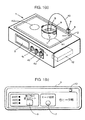
本発明の第1の実施の形態について、図1〜図4を参照して説明する。図1は本第1の実施形態の加熱調理装置であるガラストップ式電気コンロの外観図、図2は図1に示した電気コンロの回路図、図3は図1に示した電気コンロの温調動作のフローチャート、図4は電気コンロのヒータ部を上から見た図である。
【0019】
図1aを参照して、本実施形態の電気コンロ本体1は、加熱手段として、ガラストップ2の下方に設けられた右ヒータH1及び左ヒータH2と、グリル室3内に備えた図示しないグリルヒータH3とを備える。そして、使用者が加熱量調節つまみ4a,4b,4cを操作することで、右ヒータH1,左ヒータH2,グリルヒータH3の加熱動作の開始と停止、及び加熱量の調節がそれぞれ行われる。
【0020】
右ヒータH1は温調機能を有し、使用者により温調目標温度が温度設定器5で設定される。温度設定器5は、図1bに示すように、温調目標温度を160℃,180℃,200℃の3段階に設定する温度スイッチ6と、右ヒータH1の加熱制御モードを、温調を行う温調モードと温調を行わない通常モードとに切替えるモード切替スイッチ7とを備える。また、右ヒータH1は、中心を共通とする2個の図示しないリング形状の発熱体(本発明の加熱手段)によって構成され、使用者はダブルゾーン切換スイッチ13の操作により、外側の発熱体の使用/不使用を切換えることができる。
【0021】
本発明の温度センサであるサーミスタ11は、電気コンロ本体1に備えられたジャック8と、ジャック8に挿入接続されるプラグ9と、一端がプラグ9と接続され、他端がサーミスタ11と接続されたケーブル10を介して電気本体1と接続される。そして、サーミスタ11は、調理容器Aに入れられた被調理物Bに浸漬して使用され、調理物Bの温度を検出する。
【0022】
電気コンロ本体1に備えられた電子ユニット12は、モード切換スイッチ7の設定が温調モードであり、使用者が加熱量調節つまみ4aを加熱停止位置から加熱位置に操作したときに、右ヒータH1の温調制御を開始し、温度スイッチ6により設定された目標温度と、サーミスタ11により検出された被調理物Bの温度とが一致するように、右ヒータH1の加熱量を調節する。
【0023】
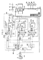
次に、図2を参照して電気本体1の動作について説明する。図2は電気コンロ本体1の回路図であり、電子ユニット12により右ヒータH1,左ヒータH2,グリルヒータH3を制御する構成となっている。
【0024】
電気コンロ本体1は端子台Tを介してプラグPと接続され、使用者がプラグPを図示しないコンセントに差込み、電源スイッチ48を操作することで、電子ユニット12に交流電圧が供給され、また、図1aに示した加熱量調節つまみ4a,4b,4cの操作にそれぞれ対応してON,OFFされる加熱量調節スイッチ25a,25b,25cを介して右ヒータH1,左ヒータH2,グリルヒータH3に交流電圧が供給される。
【0025】
右ヒータH1は、本発明の加熱手段である内外二重に配置されたリング形状の発熱体21a,21bを有し、内側の発熱体21aはリレーR5の作動接点50のON(閉)/OFF(開)により作動と停止がなされ、外側の発熱体21bはリレーR4の作動接点22のON(閉)/OFF(開)により作動と停止がなされる。尚、23はダブルゾーンスイッチ13の操作と連動して外側の発熱体21bへの電源供給を遮断する接点である。
【0026】
それぞれの発熱体21a,21b,21c,21dには、バイメタルスイッチである加熱防止スイッチ24が接続され、各発熱体の発熱量が所定値以上となったときに、それぞれに接続された加熱防止スイッチ24がON(開)して、各発熱体が異常加熱することを防止している。
【0027】
加熱量調節スイッチ25a,25b,25cは、上述したように、それぞれ図1aに示した加熱量調節つまみ4a,4b,4cの操作と連動して作動し、3個の接点26,27,28とバイメタルヒータ29とにより構成される。
【0028】
使用者が加熱量調節つまみ4aを加熱停止位置から加熱位置にセットすると、加熱量調節スイッチ25aの接点26,27,28がON(閉)する。接点27,28がONすることで発熱体21a,21bに電源が供給され、接点26がON(閉)することで使用者が加熱量調節つまみ4aを操作したことが電子ユニット12に認識される。
【0029】
バイメタルヒータ29は、ヒータとバイメタルがセットになったものであり、接点28と連動して作動する。バイメタルヒータ29のヒータ部への通電発熱により、バイメタルヒータ29のバイメタル部が変形すると、接点28がOFF(開)されて、発熱体21a,21b,及びバイメタルヒータ29のヒータ部への通電が遮断される。そして、バイメタルヒータ29のバイメタル部が徐々に冷えて元の形に戻ると接点28が再びON(閉)し、発熱体21a,21bへの通電が再開される。
【0030】
バイメタルヒータ29のバイメタル部の作動位置(バイメタルの変形により接点28がOFFされる位置)の設定は、加熱量調節つまみ4aの回転設定位置に応じて変更される。バイメタルの変形量は、バイメタルの温度の上昇に応じて大きくなるので、バイメタルヒータ29のバイメタル部の作動位置を変更することで、発熱体21a,21bへの通電率(所定時間あたりの通電時間)を変化させることができる。
【0031】
尚、加熱量調節スイッチ25b,25cの構成及び動作は、加熱量調節スイッチ25aと同じであり、加熱量調節つまみ4b,4cの操作に応じて、加熱量調節スイッチ25b,25cがそれぞれ作動する。
【0032】
また、電気コンロ本体1には、右ヒータH1、左ヒータH2の発熱によりガラストップ2が高温になっていることを使用者に注意する高温注意ランプ40が設けられ、右ヒータH1の発熱によりバイメタル接点41がONして高温注意ランプ40のランプ42が点灯し、左ヒータH2の発熱によりバイメタル接点43がONして高温注意ランプ40のランプ44が点灯する。
【0033】
電子ユニット12は、温調制御手段30と、リレーR1〜R5と、ブザー32とを備える。リレーR1,R2,R3は、それぞれ右ヒータH1,左ヒータH2,グリルヒータH3への電源供給のON/OFFを切換えるためのものである。即ち、リレーR1のコイルに通電がなされると、リレーR1の作動接点33がON(閉)して右ヒータH1に電源が供給され、リレーR1のコイルへの通電が遮断されると、リレーR1の作動接点33がOFF(開)して右ヒータH1への電源が遮断される。
【0034】
リレーR2,R3についても同様に、リレーR2,R3のコイルへの通電と通電遮断に応じて、リレーR2の作動接点34とリレーR3の作動接点35とがそれぞれON/OFFし、左ヒータH2とグリルヒータH3への電源が供給/遮断される。
【0035】
電子ユニット12に接続された電源ランプ36は、電源スイッチ48がON状態にあるときに点灯し、右ヒータランプ37,左ヒータランプ38,グリルヒータランプ39は、加熱量調節スイッチ25a,25b,25cの接点26がON(閉)状態にあるときにそれぞれ点灯する。また、ブザー32は、警告音により使用者に装置の異常等を報知するものである。
【0036】
温調制御手段30は、右ヒータH1の温調制御を行うためのものであり、温度設定器5に備えられた温度スイッチ6により使用者が設定した目標温度と、サーミスタ11による検出温度とが一致するように、発熱体21a(内側)と21b(外側)の作動と停止を行う。
【0037】
即ち、リレーR4のコイルに通電することでリレーR4の作動接点22をON(閉)して外側の発熱体21bを作動させ、リレーR4のコイルへの通電を遮断することでリレーR4の作動接点22をOFF(開)して外側の発熱体21bの作動を停止する。同様に、R5の作動接点50のON/OFFにより、内側の発熱体21aの作動と停止を行う。
【0038】
尚、本第1の実施の形態のように、2個の発熱体を配置したときには、本発明の所定番目は第1番目を意味する。
【0039】
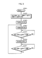
以下、図3を参照して、温調制御手段30による被調理物の温調制御動作について説明する。使用者が、モード切替スイッチ(図1b参照)7により右ヒータH1の加熱制御モードを温調モードに切替え、温度設定スイッチ6により希望温度を設定して、加熱量調節つまみ4aを加熱停止位置から加熱位置に操作すると、温調制御手段30による右ヒータH1の温調制御が開始される。
【0040】
温調制御手段30は、先ずSTEP2で、温度設定スイッチ6による設定温度に応じて、温調オフ温度と温調オン温度(温調オフ温度>温調オン温度)を決定する。
【0041】
次に、STEP3で内側の発熱体21aを作動を開始し、STEP4で外側の発熱体21bの作動を開始する。これにより、調理物Bの加熱が開始され、サーミスタ11の検出温度が上昇する。そして、STEP5で、サーミスタ11による調理物Bの検出温度が温調オフ温度以上となったときは、STEP6で外側の発熱体21bの作動を停止する。
【0042】
外側の発熱体21bの作動を停止することで、調理物Bに対する加熱量が減少し、サーミスタ11の検出温度が徐々に下がる。そして、STEP7でサーミスタ11の検出温度が温調オン温度未満となったときは、STEP4に戻って外側の発熱体21bの作動を再開する。
【0043】
このように、STEP4からSTEP7のループを繰り返すことで、調理物Bの温度は、ほぼ温調オン温度から温調オフ温度の範囲に保たれる。そして、外側の発熱体21bが停止されたときも、内側の発熱体21aは作動を継続するので、発熱体21aの加熱により調理物Bの温度低下が抑制される。そのため、温調制御中の調理物Bの温度変動を安定させることができる。
【0044】
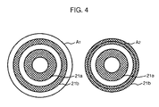
また、図4に示したように、調理容器がA1 のように大きく、発熱体21aと21b上に完全に載り切る場合は問題とならないが、調理容器がA2 のように小さく、外側の発熱体21bに載り切らない場合には、外側の発熱体21bの熱効率(調理容器が受ける熱量/発熱体21bの発熱量)が低くなる。
【0045】
そのため、この場合に、熱効率の低い外側の発熱体21bの作動を継続した状態で、内側の発熱体21aを作動/停止させて温調を行うと、熱効率の低い外側の発熱体21bが常時作動し、電力が無駄に消費されてしまう。
【0046】
これに対して、上述したように、逆に熱効率の高い内側の発熱体21aの作動を継続した状態で、熱効率の低い外側の発熱体21bを作動/停止させて温調を行ったときには、熱効率の低い外側の発熱体21bを作動させる時間が少なくなるので、温調制御時の消費電力を減少させることができる。
【0047】
次に、本発明の第2の実施の形態について説明する。本第2の実施の形態の装置構成は、上述した第1の実施の形態と同様であり、温調制御手段30による温調制御動作が異なる。
【0048】
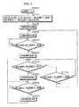
以下、図5を参照して、本第2の実施の形態における温調制御手段30の動作を説明する。
【0049】
温調制御手段30は、上述した第1の実施の形態と同様の手順で、使用者により温調モードでの右ヒータH1の加熱開始の指示がなされると、STEP21で、温度設定スイッチ6による設定温度に応じて、第1温調オフ温度,第1温調オン温度,第2温調オフ温度,第2温調オン温度(第2温調オフ温度>第1温調オフ温度>第2温調オン温度>第1温調オン温度)を決定する。
【0050】
そして、STEP22で内側の発熱体21aを作動させ、STEP23で外側の発熱体21bを作動させて調理物Bの加熱を開始する。加熱開始後、サーミスタ11による調理物Bの検出温度が第1温調オフ温度以上となったときは、STEP24からSTEP25に進み、STEP25で外側の発熱体21bの作動を停止して、右ヒータH1の総加熱量を減少させる。
【0051】
そして、STEP26で、サーミスタ11による調理物Bの検出温度が第2温調オフ温度以上であるときは、STEP27で内側の発熱体21aの作動を停止して、右ヒータH1の総加熱量を更に減少(この場合は0)させ、STEP28でサーミスタ11による調理物Bの検出温度が第2オン温度未満まで下がるのを待つ。
【0052】
STEP28で、サーミスタ11による調理物Bの検出温度が第2温調オン温度未満まで下がったときには、STEP29に進んで内側の発熱体21aを作動させることで右ヒータ総加熱量を増加させ、STEP26に戻る。
【0053】
右ヒータH1の、内側の発熱体21aによる調理物Bに対する発熱量が、調理物Bの自然放熱量を上回ったときは、調理物Bの温度が上昇するため、STEP26で、サーミスタ11による調理物Bの検出温度が第2温調オフ温度以上となり、STEP27に進む。このように、STEP26〜STEP29のループが繰り返し実行されるので、調理物Bの温度がほぼ第2温調オン温度から第2温調オフ温度までの範囲に保たれる。
【0054】
一方、右ヒータH1の、内側の発熱体21aによる被調理物Bに対する発熱量が、被調理物Bの自然放熱量を下回ったときには、調理物Bの温度が下降するため、STEP26,STEP30のループのSTEP30からSTEP23に進み、STEP23で外側の発熱体21bを作動させて右ヒータH1の総加熱量を増加させる。この場合には、調理物Bの温度がほぼ第1温調オン温度から第2温調オン温度までの範囲に保たれる。
【0055】
このように、本第2の実施の形態では、右ヒータH1の総加熱量を減少させるときは、外側の発熱体21bから内側の発熱体21aの順に、その作動を停止し、また、右ヒータH1の総加熱量を増加させるときは、内側の発熱体21aから外側の発熱体21bの順に作動させる。
【0056】
そのため、図4に示したように、調理容器A2 が小さく、外側の発熱体21bに完全に載り切らず、外側の発熱体21bの熱効率(調理容器A2 が受ける熱量/発熱体21bの発熱量)が小さいときに、熱効率の大きい内側の発熱体21aが優先的に使用され、電力消費を抑制して、調理物Bの加熱を行うことができる。
【0057】
尚、上述した第1、第2の実施の形態では、リング形状の発熱体が2個配置された電気コンロを例に説明したが、発熱体が3個以上配置された電気コンロであってもよい。この場合には、本発明の所定番目は、発熱体の個数、各発熱体の発熱量、大きさ等に応じて決定される。
【0058】
また、上述した第1、第2の実施の態様では、加熱手段として電気による発熱体を示したが、ガスバーナ等の他の加熱手段であってもよい。
【図面の簡単な説明】
【図1】ガラストップ式電気コンロの外観図。
【図2】図1に示した電気コンロの回路図。
【図3】図1に示した電気コンロの温調動作のフローチャート。
【図4】図1に示した電気コンロの上面図。
【図5】図1に示した電気コンロの温調動作のフローチャート。
【符号の説明】
1…電気コンロ本体、2…ガラストップ、3…グリル室、4…加熱量調節つまみ、5…温度設定器、6…温度スイッチ、7…モード切換スイッチ、8…ジャック、9…プラグ、10…接続ケーブル、11…サーミスタ、12…電子ユニット、13…ダブルゾーン切換スイッチ、H1…右ヒータ、H2…左ヒータ、H3…グリルヒータ、21a,21b,21c,21d…発熱体、25a,25b,25c…加熱量調節スイッチ、30…温調制御手段[0001]
TECHNICAL FIELD OF THE INVENTION
The present invention relates to a cooking device for heating an object to be cooked.
[0002]
[Prior art]
2. Description of the Related Art Conventionally, an electric stove, which is a heating cooking device, includes a heater as a heating means, and a cooking vessel such as a pot is placed on the heater to perform heating cooking.
[0003]
In addition, an electric stove having a temperature control function is also known. In this electric stove, a temperature sensor for detecting the temperature of the object to be cooked is provided, and the temperature detected by the temperature sensor matches a predetermined target temperature. That is, the so-called temperature control is performed to adjust the heating amount of the heater. Thus, the user can set the desired temperature and select the temperature-controlled cooking mode, so that cooking can be performed while keeping the temperature of the food constant, and, for example, tempura cooking can be easily performed.
[0004]
Here, for example, in an electric stove provided with a double ring heater inside and outside having a common center, the above-mentioned temperature control generally includes a temperature control off temperature according to a target temperature and a temperature control off temperature that is higher than the temperature control off temperature. A temperature control on temperature set to a low temperature is determined, and when the detected temperature of the object to be cooked by the temperature sensor becomes equal to or higher than the temperature control off temperature, the operation of both the inner and outer heaters is interrupted and interrupted. Thereafter, when the detected temperature of the object to be cooked by the temperature sensor becomes equal to or lower than the temperature adjustment ON temperature, the operation is performed by restarting both the inner and outer heaters.
[0005]
However, when the temperature control is performed by simultaneously operating and stopping all the heaters as described above, the temperature of the food increases and decreases at a high speed, and the temperature of the object to be cooked becomes the temperature control off temperature and the temperature control on. Since it fluctuates with the temperature in a short cycle, smooth temperature control cannot be performed. Further, in the case where the operation of the heater is started and stopped via the contact relay, there is a disadvantage that the life of the relay is shortened due to frequent switching of the relay.
[0006]
In addition, in order to perform smooth temperature control, it is conceivable to control the amount of heating of the heater by adjusting the amount of electricity to the heater, but in this case, the circuit for controlling the electricity to the heater becomes complicated, There is a disadvantage that the manufacturing cost increases.
[0007]
In order to eliminate such inconveniences, in an electric stove provided with double heaters inside and outside, the operation and stop of each heater are individually controlled, and the temperature of the object to be cooked by the temperature sensor is set to be equal to or higher than the temperature control off temperature. In such a case, it is conceivable to stop the operation of only one of the two heaters and reduce the total amount of heating of the heaters to perform temperature control.
[0008]
However, when the detected temperature of the object to be cooked becomes equal to or higher than the temperature control off temperature as described above, when the temperature control is performed by stopping the operation of only the inner heater, It has been found that the following disadvantages occur.
[0009]
That is, if the size (bottom area) of the cooking container in which the object to be cooked is small, the cooking container may not be able to completely cover the outer heater. If the operation of the inner heater is stopped when the temperature becomes equal to or higher than the temperature adjustment off temperature, the object to be cooked is kept warm only by the outer heater on which the cooking container is not completely mounted.
[0010]
Therefore, in this case, the ratio of the amount of heat received by the cooking vessel to the total amount of heat generated by the heater (thermal efficiency) is small, power is wasted, and the effect of suppressing a decrease in the temperature of the object to be cooked (thermal effect) is also obtained. It has been found that there is a disadvantage of being smaller.
[0011]
[Problems to be solved by the invention]
SUMMARY OF THE INVENTION It is an object of the present invention to provide a heating and cooking device in which the heating means has good thermal efficiency when performing temperature control on an object to be cooked.
[0012]
[Means for Solving the Problems]
In order to achieve the above object, a first embodiment of the present invention has a plurality of ring-shaped heating means having a common center, a temperature sensor for detecting the temperature of the object to be heated by the heating means, Temperature control means for performing temperature control control for adjusting the total heating amount of the plurality of heating means so that the temperature of the object detected by the temperature sensor matches a predetermined target temperature. In the device, the temperature control control means determines a temperature control off temperature and a temperature control on temperature that is a temperature lower than the temperature control off temperature according to the target temperature, and controls the temperature of the object to be cooked by the temperature sensor. When the detected temperature becomes equal to or higher than the temperature control off temperature, the operation of the heating means outside the predetermined number from the center is interrupted, and only the heating means inside the predetermined number is operated, and then the Temperature sensor When the output temperature is equal to or less than the on temperature, and performs temperature control of the food by resuming the operation of the outside of the heating means than the prescribed order.
[0013]
According to the present invention, when the detected temperature of the object to be cooked by the temperature sensor becomes equal to or higher than the temperature control off temperature, the operation of the heating means outside the predetermined number is stopped, and the inside of the heating means is stopped from the predetermined number. The cooking object is heated only by the heating means (temperature control OFF period), and thereafter, when the detected temperature of the cooking object by the temperature sensor becomes equal to or lower than the temperature adjustment ON temperature, heating is performed by all heating means. Heat the food (temperature control on period).
[0014]
As a result, the temperature of the object to be cooked does not drop rapidly as in the case where all the heaters are turned off at the same time, and smooth temperature control can be performed. Further, even when heating the object to be cooked by using a cooking container that does not completely stand on the outer heating means, the cooking container is located inside the predetermined number during the temperature control off period. Since the heating is performed by the heater, the heat efficiency (the amount of heat received by the cooking vessel / the total amount of heat generated by the heater) is good, and the temperature of the object to be cooked can be suppressed with a small amount of heat.
[0015]
Further, a second embodiment of the present invention comprises a plurality of ring-shaped heating means having a common center, a temperature sensor for detecting the temperature of the object to be heated by the heating means, and a temperature sensor for detecting the temperature of the object to be cooked by the heating means. A heating control device that performs temperature control control that adjusts a total heating amount of the plurality of heating devices so that the temperature of the object to be cooked matches a predetermined target temperature. The tone control means stops the operation of the heating means in order from the outside to the inside when decreasing the total heating amount of the plurality of heating means, and increases the inside heating when increasing the total heating amount of the plurality of heating means. The operation of the heating means is started sequentially from the outside to the outside.
[0016]
According to the present invention, when reducing the total heating amount of the plurality of heating means, the operation is stopped from the outer heating means. When the total heating amount of the plurality of heating means is increased, the operation is started from the inner heating means.
[0017]
Therefore, when heating a cooking container having a small bottom area, the total heating amount can be adjusted after preferentially using the heating means of the portion on which the cooking container is placed. As a result, similarly to the first embodiment, the thermal efficiency of the heating means (the amount of heat received by the cooking vessel / the total amount of heat generated by the heating means) is good, and the decrease in the temperature of the object to be cooked can be suppressed with a small amount of heat. .
[0018]
BEST MODE FOR CARRYING OUT THE INVENTION
A first embodiment of the present invention will be described with reference to FIGS. FIG. 1 is an external view of a glass-top type electric stove, which is a cooking device according to the first embodiment, FIG. 2 is a circuit diagram of the electric stove shown in FIG. 1, and FIG. 3 is a temperature diagram of the electric stove shown in FIG. FIG. 4 is a flowchart of the adjusting operation, and FIG. 4 is a view of the heater portion of the electric stove as viewed from above.
[0019]
Referring to FIG. 1A, electric stove body 1 of the present embodiment includes, as heating means, right heater H1 and left heater H2 provided below glass top 2, and a grill heater (not shown) provided in
[0020]
The right heater H1 has a temperature control function, and a temperature control target temperature is set by the
[0021]
The
[0022]
The
[0023]
Next, the operation of the electric main body 1 will be described with reference to FIG. FIG. 2 is a circuit diagram of the electric stove main body 1, and has a configuration in which the
[0024]
The electric stove main body 1 is connected to a plug P via a terminal block T, and a user inserts the plug P into an outlet (not shown) and operates a
[0025]
The right heater H1 has ring-shaped
[0026]
A
[0027]
As described above, the heating
[0028]
When the user sets the heating
[0029]
The
[0030]
The setting of the operating position of the bimetal portion of the bimetal heater 29 (the position where the
[0031]
The configuration and operation of the heating amount adjustment switches 25b and 25c are the same as those of the heating amount adjustment switch 25a, and the heating amount adjustment switches 25b and 25c are operated according to the operation of the heating amount adjustment knobs 4b and 4c, respectively.
[0032]
Further, the electric stove main body 1 is provided with a high-
[0033]
The
[0034]
Similarly, for the relays R2 and R3, the operating
[0035]
The
[0036]
The temperature control means 30 is for controlling the temperature of the right heater H1. The target temperature set by the user with the
[0037]
That is, by energizing the coil of the relay R4, the operating
[0038]
When two heating elements are arranged as in the first embodiment, the predetermined number of the present invention means the first.
[0039]
Hereinafter, with reference to FIG. 3, a description will be given of a temperature control control operation of the object to be cooked by the
[0040]
The temperature control control means 30 first determines the temperature control off temperature and the temperature control on temperature (temperature control off temperature> temperature control on temperature) according to the temperature set by the
[0041]
Next, the operation of the
[0042]
By stopping the operation of the
[0043]
In this way, by repeating the loop from STEP 4 to
[0044]
Also, as shown in FIG. 4, if the cooking container is large as A1, and it does not matter if the cooking container is completely mounted on the
[0045]
Therefore, in this case, if the temperature control is performed by operating / stopping the
[0046]
On the other hand, as described above, when the temperature control is performed by operating / stopping the
[0047]
Next, a second embodiment of the present invention will be described. The device configuration of the second embodiment is the same as that of the above-described first embodiment, and the temperature control operation by the
[0048]
Hereinafter, with reference to FIG. 5, the operation of the
[0049]
When the user issues an instruction to start heating the right heater H1 in the temperature adjustment mode in the same procedure as in the first embodiment, the temperature
[0050]
Then, the
[0051]
Then, in
[0052]
When the detected temperature of the food B by the
[0053]
When the calorific value of the right heater H1 with respect to the food B by the
[0054]
On the other hand, when the calorific value of the right heater H1 with respect to the cooking object B by the
[0055]
As described above, in the second embodiment, when the total heating amount of the right heater H1 is reduced, the operation is stopped in order from the
[0056]
Therefore, as shown in FIG. 4, the cooking container A2 is small and does not completely fit on the
[0057]
In the first and second embodiments described above, the electric stove in which two ring-shaped heating elements are arranged has been described as an example. However, an electric stove in which three or more heating elements are arranged may be used. Good. In this case, the predetermined number of the present invention is determined according to the number of heating elements, the amount of heat generated by each heating element, the size, and the like.
[0058]
Further, in the first and second embodiments described above, an electric heating element is shown as the heating means, but another heating means such as a gas burner may be used.
[Brief description of the drawings]
FIG. 1 is an external view of a glass-top type electric stove.
FIG. 2 is a circuit diagram of the electric stove shown in FIG.
FIG. 3 is a flowchart of a temperature control operation of the electric stove shown in FIG. 1;
FIG. 4 is a top view of the electric stove shown in FIG. 1;
5 is a flowchart of a temperature control operation of the electric stove shown in FIG.
[Explanation of symbols]
DESCRIPTION OF SYMBOLS 1 ... Electric stove main body, 2 ... Glass top, 3 ... Grill room, 4 ... Heating amount adjustment knob, 5 ... Temperature setting device, 6 ... Temperature switch, 7 ... Mode changeover switch, 8 ... Jack, 9 ... Plug, 10 ... Connection cable, 11: Thermistor, 12: Electronic unit, 13: Double zone switch, H1: Right heater, H2: Left heater, H3: Grill heater, 21a, 21b, 21c, 21d: Heating element, 25a, 25b, 25c ... heating amount adjustment switch, 30 ... temperature control control means
Claims (2)
前記温調制御手段は、前記目標温度に応じて温調オフ温度と、該温調オフ温度よりも低い温度である温調オン温度とを決定し、
前記温度センサによる被調理物の検出温度が前記温調オフ温度以上となったときに、中心から所定番目よりも外側の前記加熱手段の作動を中断して、該所定番目から内側の前記加熱手段のみを作動させ、その後、前記温度センサによる被調理物の検出温度が前記オン温度以下となったときに、前記所定番目よりも外側の前記加熱手段の作動を再開させることで前記温調制御を行うことを特徴とする加熱調理装置。A plurality of ring-shaped heating means having a common center, a temperature sensor for detecting a temperature of the food to be heated by the heating means, a temperature of the food to be detected by the temperature sensor and a predetermined target temperature And a temperature control control means for performing a temperature control control for adjusting a total heating amount of the plurality of heating means so as to match.
The temperature control control means determines a temperature control off temperature and a temperature control on temperature that is lower than the temperature control off temperature according to the target temperature,
When the temperature of the object to be cooked detected by the temperature sensor is equal to or higher than the temperature control off temperature, the operation of the heating means outside the predetermined number from the center is interrupted, and the heating means inside the predetermined number is stopped. Only after that, when the detected temperature of the object to be cooked by the temperature sensor becomes equal to or lower than the ON temperature, the temperature control is resumed by restarting the operation of the heating means outside the predetermined number. A cooking device characterized by performing.
前記温調制御手段は、前記複数の加熱手段の総加熱量を減少させるときは、外側から内側に向けて順次加熱手段の作動を停止し、前記複数の加熱手段の総加熱量を増加させるときには、内側から外側に向けて順次加熱手段の作動を開始することを特徴とする加熱調理装置。A plurality of ring-shaped heating means having a common center, a temperature sensor for detecting a temperature of the food to be heated by the heating means, a temperature of the food to be detected by the temperature sensor and a predetermined target temperature And a temperature control control means for performing a temperature control control for adjusting a total heating amount of the plurality of heating means so as to match.
When decreasing the total heating amount of the plurality of heating units, the temperature control control unit sequentially stops the operation of the heating units from the outside toward the inside, and increases the total heating amount of the plurality of heating units. A heating device for sequentially starting the operation of the heating means from the inside to the outside.
Priority Applications (1)
| Application Number | Priority Date | Filing Date | Title |
|---|---|---|---|
| JP25659897A JP3563243B2 (en) | 1997-09-22 | 1997-09-22 | Cooking device |
Applications Claiming Priority (1)
| Application Number | Priority Date | Filing Date | Title |
|---|---|---|---|
| JP25659897A JP3563243B2 (en) | 1997-09-22 | 1997-09-22 | Cooking device |
Publications (2)
| Publication Number | Publication Date |
|---|---|
| JPH1194261A JPH1194261A (en) | 1999-04-09 |
| JP3563243B2 true JP3563243B2 (en) | 2004-09-08 |
Family
ID=17294864
Family Applications (1)
| Application Number | Title | Priority Date | Filing Date |
|---|---|---|---|
| JP25659897A Expired - Fee Related JP3563243B2 (en) | 1997-09-22 | 1997-09-22 | Cooking device |
Country Status (1)
| Country | Link |
|---|---|
| JP (1) | JP3563243B2 (en) |
-
1997
- 1997-09-22 JP JP25659897A patent/JP3563243B2/en not_active Expired - Fee Related
Also Published As
| Publication number | Publication date |
|---|---|
| JPH1194261A (en) | 1999-04-09 |
Similar Documents
| Publication | Publication Date | Title |
|---|---|---|
| US6427581B1 (en) | Waffle maker with cooking temperature control | |
| JP3563243B2 (en) | Cooking device | |
| JP2008180472A (en) | Cooker | |
| CN220958560U (en) | Oven with a baking oven | |
| JP3563238B2 (en) | Cooking device | |
| JP3524730B2 (en) | Cooking device | |
| JP5134790B2 (en) | Electric heater | |
| JP3217725B2 (en) | Cooking device | |
| JP3556435B2 (en) | Gas cooker | |
| JP4158115B2 (en) | Electric cooker | |
| KR101597548B1 (en) | Electric cooker | |
| JPH0789989B2 (en) | Electric rice cooker | |
| KR20020072987A (en) | Gas oven range | |
| JP2890388B2 (en) | rice cooker | |
| JP4302682B2 (en) | Cooker | |
| JPH10225370A (en) | Heat cooking system | |
| JPH0425450B2 (en) | ||
| JPH08189643A (en) | Table stove with grill | |
| JPH078372A (en) | Rice cooker | |
| JP4234332B2 (en) | Electronics | |
| KR100312896B1 (en) | Microwave oven and controlling method for selecting mode thereof | |
| WO2026043444A1 (en) | A temperature control method for a cooking appliance and a system related thereto | |
| JP2003217796A (en) | Vehicle seat heater | |
| KR20000033879A (en) | Surge voltage prevention circuit of high voltage transformer | |
| JPH04325122A (en) | Rice cooker |
Legal Events
| Date | Code | Title | Description |
|---|---|---|---|
| A131 | Notification of reasons for refusal |
Free format text: JAPANESE INTERMEDIATE CODE: A131 Effective date: 20040210 |
|
| TRDD | Decision of grant or rejection written | ||
| A01 | Written decision to grant a patent or to grant a registration (utility model) |
Free format text: JAPANESE INTERMEDIATE CODE: A01 Effective date: 20040601 |
|
| A61 | First payment of annual fees (during grant procedure) |
Free format text: JAPANESE INTERMEDIATE CODE: A61 Effective date: 20040602 |
|
| R150 | Certificate of patent or registration of utility model |
Free format text: JAPANESE INTERMEDIATE CODE: R150 |
|
| FPAY | Renewal fee payment (event date is renewal date of database) |
Free format text: PAYMENT UNTIL: 20090611 Year of fee payment: 5 |
|
| FPAY | Renewal fee payment (event date is renewal date of database) |
Free format text: PAYMENT UNTIL: 20100611 Year of fee payment: 6 |
|
| FPAY | Renewal fee payment (event date is renewal date of database) |
Free format text: PAYMENT UNTIL: 20100611 Year of fee payment: 6 |
|
| FPAY | Renewal fee payment (event date is renewal date of database) |
Free format text: PAYMENT UNTIL: 20110611 Year of fee payment: 7 |
|
| FPAY | Renewal fee payment (event date is renewal date of database) |
Free format text: PAYMENT UNTIL: 20110611 Year of fee payment: 7 |
|
| FPAY | Renewal fee payment (event date is renewal date of database) |
Free format text: PAYMENT UNTIL: 20120611 Year of fee payment: 8 |
|
| FPAY | Renewal fee payment (event date is renewal date of database) |
Free format text: PAYMENT UNTIL: 20130611 Year of fee payment: 9 |
|
| R250 | Receipt of annual fees |
Free format text: JAPANESE INTERMEDIATE CODE: R250 |
|
| R250 | Receipt of annual fees |
Free format text: JAPANESE INTERMEDIATE CODE: R250 |
|
| R250 | Receipt of annual fees |
Free format text: JAPANESE INTERMEDIATE CODE: R250 |
|
| R250 | Receipt of annual fees |
Free format text: JAPANESE INTERMEDIATE CODE: R250 |
|
| LAPS | Cancellation because of no payment of annual fees |