JP3557413B2 - LSP parameter decoding apparatus and decoding method - Google Patents
LSP parameter decoding apparatus and decoding method Download PDFInfo
- Publication number
- JP3557413B2 JP3557413B2 JP2002110037A JP2002110037A JP3557413B2 JP 3557413 B2 JP3557413 B2 JP 3557413B2 JP 2002110037 A JP2002110037 A JP 2002110037A JP 2002110037 A JP2002110037 A JP 2002110037A JP 3557413 B2 JP3557413 B2 JP 3557413B2
- Authority
- JP
- Japan
- Prior art keywords
- quantization
- decoding
- value
- lsp parameter
- error
- Prior art date
- Legal status (The legal status is an assumption and is not a legal conclusion. Google has not performed a legal analysis and makes no representation as to the accuracy of the status listed.)
- Expired - Lifetime
Links
Images


Landscapes
- Compression, Expansion, Code Conversion, And Decoders (AREA)
Description
【0001】
【発明の属する技術分野】
本発明は、音声信号のスペクトル情報の特徴パラメータであるLSPパラメータの符号化復号化装置に関するものである。
【0002】
【従来の技術】
従来、4〜8kbqs程度のビットレートの音声符号化装置では、音声信号を分析することによってスペクトル情報と音源情報とに分離して符号化する方法が主流である。LSPパラメータは、スペクトル情報を表す特徴パラメータであり、通常、フレームあたり10次程度必要である。LSPパラメータを符号化する最も基本的な方法としては、個々の値をスカラーとして量子化する方法があるが、量子化効果が低いため、複数のLSPパラメータをまとめて量子化するベクトル量子化が良く用いられる。また、LSPパラメータは、隣接するフレーム間に大きな相関があるため、フレーム間の相関を利用することによって、量子化効率を上げることができる。
【0003】
図6は従来のフレーム間の相関を利用するLSPパラメータ量子化装置の構成を示すブロック図であり、600はLSPパラメータ算出手段、601は過去の量子化値を蓄えておくバッファ、602は過去の量子化値から現フレームの値を線形に予測する予測手段、603は予測値と入力値との誤差を最小にする符号を符号帳から選択する誤差最小化手段、604は符号帳、605は出力符号から量子化値を復号する復号化手段である。また、606は入力音声信号、607は現フレームのLSPパラメータ、608は出力符号、609は現フレームの量子化値、610は過去の量子化値、611は予測された現フレームのLSPパラメータである。
【0004】
以上のように、構成された従来のLSPパラメータ量子化装置における処理について説明する。LSPパラメータ算出手段600は、入力音声信号606から現フレームのLSPパラメータ607を算出する。予測手段602はバッファ601に蓄えられた過去の量子化値610から現フレームのLSPパラメータを線形に予測する。誤差最小化手段603は、入力音声信号から算出されたLSPパラメータ607と、過去の量子化値から予測されたLSPパラメータ611の誤差を算出し、誤差を最小にする符号を符号帳604から選択し、その符号を出力する。復号手段605は、出力符号608から量子化値を復号し、復号された量子化値609は、バッファ601に格納される。
【0005】
【発明が解決しようとする課題】
しかしながら、上記従来の装置では、入力音声信号が定常に近い状態では、高い予測ゲインが得られ、精度の高い量子化が行なえるものの、入力音声信号が過渡的な状態では、予測ゲインが低下し、量子化の精度も低下する。フレーム長が長くなると、隣接フレーム間で過渡的要素が大きくなり、フレーム間相関が小さくなるため、同様に予測ゲインが低下する。したがって、隣接フレーム間相関を利用して予測を行なう量子化方法は、入力音声信号が隣接フレーム間で定常とみなされやすく、フレーム長の短い音声符号化方法には適するが、フレーム長が長い音声符号化方法に適用するのは難しかった。
【0006】
また、過去の量子化値から現在の値を予測するため、伝送路で生じる符号誤りの影響が、誤りフレームだけではなく以降のフレームに伝搬するため、誤りに弱いという問題があった。
【0007】
本発明は、上記従来の問題を解決するものであり、入力音声信号が過渡的な状態でも、高い量子化精度を確保するとともに、誤りに対する耐性を高めることのできるLSPパラメータ復号化装置及び復号化方法を提供することを目的とする。
【0008】
【課題を解決するための手段】
本発明は、上記目的を達成するために、音声信号のスペクトル情報の特徴パラメータであるLSPパラメータを復号化する復号化装置であって、フレーム単位で独立にベクトル量子化されたLSPパラメータを復号化して量子化値を得る第1の復号化手段と、前記第1の復号化手段で得られた量子化値と参照フレームの量子化値から求めた予測値を用いてフレーム間の相関を利用してベクトル量子化されたLSPパラメータを復号化する第2の復号化手段とを備えたものである。
【0009】
また本発明は、音声信号のスペクトル情報の特徴パラメータであるLSPパラメータを復号化する復号化方法であって、フレーム単位で独立にベクトル量子化されたLSPパラメータを復号化する第1の復号化ステップと、前記第1の復号化ステップで得られた量子化値と参照フレームの量子化値から予測値を求め、この予測値を用いてフレーム間の相関を利用してベクトル量子化されたLSPパラメータを復号化する第2の復号化ステップの各処理動作によりLSPパラメータを復号化するようにしたものである。
【0010】
【作用】
したがって、本発明によれば、隣接フレーム間の相関が小さい部分では、フレーム単位で独立に復号化する第1の復号化手段を用い、隣接フレーム間の相関が大きい部分では、前記第1の復号化手段で得られた量子化値と参照フレームの量子化値から求めた予測値を用いてフレーム間の相関を利用してベクトル量子化されたLSPパラメータを復号化することにより、入力音声信号の状態に関わらず、安定した高い復号化精度が得ることができる。
【0011】
また本発明は、隣接フレーム間の相関を利用する復号化動作では、第1の復号化手段で得られた量子化値と参照フレームの量子化値から予測値を求め、この予測値を用いてフレーム間の相関を利用してベクトル量子化されたLSPパラメータを復号化することにより、伝送誤りに対する耐性を高めることができる。
【0012】
【発明の実施の形態】
(実施の形態1)
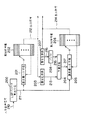
以下、本発明の第1の実施の形態を図を用いて説明する。図1は本発明の第1の実施の形態におけるLSPパラメータ符号化装置の構成を示すブロック図であり、100はLSPパラメータ算出手段、101はフレーム単位で独立に量子化を行なう第1の量子化手段、102は隣接フレーム間の相関を利用して量子化を行なう第2の量子化手段、103、104は復号化手段、105は誤差比較手段、106は量子化手段を切り換えるスイッチである。また、107は入力音声信号、108は算出したLSPパラメータ、109は第1の量子化手段101の出力符号、110は第2の量子化手段102の出力符号、111は第1の量子化手段101による量子化値、112は第2の量子化手段102による量子化値、113はスイッチ106の切り換えを制御する信号、114は出力符号である。
【0013】
次に、上記実施の形態の動作について説明する。LSPパラメータ算出手段100によって算出したLSPパラメータ108は、それぞれ第1の量子化手段101と、第2の量子化手段102に入力される。第1の量子化手段101は、フレーム単位で独立に量子化を行ない、符号109を出力する。同様に、第2の量子化手段102は、隣接フレーム間の相関を利用して量子化を行ない、符号110を出力する。復号化手段103は、符号109から第1の量子化手段101による量子化値111を復号し、復号化手段104は、符号110から第2の量子化手段102による量子化値112を復号する。誤差比較手段105は、量子化値111および112とLSPパラメータ108との誤差をそれぞれ算出、比較し、スイッチ106を切り換えることによって、誤差の小さい方の量子化手段を選択し、選択した量子化手段の出力符号をこの符号化装置の出力符号114として出力する。
【0014】
このように、本実施の形態によれば、入力音声信号の状態に関わらず安定した量子化精度が期待できる第1の量子化手段101と、入力音声信号が定常に近い状態で高い量子化精度が期待できる第2の量子化手段102の、2つの異なる量子化方法の量子化手段を切り換えて使用することにより、入力音声信号の状態に関わらず、高い安定した量子化精度を得ることができる。
【0015】
また、第2の量子化手段102は、隣接フレーム間の相関を利用して量子化を行なうため、伝送誤りにより影響が次フレーム以降に伝搬するが、第1の量子化手段101は、フレーム単位で独立に量子化を行なうため、誤りによる影響は伝搬しない。したがって、誤りによる影響の伝搬は、第2の量子化手段が連続して選択されている区間に限られ、第1の量子化手段が選択されたフレーム以降には伝搬しない。第1の量子化手段と第2の量子化手段とがそれぞれ選択される確率は、入力音声信号の性質によって大きく変化するが、通常の会話では1対1から1対2程度であり、どちらかの量子化手段が長い区間にわたって連続して選択されることは少ない。したがって、誤りによる影響の伝搬は短い区間に限定され、誤りによる影響が伝搬し続ける従来例に対して、誤りに対する耐性が高い。
【0016】
(実施の形態2)
図2は本発明の第2の実施の形態の構成を示すブロック図であり、図1の第2の量子化手段102の詳細を示すものである。200はLSPパラメータ算出手段であり、図1のLSPパラメータ算出手段100と同じものである。201は第1段目の誤差最小化手段、202は第1の符号帳、203、207は復号化手段、204は過去の量子化値から現フレームの値を線形に予測する予測手段、205は第2段目の誤差最小化手段、206は第2の符号帳、208は過去の量子化値を蓄えておくバッファである。また、210は入力音声信号、211は算出した現フレームのLSPパラメータ、212は第1段階の出力符号、213は第1段階の量子化値、214は第2段階の出力符号、215は現フレームの量子化値、216は過去の量子化値、217は予測された現フレームのLSPパラメータである。
【0017】
次に上記実施の形態の動作について説明する。LSPパラメータ算出手段200は、入力音声信号210から現フレームのLSPパラメータ211を算出する。第1段階として、第1段目の誤差最小化手段201は、第1の符号帳202からLSPパラメータ211との誤差が最小となる符号を選択し、出力符号212として出力する。第2段階として、予測手段204は、復号化手段203によって復号された第1段階の量子化値213と、バッファ208に蓄えられた過去の量子化値216とから現フレームのLSPパラメータ217を線形に予測する。第2段目の誤差最小化手段205は、予測されたLSPパラメータ217と入力音声信号210とから算出された現フレームのLSPパラメータ211との誤差が最小となる符号を、第2の符号帳206から選択し、出力符号214として出力する。復号化手段207は、出力符号214とから、現フレームの量子化値215を復号し、バッファ208に格納する。
【0018】
ここで、第2段階の処理を図3を用いて説明する。図3において、300は前フレームのLSPパラメータの量子化前の値、301は現フレームのLSPパラメータの量子化前の値、302は前フレームの量子化値、303は現フレームの第1段階の量子化値、304は現フレームの予測値、305は予測値と量子化前の値との誤差、306は現フレームの量子化値である。
【0019】
現フレームの予測値304は、前フレームの量子化値302と現フレームの第1段階の量子化値303を用いて、
pn =αqn−1 +(1−α)υn
よって、誤差305は、

【0020】
なお、予測係数αを固定とすることにより、第2段目の誤差最小化の処理は、誤差305に対して誤差が最小となる符号ベクトルを選択するのみとなり、演算量が削減される。
【0021】
このように、本実施の形態によれば、現フレームの予測値を、過去のフレームの情報と現フレームの情報とから予測するため、復号化する際に、過去のフレームの情報に伝送誤りによる影響があっても、現フレームの予測値に値する影響を低減することができ、伝送誤りに値する耐性を高めることができる。
【0022】
(実施の形態3)
図4は本発明の第3の実施の形態の構成を示すブロック図であり、上記第1および第2の実施の形態の符号化装置に対応する復号化装置の構成を示すものである。図4において、400は伝送誤り検出手段、401はスイッチ制御手段、402は第1の量子化手段による符号ベクトルを格納する符号帳、403は第2の量子化手段の第1段階による符号ベクトルを格納する符号帳、404は第2の量子化手段の第2段階による符号ベクトルを格納する符号帳、405は予測手段、406は復号化手段、407、408は復号化手段を切り換えるスイッチ、409は出力する復号値を切り換えるスイッチ、410は前フレームの量子化値を蓄えるバッファである。また、411は伝送符号、412は第1の量子化手段による量子化値、413は第2の量子化手段の第1段階での量子化値、414は現フレームの予測値、415は第2の量子化手段の第2段階での量子化値、416は復号化装置の出力量子化値である。
【0023】
次に上記実施例の動作について説明する。伝送符号が前記符号化装置における第1の量子化手段による符号であれば、スイッチ407、408を連動してa側に、第2の量子化手段による符号であれば、スイッチ407、408をb側に切り換えることによって、第1、第2のそれぞれの量子化手段に対応する復号手段で量子化値を復号することができる。第2の量子化手段による伝送を復号化する場合において、伝送符号に誤りがないフレームでは、スイッチ制御手段401は、スイッチ409のA、B、C、D、E、Fの6つの端子のうちA−B間と、C−D間を接続する。この状態では、各復号手段からの復号値は正しく復号されて出力される。伝送誤り検出手段400が伝送誤りを検出したフレームでは、スイッチ制御手段401は、スイッチ409の端子のうち、D−E間を接続する。この状態では、伝送符号411は無視され、バッファ410に蓄えられた前フレームの量子化値が出力される。伝送誤り検出手段400が誤りを検出したフレームの次フレーム以降、第2の量子化手段による符号が連続する限り、スイッチ制御手段401は、スイッチ409の端子のうちAF間を接続する。この状態では、第2の量子化手段による符号のうち、第1段階の符号のみによって復号された量子化値413が出力され、第2段階は無視される。伝送誤り検出手段400が誤りを検出したフレームの次フレーム以降、最初に第1の量子化手段による符号が伝送されたフレームで、スイッチ制御手段401は、スイッチ409の端子のうちA−B、C−D間を接続し、誤りを検出する前の状態に戻る。
【0024】
このように、本実施の形態によれば、誤りが生じたフレームの次フレーム以降で、過去の誤りの影響を伝搬する第2の量子化手段の第2段階をパスすることにより、誤りによる影響が次フレーム以降に伝搬することを防ぎ、誤りによる影響を最小限に抑えることができる。
【0025】
(参考例)
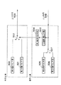
次に、上記各実施例1乃至3を適用した符号化復号化装置を参考例として示す。図5は本発明の参考例の構成を示すブロック図であり、上記第1および第2の実施例の符号化装置と第3の実施例の復号化装置とを組み合わせたものである。図5の符号化側において、500は第1の量子化手段、501は第2の量子化手段、502は量子化手段500、501を切り換えるスイッチ、508は出力符号であり、これら以外の詳細な構成は上記第1および第2の実施例と同じである。復号化側において、503は伝送誤り検出手段、504は誤り頻度判定手段、505は第1の復号化手段、506は第2の復号化手段、507は復号化手段505、506を切り換えるスイッチ、509は復号化側の入力符号であり、これら以外の詳細な構成は上記第3の実施例と同じである。
【0026】
次に、上記参考例の動作について説明する。復号化側の誤り検出手段503は、伝送されてきた入力符号509の伝送誤りを検出する。誤り頻度判定手段504は、検出された伝送誤りの頻度を定められたしきい値と比較し、誤り頻度がしきい値未満であれば、第1の量子化手段500と第2の量子化手段501のうち、量子化誤差が小さい方の量子化手段をスイッチ502により選択し、誤り頻度がしきい値以上であれば、スイッチ502を第1の量子化手段500側に固定する。復号化側の動作は、上記第3の実施例と同じである。
【0027】
伝送誤りの頻度が高くなると、復号化において第2の量子化手段501の第2段階がパスされる割合が増加し、復号した量子化値の精度が低下する。したがって、本参考例のように、誤りの頻度を監視し、頻度が高い場合には、相手の符号化側のスイッチを第1の量子化手段500に固定することにより、復号化側で復号した量子化値の精度の低下を少なくすることができる。また、双方向の伝送路では、復号化側が受信した入力符号509の誤り頻度から、符号化側が送信する出力符号508の相手側受信時の誤り頻度が推定できるので、本参考例のように、復号化側での誤り頻度による自分の符号化側の量子化手段を切り換えスイッチ502の制御を双方で行なえば、付加情報を付け加えることなく、伝送誤りに対する耐性を高めることができる。
【0028】
【発明の効果】
以上のように、本発明は、LSPパラメータを復号化する復号化装置に、フレーム単位で独立にベクトル量子化されたLSPパラメータを復号化して量子化値を得る第1の復号化手段と、前記第1の復号化手段で得られた量子化値と参照フレームの量子化値から求めた予測値を用いてフレーム間の相関を利用してベクトル量子化されたLSPパラメータを復号化する第2の復号化手段とを備えたことにより、入力音声信号の状態に関わらず、安定した高い復号化精度が得られるという効果がある。
【0029】
また、本発明は、隣接フレーム間の相関を利用する復号化動作では、第1の復号化手段で得られた量子化値と参照フレームの量子化値から予測値を求め、この予測値を用いてフレーム間の相関を利用してベクトル量子化されたLSPパラメータを復号化することにより、伝送誤りに対する耐性を高めるという効果がある。
【図面の簡単な説明】
【図1】本発明の第1の実施の形態におけるLSPパラメータ符号化装置の構成を示すブロック図
【図2】本発明の第2の実施の形態の構成として、図1中の第2の量子化手段の詳細を示すブロック図
【図3】本発明の第2の実施の形態の第2の量子化手段における第2段階の処理を示す模式図
【図4】本発明の第3の実施の形態の構成として、第1および第2の実施の形態の符号化装置に対応する復号化装置の構成を示すブロック図
【図5】本発明の参考例として、第1および第2の実施の形態の符号化装置と第3の実施の形態の復号化装置とを組み合わせた符号復号化装置の構成を示すブロック図
【図6】従来例のフレーム間の相関を利用するLSPパラメータ量子化装置の構成を示すブロック図
【符号の説明】
100 LSPパラメータ
101 フレーム単位で独立に量子化を行なう第1の量子化手段
102 隣接フレーム間の相関を利用して量子化を行なう第2の量子化手段
103、104 復号化手段
105 誤差比較手段
106 量子化手段を切り換えるスイッチ
107 入力音声信号
108 算出したLSPパラメータ
109 第1の量子化手段101の出力符号
110 第2の量子化手段102の出力符号
111 第1の量子化手段101による量子化値
112 第2の量子化手段102による量子化値
113 スイッチ106の切り換えを制御する信号
114 出力符号
200 LSPパラメータ算出手段
201 第1段目の誤差最小化手段
202 第1の符号帳
203、207 復号化手段
204 過去の量子化値から現フレームの値を線形に予測する予測手段
205 第2段目の誤差最小化手段
206 第2の符号帳
208 過去の量子化値を蓄えておくバッファ
210 入力音声信号
211 現フレームのLSPパラメータ
212 第1段階の出力符号
213 第1段階の量子化値
214 第2段階の出力符号
215 現フレームの量子化値
216 過去の量子化値
217 予測された現フレームのLSPパラメータ
300 前フレームのLSPパラメータの量子化前の値
301 現フレームのLSPパラメータの量子化前の値
302 前フレームの量子化値
303 現フレームの第1段階の量子化値
304 現フレームの予測値
305 予測値と量子化前の値との誤差
306 現フレームの量子化値
400 伝送誤り検出手段
401 スイッチ制御手段
402 第1の量子化手段による符号ベクトルを格納する符号帳
403 第2の量子化手段の第1段階による符号ベクトルを格納する符号帳
404 第2の量子化手段の第2段階による符号ベクトルを格納する符号帳
405 予測手段
406 復号化手段
407、408 復号化手段を切り換えるスイッチ
409 出力する復号値を切り換えるスイッチ
410 前フレームの量子化値を蓄えるバッファ
412 第1の量子化手段による量子化値
413 第2の量子化手段の第1段階による量子化値
414 現フレームの予測値
415 第2の量子化手段の第2段階による量子化値
416 復号化手段の出力量子化値
500 第1の量子化手段
501 第2の量子化手段
502 量子化手段を切り換えるスイッチ
503 誤り検出手段
504 誤り頻度判定手段
505 第1の復号化手段
506 第2の復号化手段
507 スイッチ
508 符号化側の出力符号
509 復号化側の入力符号
600 LSPパラメータ
601 過去の量子化値を蓄えておくバッファ
602 過去の量子化値から現フレームの値を線形に予測する予測手段
603 予測値と入力値との誤差を最小にする符号を符号帳から選択する誤差最小化手段
604 符号帳
605 出力符号から量子化値を復号する復号化手段
606 入力音声信号
607 現フレームのLSPパラメータ
608 出力符号
609 現フレームの量子化値
610 過去の量子化値
611 予測された現フレームのLSPパラメータ[0001]
TECHNICAL FIELD OF THE INVENTION
The present invention relates to an encoding / decoding device for an LSP parameter, which is a characteristic parameter of spectrum information of an audio signal.
[0002]
[Prior art]
2. Description of the Related Art Conventionally, in an audio encoding device having a bit rate of about 4 to 8 kbqs, a method of analyzing an audio signal to separate and encode spectral information and sound source information is mainly used. The LSP parameter is a characteristic parameter representing spectrum information, and usually requires about ten orders per frame. The most basic method of encoding LSP parameters is a method of quantizing individual values as a scalar. However, since the quantization effect is low, vector quantization for collectively quantizing a plurality of LSP parameters is often used. Used. In addition, since the LSP parameter has a large correlation between adjacent frames, quantization efficiency can be improved by using the correlation between frames.
[0003]
FIG. 6 is a block diagram showing a configuration of a conventional LSP parameter quantization device using correlation between frames, 600 is an LSP parameter calculation means, 601 is a buffer for storing past quantization values, and 602 is a past buffer. Prediction means for linearly predicting the value of the current frame from the quantized value; 603, an error minimizing means for selecting a code for minimizing an error between the predicted value and the input value from a codebook; 604, a codebook; It is a decoding means for decoding a quantized value from a code.
[0004]
The processing in the conventional LSP parameter quantization device configured as described above will be described. The LSP parameter calculation means 600 calculates an
[0005]
[Problems to be solved by the invention]
However, in the above-described conventional apparatus, a high prediction gain is obtained in a state where the input audio signal is almost steady, and high-precision quantization can be performed. Also, the accuracy of quantization is reduced. When the frame length increases, the transient factor between adjacent frames increases, and the inter-frame correlation decreases, so that the prediction gain similarly decreases. Therefore, the quantization method of performing prediction using the correlation between adjacent frames is suitable for a speech coding method with a short frame length while the input speech signal is easily regarded as stationary between adjacent frames, but is suitable for a speech coding method with a short frame length. It was difficult to apply to the encoding method.
[0006]
In addition, since the present value is predicted from the past quantization value, the effect of a code error occurring on the transmission path propagates not only to the error frame but also to the subsequent frames, and thus is susceptible to errors.
[0007]
An object of the present invention is to solve the above-mentioned conventional problem, and to provide an LSP parameter decoding apparatus and a decoding method capable of securing high quantization accuracy and improving error resistance even when an input audio signal is in a transient state. The aim is to provide a method.
[0008]
[Means for Solving the Problems]
In order to achieve the above object, the present invention provides a decoding device for decoding an LSP parameter which is a characteristic parameter of spectrum information of an audio signal, and decodes an LSP parameter which is independently vector-quantized for each frame. A first decoding means for obtaining a quantization value by using a correlation between frames using a quantization value obtained by the first decoding means and a prediction value obtained from a quantization value of a reference frame. And a second decoding means for decoding the LSP parameter which has been vector-quantized.
[0009]
The present invention also relates to a decoding method for decoding an LSP parameter which is a characteristic parameter of spectrum information of an audio signal, wherein a first decoding step for decoding an LSP parameter which is vector-quantized independently in a frame unit. An LSP parameter that is vector-quantized using a correlation between frames using the prediction value and a prediction value from the quantization value obtained in the first decoding step and the quantization value of the reference frame. The LSP parameter is decoded by each processing operation of the second decoding step of decoding
[0010]
[Action]
Therefore, according to the present invention, the first decoding unit that performs decoding independently on a frame basis is used in a portion where the correlation between adjacent frames is small, and the first decoding unit is used in a portion where the correlation between adjacent frames is large. By decoding the vector-quantized LSP parameter using the correlation between frames using the quantization value obtained by the quantization means and the prediction value obtained from the quantization value of the reference frame, the input speech signal is decoded. Regardless of the state, stable high decoding accuracy can be obtained.
[0011]
Further, in the present invention, in a decoding operation using correlation between adjacent frames, a prediction value is obtained from a quantization value obtained by the first decoding unit and a quantization value of a reference frame, and the prediction value is calculated using the prediction value. By decoding the vector-quantized LSP parameters using the correlation between frames, it is possible to increase the resistance to transmission errors.
[0012]
BEST MODE FOR CARRYING OUT THE INVENTION
(Embodiment 1)
Hereinafter, a first embodiment of the present invention will be described with reference to the drawings. FIG. 1 is a block diagram showing a configuration of an LSP parameter encoding apparatus according to a first embodiment of the present invention, wherein 100 is an LSP parameter calculating means, and 101 is a first quantization which performs quantization independently on a frame basis.
[0013]
Next, the operation of the above embodiment will be described. The
[0014]
As described above, according to the present embodiment, the first quantization means 101 which can expect stable quantization accuracy irrespective of the state of the input audio signal, and the high quantization accuracy when the input audio signal is almost stationary. By switching and using the quantization means of the two different quantization methods of the second quantization means 102 which can be expected to obtain high stable quantization accuracy regardless of the state of the input audio signal. .
[0015]
In addition, since the second quantization means 102 performs quantization using the correlation between adjacent frames, the effect of the transmission error propagates to the next and subsequent frames, but the first quantization means 101 , Quantization is performed independently, so that the effects of errors do not propagate. Therefore, the propagation of the influence of the error is limited to the section in which the second quantization means is continuously selected, and does not propagate beyond the frame in which the first quantization means is selected. The probability that the first quantization means and the second quantization means are selected greatly varies depending on the properties of the input speech signal, but is about one-to-one to one-to-two in normal conversation. Is rarely selected continuously over a long interval. Therefore, the propagation of the influence of the error is limited to a short section, and the resistance to the error is higher than that of the conventional example in which the influence of the error continues to propagate.
[0016]
(Embodiment 2)
FIG. 2 is a block diagram showing the configuration of the second embodiment of the present invention, and shows the details of the second quantization means 102 in FIG.
[0017]
Next, the operation of the above embodiment will be described. The LSP parameter calculation means 200 calculates the
[0018]
Here, the second stage processing will be described with reference to FIG. In FIG. 3,
[0019]
The
p n = αq n-1 + (1-α) υ n
Therefore, the
[0020]
By fixing the prediction coefficient α, the error minimization process in the second stage only selects a code vector that minimizes the error with respect to the
[0021]
As described above, according to the present embodiment, the prediction value of the current frame is predicted from the information of the past frame and the information of the current frame. Even if there is an effect, it is possible to reduce the effect worth the predicted value of the current frame, and it is possible to increase the robustness worth the transmission error.
[0022]
(Embodiment 3)
FIG. 4 is a block diagram showing the configuration of the third embodiment of the present invention, and shows the configuration of a decoding device corresponding to the encoding devices of the first and second embodiments. In FIG. 4, 400 is a transmission error detecting means, 401 is a switch control means, 402 is a codebook storing a code vector by the first quantizing means, and 403 is a code vector in the first stage of the second quantizing means. A codebook to be stored, 404 is a codebook to store a code vector in the second stage of the second quantization means, 405 is prediction means, 406 is decoding means, 407 and 408 are switches for switching decoding means, and 409 is A
[0023]
Next, the operation of the above embodiment will be described. If the transmission code is a code by the first quantization means in the encoding apparatus, the
[0024]
As described above, according to the present embodiment, the second stage of the second quantization unit that propagates the influence of the past error is passed after the next frame of the frame in which the error has occurred, so that the influence of the error can be reduced. Can be prevented from propagating after the next frame, and the effect of errors can be minimized.
[0025]
(Reference example)
Next, an encoding / decoding apparatus to which each of the first to third embodiments is applied will be described as a reference example. FIG. 5 is a block diagram showing the configuration of the reference example of the present invention, which is a combination of the encoding devices of the first and second embodiments and the decoding device of the third embodiment. On the encoding side in FIG. 5,
[0026]
Next, the operation of the above reference example will be described. The error detection means 503 on the decoding side detects a transmission error of the transmitted
[0027]
When the frequency of transmission errors increases, the rate at which the second stage of the second quantization means 501 is passed in decoding increases, and the accuracy of the decoded quantization value decreases. Therefore, as in the present reference example, the frequency of errors is monitored, and when the frequency is high, decoding is performed on the decoding side by fixing the switch on the encoding side of the other party to the first quantization means 500. A decrease in precision of the quantization value can be reduced. On the other hand, in the bidirectional transmission path, the error frequency of the
[0028]
【The invention's effect】
As described above, the present invention provides a decoding device that decodes LSP parameters, a first decoding unit that obtains a quantized value by decoding LSP parameters that are vector-quantized independently on a frame-by-frame basis, A second decoding unit that decodes the vector-quantized LSP parameter using the correlation between frames using the quantization value obtained by the first decoding unit and the prediction value obtained from the quantization value of the reference frame; By providing the decoding means, there is an effect that stable and high decoding accuracy can be obtained regardless of the state of the input audio signal.
[0029]
Further, in the present invention, in a decoding operation utilizing correlation between adjacent frames, a prediction value is obtained from a quantization value obtained by the first decoding means and a quantization value of a reference frame, and the prediction value is used. By decoding the vector-quantized LSP parameter using the correlation between the frames, there is an effect of increasing the resistance to transmission errors.
[Brief description of the drawings]
FIG. 1 is a block diagram showing a configuration of an LSP parameter encoding device according to a first embodiment of the present invention; FIG. 2 is a block diagram showing a configuration of an LSP parameter encoding device according to a second embodiment of the present invention; FIG. 3 is a block diagram showing details of the quantization means; FIG. 3 is a schematic diagram showing a second-stage process in the second quantization means according to the second embodiment of the present invention; FIG. 5 is a block diagram showing a configuration of a decoding device corresponding to the encoding devices of the first and second embodiments as a configuration of the embodiment. FIG. 5 is a block diagram showing the first and second embodiments as a reference example of the present invention. FIG. 6 is a block diagram showing a configuration of a code decoding apparatus in which the encoding apparatus of FIG. 1 and the decoding apparatus of the third embodiment are combined. FIG. 6 is a configuration of a conventional LSP parameter quantization apparatus using correlation between frames. [Description of reference numerals]
100 LSP parameter 101 First quantization means 102 for performing quantization independently in frame units Second quantization means 103 and 104 for performing quantization using the correlation between adjacent frames Decoding means 105 Error comparison means 106 Switch 107 for switching quantization means Input audio signal 108 Calculated LSP parameter 109 Output code 110 of first quantization means 101 Output code 111 of second quantization means 102 Quantized value 112 of first quantization means 101 Quantized value 113 by second quantizing means 102 Signal 114 for controlling switching of switch 106 Output code 200 LSP parameter calculating means 201 First-stage error minimizing means 202 First codebook 203, 207 Decoding means 204 Prediction means 2 for linearly predicting the value of the current frame from the past quantized value 05 Second-stage error minimizing means 206 Second codebook 208 Buffer 210 for storing past quantization values Input audio signal 211 LSP parameter 212 of current frame First-stage output code 213 First-stage quantum Quantized value 214 Output code of second stage 215 Quantized value of current frame 216 Past quantized value 217 LSP parameter of predicted current frame 300 Value of LSP parameter of previous frame before quantization 301 LSP parameter of current frame Value before quantization 302 Quantized value of previous frame 303 Quantized value of first stage of current frame 304 Predicted value of current frame 305 Error between predicted value and value before quantization 306 Quantized value of current frame 400 Transmission Error detection means 401 Switch control means 402 Codebook 403 storing code vectors by first quantization means Second Codebook 404 storing the code vector according to the first stage of the quantization means of the above (2) Codebook 405 storing the code vector according to the second step of the second quantization means Prediction means 406 Decoding means 407, 408 Switching between the decoding means Switch 409 Switch for switching the decoded value to be output 410 Buffer 412 for storing the quantization value of the previous frame Quantization value 413 by the first quantization means Quantization value 414 by the first stage of the second quantization means 414 Prediction of the current frame Value 415 Quantized value in second stage of second quantizing means 416 Output quantized value of decoding means 500 First quantizing means 501 Second quantizing means 502 Switch for switching quantization means 503 Error detecting means 504 Error frequency determination means 505 First decoding means 506 Second decoding means 507 Switch 508 Encoding side Output code 509 Decoding-side input code 600 LSP parameter 601 Buffer 602 for storing past quantized values Predicting means 603 for linearly predicting the value of the current frame from past quantized values Error between predicted value and input value Error minimizing means 604 for selecting a code that minimizes from the codebook 604 codebook 605 decoding means 606 for decoding the quantized value from the output code input audio signal 607 LSP parameter 608 of current frame output code 609 quantization of current frame Value 610 Past quantization value 611 Predicted LSP parameter of current frame
Claims (2)
Priority Applications (1)
| Application Number | Priority Date | Filing Date | Title |
|---|---|---|---|
| JP2002110037A JP3557413B2 (en) | 2002-04-12 | 2002-04-12 | LSP parameter decoding apparatus and decoding method |
Applications Claiming Priority (1)
| Application Number | Priority Date | Filing Date | Title |
|---|---|---|---|
| JP2002110037A JP3557413B2 (en) | 2002-04-12 | 2002-04-12 | LSP parameter decoding apparatus and decoding method |
Related Parent Applications (1)
| Application Number | Title | Priority Date | Filing Date |
|---|---|---|---|
| JP25201194A Division JP3557255B2 (en) | 1994-10-18 | 1994-10-18 | LSP parameter decoding apparatus and decoding method |
Publications (2)
| Publication Number | Publication Date |
|---|---|
| JP2002372997A JP2002372997A (en) | 2002-12-26 |
| JP3557413B2 true JP3557413B2 (en) | 2004-08-25 |
Family
ID=19193884
Family Applications (1)
| Application Number | Title | Priority Date | Filing Date |
|---|---|---|---|
| JP2002110037A Expired - Lifetime JP3557413B2 (en) | 2002-04-12 | 2002-04-12 | LSP parameter decoding apparatus and decoding method |
Country Status (1)
| Country | Link |
|---|---|
| JP (1) | JP3557413B2 (en) |
Families Citing this family (1)
| Publication number | Priority date | Publication date | Assignee | Title |
|---|---|---|---|---|
| KR100486732B1 (en) * | 2003-02-19 | 2005-05-03 | 삼성전자주식회사 | Block-constrained TCQ method and method and apparatus for quantizing LSF parameter employing the same in speech coding system |
-
2002
- 2002-04-12 JP JP2002110037A patent/JP3557413B2/en not_active Expired - Lifetime
Also Published As
| Publication number | Publication date |
|---|---|
| JP2002372997A (en) | 2002-12-26 |
Similar Documents
| Publication | Publication Date | Title |
|---|---|---|
| US8909521B2 (en) | Coding method, coding apparatus, coding program, and recording medium therefor | |
| KR100712056B1 (en) | Method and device for robust predictive vector quantization of linear prediction parameters in variable bit rate speech coding | |
| JP3557255B2 (en) | LSP parameter decoding apparatus and decoding method | |
| US9269366B2 (en) | Hybrid instantaneous/differential pitch period coding | |
| EP2127088B1 (en) | Audio quantization | |
| KR20120096541A (en) | Method, system, and apparatus for compression or decompression of digital signals | |
| KR20080092770A (en) | The quantizer and method of lsf coefficient in wide-band speech coder using trellis coded quantization algorithm | |
| US20070143118A1 (en) | Apparatus and method for lossless audio signal compression/decompression through entropy coding | |
| JP3583551B2 (en) | Error compensator | |
| JP3557416B2 (en) | LSP parameter encoding / decoding apparatus and method | |
| EP1202252A2 (en) | Apparatus for bandwidth expansion of speech signals | |
| JP3557413B2 (en) | LSP parameter decoding apparatus and decoding method | |
| JP3557414B2 (en) | LSP parameter encoding apparatus and encoding method | |
| KR100629997B1 (en) | encoding method of audio signal | |
| JP3557415B2 (en) | LSP parameter decoding apparatus and method | |
| CN101156318B (en) | Predictor | |
| JP4091506B2 (en) | Two-stage audio image encoding method, apparatus and program thereof, and recording medium recording the program | |
| JP2655063B2 (en) | Audio coding device | |
| JP3218630B2 (en) | High efficiency coding apparatus and high efficiency code decoding apparatus | |
| JP3602934B2 (en) | Voice information communication system | |
| JPH06118999A (en) | Method for encoding parameter information on speech |
Legal Events
| Date | Code | Title | Description |
|---|---|---|---|
| TRDD | Decision of grant or rejection written | ||
| A01 | Written decision to grant a patent or to grant a registration (utility model) |
Free format text: JAPANESE INTERMEDIATE CODE: A01 Effective date: 20040511 |
|
| A61 | First payment of annual fees (during grant procedure) |
Free format text: JAPANESE INTERMEDIATE CODE: A61 Effective date: 20040517 |
|
| R150 | Certificate of patent or registration of utility model |
Free format text: JAPANESE INTERMEDIATE CODE: R150 |
|
| FPAY | Renewal fee payment (event date is renewal date of database) |
Free format text: PAYMENT UNTIL: 20090521 Year of fee payment: 5 |
|
| FPAY | Renewal fee payment (event date is renewal date of database) |
Free format text: PAYMENT UNTIL: 20100521 Year of fee payment: 6 |
|
| FPAY | Renewal fee payment (event date is renewal date of database) |
Free format text: PAYMENT UNTIL: 20110521 Year of fee payment: 7 |
|
| FPAY | Renewal fee payment (event date is renewal date of database) |
Free format text: PAYMENT UNTIL: 20110521 Year of fee payment: 7 |
|
| FPAY | Renewal fee payment (event date is renewal date of database) |
Free format text: PAYMENT UNTIL: 20120521 Year of fee payment: 8 |
|
| FPAY | Renewal fee payment (event date is renewal date of database) |
Free format text: PAYMENT UNTIL: 20120521 Year of fee payment: 8 |
|
| FPAY | Renewal fee payment (event date is renewal date of database) |
Free format text: PAYMENT UNTIL: 20130521 Year of fee payment: 9 |
|
| FPAY | Renewal fee payment (event date is renewal date of database) |
Free format text: PAYMENT UNTIL: 20130521 Year of fee payment: 9 |
|
| S111 | Request for change of ownership or part of ownership |
Free format text: JAPANESE INTERMEDIATE CODE: R313113 |
|
| S533 | Written request for registration of change of name |
Free format text: JAPANESE INTERMEDIATE CODE: R313533 |
|
| R350 | Written notification of registration of transfer |
Free format text: JAPANESE INTERMEDIATE CODE: R350 |
|
| EXPY | Cancellation because of completion of term |