JP3557217B2 - Storage medium device for storing information data such as video data and / or audio data and information providing device - Google Patents
Storage medium device for storing information data such as video data and / or audio data and information providing device Download PDFInfo
- Publication number
- JP3557217B2 JP3557217B2 JP52895396A JP52895396A JP3557217B2 JP 3557217 B2 JP3557217 B2 JP 3557217B2 JP 52895396 A JP52895396 A JP 52895396A JP 52895396 A JP52895396 A JP 52895396A JP 3557217 B2 JP3557217 B2 JP 3557217B2
- Authority
- JP
- Japan
- Prior art keywords
- data
- storage medium
- information
- atm
- video
- Prior art date
- Legal status (The legal status is an assumption and is not a legal conclusion. Google has not performed a legal analysis and makes no representation as to the accuracy of the status listed.)
- Expired - Fee Related
Links
Images


Classifications
-
- H—ELECTRICITY
- H04—ELECTRIC COMMUNICATION TECHNIQUE
- H04N—PICTORIAL COMMUNICATION, e.g. TELEVISION
- H04N21/00—Selective content distribution, e.g. interactive television or video on demand [VOD]
- H04N21/20—Servers specifically adapted for the distribution of content, e.g. VOD servers; Operations thereof
- H04N21/23—Processing of content or additional data; Elementary server operations; Server middleware
-
- H—ELECTRICITY
- H04—ELECTRIC COMMUNICATION TECHNIQUE
- H04N—PICTORIAL COMMUNICATION, e.g. TELEVISION
- H04N7/00—Television systems
- H04N7/16—Analogue secrecy systems; Analogue subscription systems
- H04N7/173—Analogue secrecy systems; Analogue subscription systems with two-way working, e.g. subscriber sending a programme selection signal
- H04N7/17309—Transmission or handling of upstream communications
- H04N7/17336—Handling of requests in head-ends
Abstract
Description
背景技術
従来のケーブルTVシステムでは、ビデオデータを、配信事業者からケーブルを介して多くの視聴者のモニタ受像機に供給する。近年、多くの番組が各ケーブルTV事業者から多チャンネルを介して配信されているが、ユーザ又は視聴者は、見たい番組が始まり、選局したチャンネルを介して伝送されてくるまで待たなくてはならない。
また、近年、対話型ビデオシステムが提案されている。このような対話型ビデオシステムにおいて、視聴者は、モニタ受像機に表示した映画を選択することができる。このようなビデオオンディマンドシステムでは、ユーザのモニタ受像機や端末装置への直接的な接続が確立され、その後、エンドユーザは、要求した映画を見ることができる。
この周知のシステムでは、例えば、配信事業者の所でシステムが構築された後に、システムを拡張することは、事実上不可能である。このようなシステムにおいて会員数が増え、要求されるビデオの数が増加した場合、新たな対話型ビデオシステムを構築しなければならない。
発明の開示
本発明に係る記憶媒体装置は、情報データを記憶する記憶手段と、ルーティング情報と情報データの関係を示すデータを記憶するテーブル手段と、当該記憶媒体装置の動作を制御するプログラムデータを記憶するメモリ手段と、プログラムデータに基づいて、記憶手段、テーブル手段及びメモリ手段を制御する制御手段と、情報データを、ルーティング情報とともにパケット形式でルーティング手段に送信する少なくとも1つのインターフェースとを備える。情報データは、ビデオ及び/又はオーディオデータであり、ルーティング情報は、インターフェースの仮想チャンネル情報を含み、選択された動作モードを制御する制御データがインターフェースを介して当該記憶媒体装置に受信され、制御手段は、受信された制御データに基づいて、インターフェースの仮想チャンネルを切り換えることにより、情報データが選択された動作モードで再生されるように記憶手段を制御する。
本発明に係る記憶媒体装置は、システムに1以上の記憶媒体装置を追加して接続することにより、システムを拡張することができる。情報データ及びルーティング情報のインターフェースとして、1以上のパケット形式を標準とすることにより、本発明に係る記憶媒体装置の記憶手段を、1以上のハードディスク、1以上の光磁気ディスク、ビデオテープ及び/又はその他の媒体等のいかなる種類の記憶媒体とすることができる。
プログラムデータは、例えば、対話型システムからダウンロードされ、これにより、最低限のソフトウェアのみが記憶媒体装置に記憶される。
情報データは、例えば、ビデオデータ及び/又はオーディオデータからなるが、本発明はこの用途に限定されるものではない。また、本発明に係る記憶媒体装置は、ビデオゲーム、ライブラリ機能及びデータバンクの用途として用いることができるが、最も適した用途の分野は、ビデオオンディマンドサービスである。
インターフェースは、例えば、ATMインターフェースである。ATM(非同期転送モード)の原理及び規格については、1993年3月に国際電気通信連合によって発行された勧告I.150及びI.327に記載されている。ATMは、一般的に、非同期時分割多重化技術を用いた専用パケット型転送モード(a specific packet−oriented transfer mode)に用いられる。多重化された情報のフローは、セルと呼ばれる固体サイズのブロックに組み込まれる。1つのセルは、情報領域とヘッダとにより構成される。ヘッダの主たる機能は、非同期時分割多重内の同一の仮想チャンネルに属するセルを識別することである。
本発明に係る記憶媒体装置は、例えば、ビデオカセットレコーダ(VCR)におけるように、静止画モード動作、早送り再生モード動作、リバース再生モード動作、モザイクモード動作を行う。
さらに、本発明に係る情報提供装置は、1以上の記憶媒体装置と、1以上の端末装置と、記憶媒体装置を端末装置に接続する少なくとも1つのATMスイッチとを備える。記憶媒体装置は、情報データを記憶する記憶手段と、ルーティング情報と上記情報データの関係を示すデータを記憶するテーブル手段と、記憶媒体装置の動作を制御するプログラムデータを記憶するメモリ手段と、プログラムデータに基づいて、記憶手段、テーブル手段及びメモリ手段を制御し、制御信号を端末装置に出力する制御手段と、情報データを、ルーティング情報及び制御信号とともに1以上のATMパケット形式でATMスイッチに送信し、ATMスイッチからATMパケット形式で記憶媒体装置の動作のためのプログラムデータを受信するATMインターフェースとを備える。情報データは、ビデオ及び/又はオーディオデータであり、ルーティング情報は、ATMインターフェースの仮想チャンネル情報を含み、選択された動作モードを制御する制御データがATMインターフェースを介して記憶媒体装置に受信され、制御手段は、受信された制御データに基づいて、ATMインターフェースの仮想チャンネルを切り換えることにより、情報データが選択された動作モードで再生されるように記憶手段を制御する。
本発明のさらなる詳細、特徴、利点については、本発明の実施例を示す図面を参照して以下に説明する。
【図面の簡単な説明】
図1は、インフォメーションオンディマンドのためのシステム全体の構成を示す図である。
図2は、記憶媒体装置の第1の具体的な構成を示す図である。
図3は、記憶媒体装置の第2の具体的な構成を示す図である。
図4は、図2及び図3に示す記憶媒体装置における制御フロー及びデータフローを示す概略図である。
図5は、記憶媒体装置の第3の具体的な構成を示す図である。
図6は、図2に示す記憶媒体装置に相当する記憶媒体装置を、それより得られるデータグループとともに示す図である。
図7は、記憶媒体装置におけるATMインターフェースのタイミングを示す図である。
図8は、図1に示すナビゲーションシステムの具体的な構成を示す図である。
図9は、図1に示すエンドユーザ装置の具体的な構成を示す図である。
図10は、図1に示すシステム管理装置の具体的な構成を示す図である。
図11は、スタガ記録に対する基本的な再生機能を示す図である。
図12は、モザイクメニュー機能を示す図である。
図13、14、14Aは、それぞれ、光磁気ディスクの記録トラックの記録フォーマットを示す図である。
図15は、図14のスタガフォーマットで記録されたデータの再生を示す図である。
図16は、マルチキャスティングの例を示す図である。
図17は、本発明に係るシステムにおける一連の通信工程の例を示す図である。
図18は、本発明に係るシステムの好ましい実施例における一連の通信工程の他の例を示す図である。
発明を実施するための最良の形態
図面を参照した以下の記述では、ハードウェアとソフトウェアの組合せについて説明している。ハードウェアの構成要素の中には、単一の構成要素に組み合わされて、CPUのような機能を時分割多重によって実行するものもある。また、論理(ソフトウェア)ユニット間の接続は、実際には、図に概略的に示したものよりも複雑である。
図1は、本発明に係る対話型通信システムの好ましい実施例における全体の構成を示す図である。このシステムは、ATMスイッチ1(例えば、米国ペンシルバニア州ワレンデイルのフォアシステムインク社製のフォアランナ(商標)ASX−200(Fore SystemsInc.,Warrendale,Pennsylvania,USAのForeRunnerTMASX−200))と、記憶媒体装置20(SMU)と、端末装置40と、システム管理装置60と、ナビゲーション装置30とを備えている。ATMスイッチ1は、仮想チャンネル接続を用いて、記憶装置20と、端末装置40と、システム管理装置60と、ナビゲーション装置30とを互いに選択的に接続し、これらの構成要素間を、データが、ルーティング情報を含む5バイトのセルヘッダと48バイトの情報領域からなるATMパケットの形式で、各装置とATMスイッチ1間に設けられたATMユーザ/ネットワークインターフェースを介して転送される。ATMスイッチ1は、仮想チャンネル識別子等のルーティング情報の変換テーブルを有しており、転送されてくる各ATMパケットのルーティング情報を、出力仮想チャンネルを指定するルーティング情報に変換することによって、ATMパケットを正しい転送先に転送することができる。ATMスイッチは周知のものであり、詳細な説明は省略する。
対話型通信システムについて、特にビデオオンディマンド(VOD)サービスをユーザに提供する具体例を参照して以下に説明する。なお、テレショッピング、ゲーム、その他の情報交換等の用途についても同様に行うことができる。このようなサービスは、一般的にインフォメーションオンディマンドサービスと称される。
図1に示す対話型通信システムにおいて、ビデオ信号及び/又はオーディオ信号は、SMU20に記憶されている。SMU20の幾つかの具体例については、後に詳細に説明する。
図1において、端末装置40はセットップボックスであり、各セットトップボックスは、ナビゲーション装置30やシステム管理装置60と通信を行うことができ、SMU20からのビデオデータ及び/又はオーディオデータ(例えば、MPEG−2規格に準拠して圧縮されている)をデコードし、デコードされたビデオ信号及び/又はオーディオ信号をモニタ受像機43及び/又はスピーカシステム42に供給する。各セットトップボックス又は端末装置40には、例えばキーボートや遠隔操作装置等の入力装置44が接続されている。セットトップボックスは、例えば、モニタ受像機43に表示するためのグラフィックデータを生成してユーザとの対話を容易にするグラフィックプロセッサユニット49を備えている。また、グラフィックプロセッサユニット49に対するデータは、ATMパケットとしてシステム管理装置60から供給される。視聴者は、キーボード44や他の適した入力装置を用いて、セットトップボックス40にインストラクションを入力できるようになっている。セットトップボックス40の具体例については、後に詳細に説明する。
ナビゲーション装置30は、セットトップボックス40のうちのいずれか1つに、提供可能なビデオ番組の情報を供給するようになっている。このような情報は、図形又は文書、又はその組合せによって、セットトップボックス40に接続されたのモニタ受像機43に表示される。提供可能なビデオ番組は、視聴者が選択することができるビデオ番組である。このようなユーザが要求することができる情報を、以下、サービス項目と称する。ナビゲーション装置30の具体例については、後に詳細に説明する。
システム管理装置60は、ATMスイッチ1の動作を管理することによって、対話型通信システム全体の動作を管理する。システム管理装置60の具体例については、後に詳細に説明する。
本発明の好ましい実施例に係る対話型通信システムの主たる特徴は、使用するハードウェアやインストールされるオペレーティングシステムに限定がないことである。各通信動作は、それらの動作専用の制御ソフトウェアプログラムを受信機及び/又は送信機に送ることによって行われるので、受信機及び/又は送信機は、この制御ソフトウェアプログラムをダウンロードした後、受信及び/又は送信を最適に実行することができる。
図1の実施例では、SMU20のうち少なくとも1つは、保管用SMUである。本実施例では、その他のSMU20は、配信用SMUである。保管用SMUは、種々の制御ソフトウェアプログラムやビデオデータ及び/又はオーディオデータを記憶している。保管用SMUは、例えばテープや光磁気ディスクを記憶手段として備え、一方、配信用SMUは、例えば記憶手段として動作の速いハードディスクや光磁気ディスクを備える。光磁気ディスクは、ハードディスクよりも動作が遅いが、テープよりは動作が速い。各配信用SMUは、保管用SMUに記憶されているデータの異なる一部をそれぞれ記憶する。保管用SMUを、配信用SMUとして使用することもできるが、配信用SMUは、VODサービスに用いられる。システム管理装置60は、制御ソフトウェアプログラムを保管用SMUにダウンロードし、保管用SMUは、ビデオオンディマンドサービスの開始時又はその以前に、複数の配信用SMUのうちの1つに対する制御ソフトウェアプログラムのコピー動作を実行する。保管用SMUによる制御ソフトウェアプログラムの配信用SMUへのインストールについては、図18に詳細に示す。配信用SMUは、システム管理装置60からの、具体的には記憶媒体マネージャ62からのコピー動作命令に従って、保管用SMUから供給される必要なビデオデータを記憶する。
システム管理装置60は、端末装置40からのディマンドデータを受信すると、受信したディマンドデータから得られる選択されたビデオデータのための仮想チャンネルや端末装置40のアドレス情報を含む配信制御データを、ATMスイッチ1に出力する。次に、配信用SMUは、選択されたビデオデータを、この端末装置40のためのルーティング情報とともに出力する。ビデオデータのコピー動作が実行される前に、書込動作のためのソフトウェアプログラムが、システム管理装置60からSMU20のRAM24にダウンロードされる。SMU20のCPU22は、RAM24に記憶された書込動作ソフトウェアプログラムに基づいて、物理的記憶媒体21の書込動作を制御する。そして、ビデオサービスが開始する前に、RAM24内の書込動作ソフトウェアプログラムは、システム管理装置60からダウンロードされた読出動作のためのソフトウェアプログラムに置き換えられる。CPU22は、ビデオサービスにおける読出動作ソフトウェアプログラムに基づいて、物理的記憶媒体21の読出動作を制御する。
対話型通信システムは、例えば複数の(配信用)SMUを備える。このシステムにおいて、特定のビデオ及び/又はオーディオ番組を選択する可能性のある端末装置40の数が所定数より少ない場合、その特定のビデオ及び/又はオーディオ番組に必要なビデオデータ及び/又はオーディオデータは、保管用SMUから1つの配信用SMUのみにコピーされる。一方、所定数より多い端末装置が特定のビデオ及び/又はオーディオ番組を選択する可能性がある場合、必要なビデオデータ及び/又はオーディオデータは、保管用SMUから又は上記配信用SMUから、1つ以上の配信用SMUにコピーされる。ここでの所定数は、ある時間における特定のビデオ及び/又はオーディオ番組を要求する端末装置40の数の統計値や実時間監視に基づいて、決定することができる。
本発明の好ましい実施例では、エンドユーザ数を動作中に監視することが可能であり、システムのオーバーロードを防止するためにその構成を大幅に変更することができる。エンドユーザ数が増加した場合、新たな配信用SMUは、保管用SMU又は他の配信用SMUからビデオデータ及び/又はオーディオデータをロードする。
システム管理装置60は、例えば、配信用SMUのうちのいずれかが機能しなくなったときに、バックアップ制御データを出力する。そして、選択されたビデオデータ及び/又はオーディオデータは、バックアップ制御データに基づいて選択された正常に動作している他の配信用SMUから出力される。ATMスイッチ1に設けられている仮想チャンネルの変換テーブルは、システム管理装置60によって更新され、機能していない可能性がある配信用SMUの入力仮想チャンネルが、他の配信用SMUの仮想チャンネルに変更され、変更されたSMUから同じビデオデータ及び/又はオーディオデータが配信される。
ユーザは、所望のナビゲーションサービスを選択し、この所望のナビゲーションサービスを提供するナビゲーション装置30に端末装置40を接続する。サービス項目メニューを表示するソフトウェアプログラムを含むナビゲーションデータと各サービス項目に対応する識別データは、例えば、端末装置40によって選択された少なくとも1つのナビゲーション装置30から予めダウンロードされる。端末装置40に接続されたモニタ受像機43は、利用可能なサービス項目のメニューや、必要に応じてそれに対応する識別データを表示する。ナビゲーション装置30からのメニューは、図形、文書、それらの組合せのいずれかの形式のビデオ情報及び/又はオーディオ情報と制御データとからなり、エンドユーザは、メニューを容易に選択することができる。
ユーザが、入力装置44を介して、モニタ受像機43に表示されているメニューから所望のビデオ番組をポインタで指示したり、又は所望の番組に対応する識別データがモニタ受像機43に表示されているときはそれを入力することによって、ビデオ及び/又はオーディオ番組を選択すると、端末装置40は、識別データをATMスイッチ1を介してシステム管理装置60に供給する。システム管理装置60が公衆ATMネットワークに接続されている場合、このような識別データは、例えば公衆アドレスであってもよい。ナビゲーションデータに、更にSMU20又はナビゲーション装置30から得られるビデオデータを含ませるようにしてもよい。また、ナビゲーション装置30からダウンロードされるナビゲーションデータに、他の選択可能なナビゲーション装置30の情報を含ませるようにしてもよい。
他の実施例において、図示しないが、端末装置40を、公衆ATMスイッチを介してナビゲーション装置に接続することができ、この場合、このようなナビゲーション装置は、公衆アドレスによって選択される。このような公衆ナビゲーション装置を介して、例えば第1の公衆ナビゲーション装置を介して他のナビゲーション装置を選択できるようにしてもよい。
システム管理装置60は、セットトップボックス40から識別データを受信した後、選択されたビデオ番組に対応する端末装置40用のVODソフトウェアプログラムを、端末装置40にダウンロードする。また、システム管理装置60は、VODサービスを開始する前に、選択されたビデオ番組に対応するSMU20用のVODソフトウェアプログラムを、ATMスイッチ1を介してSMU20にダウンロードする。システム管理装置60は、SMU20と、SMU20におけるビデオ番組の位置を示す例えばテーブル形式のデータに応じた最も適切なサービス項目とを選択して、チャンネル情報や選択されたビデオ番組に対応するルーティング情報を含む配信制御データをSMU20に供給し、SMU20は、選択されたビデオ番組を再生する。
SMU20内のコントロール26は、物理的記憶媒体21を制御し、物理的記憶媒体21は、詳細を後述するように、選択されたビデオデータを、端末装置40によって選択された再生モードで再生する。再生されたビデオデータ及び/又はオーディオデータは、ATMインターフェース29に供給せれる。
物理的記憶媒体は、上述のように、ビデオ映画が記録されるハードディスク、光磁気ディスク、テープのいずれであってもよい。
ATMインターフェース29は、例えば、それぞれ48バイトを有する各セルに分割された再生ビデオデータ及び/又はオーディオデータを、SMU20のメモリに記憶されているルーティング情報と結合してATMパケット形式で、ATMスイッチ1に出力する。
端末装置40用の制御情報等のコントローラ26からの制御データは、ATMインターフェース29及びATMスイッチ1を介して端末装置40に供給する。必要とされる再生モード等の端末装置40からの制御データは、ATMスイッチ1及びATMインターフェース29を介して受信される。
ATMスイッチ1は、ATMパケットに付加されたルーティング情報に応じて、端末装置40、SMU20及びシステム管理装置60間のATMパケットのルーティングを行う。私設ATMスイッチ1の変換テーブルは、システム管理装置60によって更新される。
公衆ATMスイッチが私設ATMスイッチと組み合わせて用いられる図示しない実施例では、公衆ATMスイッチの仮想チャンネル接続は、サービスの開始時に公衆アドレスを用いて確立される。
VOD動作は、端末装置40は、ユーザが入力装置44により選択したノーマル再生モード、早送り再生モード、リバース再生モード、早送りリバース再生モード、静止画モード又はその他のモード等の再生モードを要求する制御データを、ATMインターフェース41を介してATMスイッチ1に出力する。そして、ATMスイッチ1は、システム管理装置60に対して制御データのルーティングを行う。システム管理装置60は、選択された再生モードを要求する制御データを、ATMインターフェースを介してATMスイッチ1に出力する。SMU20は、選択されたビデオデータを選択された再生モードで再生する。また、他の変形例として、再生モードを要求する制御データを、端末装置40から直接SMU20にルーティングすることもできる。
VCR動作の場合、物理的記憶媒体は、例えば、上述した他の物理的記憶媒体よりも動作が速いハードディスクである。また、光磁気ディスクを用いることもできるが、この場合、後述するスタガ形式で情報が記録されている。
システム管理装置60は、機能的には、1つ以上の記憶媒体マネージャ62と、1つ以上のサービス項目グループ64及び1以上のサービス項目プロバイダ65を有する記憶媒体グループ63と、サービスルーティングマネージャ66と、プログラムマネージャ67とを備えている。各記憶媒体マネージャ62は、例えば、それが制御する各SMU20に対する静的データ及び/又は動的データを有している。静的データは、例えば、各SMU20の種類、コスト、記録容量からなる。動的データは、例えば、そのSMUがビデオデータ及び/又はオーディオデータにより占有されているか否か、使用中であるか否か、機能しているか否か等のステータス情報を含む。
記憶媒体データ63は、端末装置40からの要求に基づいて、SMU20の割当ての要求を記憶媒体マネージャ62に出力する。このような要求は、一定の時間内又はビデオ番組の全体の時間内にサービスを要求する可能性がある端末装置40の潜在的な数等の統計的な情報によって特定される。他の可能な要求は、例えば、いずれかの端末装置40が、上述したような早送り再生や早送りリバース再生等のより複雑な再生モードを選択する可能性があるか否かである。記憶媒体マネージャ62は、例えばテーブル手段として記憶している各SMU20に対する静的データ及び/又は動的データと、記憶媒体グループ63からの要求とに基づいて、端末装置40に対するビデオサービスのための適切なSMU20又はSMU20内の適切な記憶媒体を記憶媒体グループ63に提示する。さらに、記憶媒体グループ63は、端末装置40のうちの1つの端末装置からの要求に応じて、この端末装置40に対するソフトウェアプログラムのダウンロード動作を制御する。
複数の記憶媒体マネージャ62を用いる場合、各記憶媒体マネージャ62は、ビデオサービスのために、各記憶媒体マネージャ62に属する適切なSMU20を記憶媒体グループ63に提示する。1つの記憶媒体マネージャ62は、記憶媒体グループ63の要求を満足させられない場合、記憶媒体グループ63によって要求された適切なSMU20を提示するように他の記憶媒体マネージャ62に依頼する。具体的には、サービス項目プロバイダ64は、SMU20のうちの1つを割り当てるように、サービス項目グループ65を介して記憶媒体マネージャ62に要求する。また、サービス項目グループ65は、プログラムマネージャ67から始めに供給される制御ソフトウェアプログラムのダウンロード動作を制御する。プログラムマネージャ67は、システム内で使用される全てのソフトウェアプログラムを管理し、更新された適切で有効なプログラムを各装置に供給する。
サービス項目グループ65は、例えば、サービス項目識別子とサービス項目プロバイダとの関係を示す内部のテーブルに基づいて、適切なダウンロード可能なソフトウェアプログラムをセットトップボックスにダウンロードする。サービス項目グループ65は、例えば、サービス項目プロバイダから要求が供給されると、サービス項目グループ内のテーブルに基づいて、どのダウンロード可能ソフトウェアがセットトップボックスの次動作に適切であるかを決定する。
記憶媒体マネージャ62が機能していない場合でも、再生されたビデオデータ及び/又はオーディオデータは、記憶媒体マネージャ62によるルーティングなしに直接ATMスイッチ1に出力されるので、SMU20がビデオデータ及び/又はオーディオデータを出力している間に、機能していない記憶媒体マネージャ62を復帰させることができる。
次に、フルVCR機能、例えば早送り再生モード、リバース再生モード、早送りリバース再生モード、静止画モードについて説明する。フルVCR機能では、例えばハードディスクのような高速の記憶媒体が用いられる。この高速の記憶媒体は、SMUのうちの1つ以上のSMUに設置されている。ビデオオンディマンドサービスの開始時において、選択されたビデオ番組又は端末装置40からのVCR機能の可能性があるビデオ番組のビデオデータ及び/又はオーディオデータは、保管用SMU又は1つの配信用SMUから、この高速の記憶媒体にコピーされる。高速の記憶媒体は、システム管理装置60によって制御され、セットトップボックス40によって要求された再生モードでビデオデータ及び/又はオーディオデータを出力する。システム管理装置60は、エンドユーザによってフルVCR機能が要求されたときは、仮想チャンネルを変更し、このようなエンドユーザは、変更された仮想チャンネルを介してフルVCR機能が可能なハードディスクを備えたSMUに接続される。スタガ形式で情報が記録された光磁気ディスクからの情報が端末装置40に供給され、その端末装置が、例えば早送り再生モード又は早送りリバース再生モードを要求した場合、高速のハードディスクを備えた別のSMUが用いられる。これは、要求から、この再生モードで配信する他の仮想チャンネルが使用可能となるまでに時間がかかっても構わない場合には、有用である。高速のハードディスクを直ちに用いることができる時には、要求された時に使用されているバーチャルチャンネルのタイムポインタに一致したタイムポインタで高速のハードディスクを用いることができ、またそのハードディスクをスピードアップしたり、スローダウンでき、当然、高速のハードディスクのタイムポインタ及びスピードと、フォワード又はリバーススタガ形式で記録された情報を含む光磁気ディスクから選択された再生モードで情報を配信する他のバーチャルチャンネルのタイムポインタ及びスピードとが一致したときに、ハードディスクの使用を終了することができる。
セットトップボックス40が、早送りモード又は早送りリバースモードのような単純なVCR機能を要求したときは、これらの単純なVCR機能は、他の配信用SMU20によって行うことができる。この場合、高速の記憶媒体を備えていない配信用SMUは、例えば、ATMインターフェースを介する多数の仮想チャンネルにおいてそれぞれ異なる遅延時間を有するように後述するフォーマットで記録されたビデオデータ及び/又はオーディオデータを出力する。そして、ATMスイッチ1は、システム管理装置60の制御の下に、入力仮想チャンネルと出力仮想チャンネルとの関係を変更して、ビデオデータ及び/又はオーディオデータを、要求された再生モードでセットトップボックス40に供給する。
ここで、図1に示すテーブルデータを用いて端末装置40、システム管理装置60及びSMU20間に確立される通信の具体例について、説明する。端末装置40(STB−2)が、映画に対応した識別番号678901を指示して選択する映画を要求し、識別番号678901が、ナビゲーション装置30のうちの1つから時刻0:09に供給されると、サービス項目プロバイダ64(SIP−1)のうちの1つが、この識別番号によって指定される。
そして、サービス項目プロバイダ64(SIP−1)は、現在の時刻を確認し、内部のテーブルから、映画の開始時刻として次の配信可能なタイムポイント0:10と、映画のビデオデータ及び/又はオーディオデータを記憶しているSMU20を指定する番号「2」及び、タイムポイント0:10において映画を頭から配信することができるSMU20からのサービス項目ストリーム(SIS)のうちの1つを指定する番号「2」を含む配信制御データと、このストリームの仮想チャンネル番号「21」とを得て、端末番号「2」によって指定されるSMU20に、SIS番号「2」と、仮想チャンネル番号「21」と、端末装置番号「STB−2」とを供給する。
サービス項目プロバイダ64(SIP−1)は、サービス項目プロバイダ64(SIP−1)内で利用可能な他のテーブルデータに基づいて、ATMスイッチ1内の変換テーブルを更新し、サービス項目ストリーム(SIS)に対する入力仮想チャンネル番号「21」と、端末装置40(STB−2)に対する出力仮想チャンネル番号「21」との関係を確立する。したがって、要求された映画のデータストリームは、時刻0:10において、映画の頭から端末装置40(STB−2)に供給される。
端末装置40(STB−2)が、フルVCR機能のためにサービス項目プロバイダ64(SIP−1)のうちの1つを要求すると、そのサービス項目プロバイダ64(SIP−1)は、内部のテーブルから、フルVCR機能を有するSMU20を指定する番号「4」及びこの番号「4」によって指定されたSMU20からのサービス項目ストリーム(SIS)のうちの1つを指定する番号「1」を含む配信制御データを、仮想チャンネル番号「28」及び端末装置番号「STB−1」とともに得る。
サービス項目プロバイダ64(SIP−1)は、サービス項目プロバイダ64(SIP−1)内で利用可能な他のテーブルデータに基づいて、ATMスイッチ1内の変換テーブルを更新し、サービス項目ストリーム(SIS)に対する入力仮想チャンネル番号「28」と、端末装置40(STB−1)に対する出力仮想チャンネル番号「7」との関係を確立する。したがって、要求された映画のデータストリームは、フルVCR機能を要求した端末装置40(STB−1)に供給される。
上述したような対話型通信システムは、多くのサーバオーナ、ナビゲーション装置オーナ、システム管理装置オーナ及びユーザからなるシステムのプラットホームとして用いるのに適している。この場合、1つのパーティは、例えば、システム管理装置60、及び/又は、1又は複数のナビゲーション装置30と同様に、1又は複数のSMU20を利用することができる。
図1において、システム全体は、単一のATMスイッチ1を中心として構成されている。2つ以上の私設ATMスイッチ及び/又は公衆ATMスイッチからなるシステムも、同様に構成することができる。さらに、他の種類の伝送ネットワークを用いることもできる。しかしながら、1以上のATMスイッチを用いたネットワークは、将来性がある最も適したネットワークの構成であると考えられる。
次に、各装置について詳細に説明する。
図2は、SMU20の構成を示す図である。各SMU20は、例えば光磁気(MO)ディスク及びそれに対応するドライバ又は1以上のハードディスク及びそれに対応するドライバからなる物理的記憶媒体21と、SMU20の一部としての又はその外部に設けられたATMインターフェース29と、例えばテーブルを記憶するメモリ25と、CPU22、RAM24、ROM23及びバス27からなるコントローラ26とを備える。
コントローラ26のCPU22は、ROM23に記憶されているソフトウェアプログラム、RAM24に追加されてダウンロードされた制御ソフトウェアプログラム及びSMU20のメモリ25に記憶されているテーブルデータに基づいて、物理的記憶媒体21とSMU20の他部分の動作を制御する。
物理的記憶媒体21は、主としてサービス項目を含んでいるが、端末装置40又は1以上のSMU20に必要に応じてダウンロードされる制御ソフトウェアプログラムも含んでいる。
SMU20のROM23は、例えば、マイクロカーネルオペレーティングシステムと、ATMドライバ、光磁気ディスクドライバ等の記憶媒体インターフェースレジデントソフトウェアとを記憶している。マイクロカーネルオペレーティングシステムは、例えばSMU20によって後で実行される通信のために特別に作成された制御ソフトウェアのダウンロード等の最も初歩的な通信動作のみを行うことを可能にする基本命令セットとして機能する。ATMドライバは、ATMインターフェース29を介する通信を確立するのに用いられる。光磁気ディスクドライバは、物理的記憶媒体21が機能する後述のモードを決定する。また、コントローラ26は、仮想チャンネルと端末装置40との関係を確立するためのテーブル25を有している。
ATMインターフェース29は、例えば、全二重モードでATMスイッチ1と通信を行い、この場合、ATMインターフェース29は、出力ATMパケット28と入力ATMパケット28を同時に送受する。このようなATMパケット28は、図2に示すように、通常5バイトからなるヘッダ部Aと、通常48バイトからなる情報領域部Bとを有する。
RAM24は、ROM23内の実行可能なコードと、サーバを最適に機能させるためのダウンロード可能なモジュールと、バッファとを有している。
図3は、SMU20の他の構成を示す図である。この図3において、バス27は、高いスループットを得るために、独立した制御バスと、独立したデータバスとに分割されている。
図4は、図3に示したSMU20における制御のフロー及びデータのフローを概略的に示したものである。ここでは、入出ビデオデータ及び/又はオーディオデータと、入出制御データと、ダウンロードされる入力制御ソフトウェアプログラムとを区別している。ビデオデータ及び/又はオーディオデータ、制御データ、ソフトウェアプログラムの各パケットは、同じSMU20又は同じ端末装置40に転送されるとしても、互いに区別することができるように、ヘッダに異なるルーティング情報を有している。
図5は、SMU20の第3の構成を示す図であり、ATMスイッチ1と、SMU20のATMインターフェース29とが一体化されている。この結果、SMU20から直接ATMインターフェース41を介する端末装置40への接続を確立することができる。この場合、システム管理装置60は、ATMスイッチ1に接続され、又はコントローラ26がシステム管理装置60の機能を行うようにしてもよい。
図6は、図2の実施例に対応したSMU20を示し、例えばディスク等の物理的記憶媒体からデータセグメントを読み出して、出力する方法を示している。例えば、データグループは、3つの仮想チャンネルを介して出力される。これらのチャンネルは、独立した物理チャンネルとしてもよい。この図は、スタガ記録データの再生の原理を示すが、これについては後に詳細に説明する。ここに示すSMU20は、バッファ210と、タイマ211とを備え、バッファ210は、例えばATMインターフェース29の一部である。ビデオデータは、所定数Tのセンテンスに分割され、ここで、Tはチャンネル数に対応するものであり、図6の場合は3である。各センテンスは、所定数Nのデータグループに分割され、Nは、図6の場合は4である。図6の左上部に示すように、データグループの順番が、例えば1番目のセンテンスのn番目(n=1、2、3、4、・・・N)のデータグループの後にT番目、T−1番目、・・・T−(T−2)番目のセンテンスのn番目のデータグループが順に続き、nを増加しながらこの操作を繰り返して得られる順序に変えられた後に、ビデオデータは、物理的記憶媒体21に記録される。
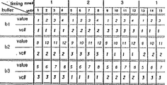
上述のようにして記録されたビデオデータは、物理的記憶媒体21から順次、繰り返し再生される。T個の各センテンスのn番目のデータグループは、バッファ210に順次記憶され、AMTインターフェース29を介してそれぞれ異なる仮想チャンネルに出力される。T個のセンテンスの各N個のデータグループが出力された後、仮想チャンネルは、図7に示すように、次のサイクル及びそれに続くサイクルに切り換えられ、図6の右側に示すように、N×T個のデータグループが、互いに1センテンスの時間差を有して各仮想チャンネルを介し、連続的に再生される。
図8は、ナビゲーション装置30の構成を示す図である。ナビゲーション装置30は、例えば、CPU32、ROM33、端末装置40にダウンロードされるナビゲーションソフトウェアプログラムを記憶するRAM34、バス37及び配信可能なビデオ番組、例えば配信能なビデオ番組の公衆アドレス等の識別データのためのテーブル35からなるコントローラ36と、ATMインターフェース31とを備える。コントローラ36は、ROM33及びRAM34に記憶されているプログラムに基づいて、ナビゲーション装置30の動作を制御する。セットトップボックス40がナビゲーション装置30にナビゲーション動作を要求すると、ナビゲーション装置30は、ナビゲーションソフトウェアプログラムをセットトップボックス40にダウンロードする。そして、ナビゲーション装置30は、提供可能なビデオ番組とその識別データに関する情報を、セットトップボックス40に供給する。公衆ネットワークを対話型通信システムに用いるときは、公衆アドレスを使用することができる。対話型通信システムが複数のナビゲーション装置30を有し、これらのナビゲーション装置が例えば日本語バージョン、英語バージョン、三次元グラフィックバージョン等を取り扱う場合、多種多様なナビゲーションメニューを提供することができる。
図9は、端末装置、すなわちセットトップボックス40の構成を示す図である。セットトップボックス40は、CPU45と、RAM46と、ROM47と、MPEGデコータ48とを備える。CPU45は、ROM47及びRAM46に記憶されているプログラムに基づいて、セットトップボックス40の動作を制御する。これらのプログラムは、例えば、システム管理装置60、SMU20又はナビゲーション装置30からダウンロードされる。MPEGデコーダ48は、ATMスイッチ41を介して供給される圧縮されたビデオデータ及び/又はオーディオデータをデコードし、ビデオデータを、必要に応じてグラフィックプロセッサ49からのデータと組み合わせ、ビデオRAMメモリ50を介してモニタ受像機43に供給し、オーディオデータを、増幅器51を介してスピーカシステム42に供給する。CPU45は、ユーザによりキーボード44又は同様の装置を介して入力される命令データに応じたディマンドデータを作成する。このようなディマンドデータは、ATMインターフェース41を介して出力される。
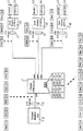
図10は、システム管理装置60の構成を示す図である。システム管理装置60は、CPU68と、ROM69と、例えばセットトップボックス40及び/又はSMU20にダウンロードされるVODソフトウェアプログラムのためのメモリであるRAM70と、ATMインターフェース61と、例えばテーブル手段としてのメモリ71とを備える。CPU68は、システム管理装置60の動作を制御する。システム管理装置60は、SMU20及びセットトップボックス40にオペレーションソフトウェアを供給するとともに、ATMスイッチ1における入力仮想チャンネルと出力仮想チャンネルとの関係を示すデータ用のテーブルを更新する。このようなシステム管理装置60は、記憶媒体マネージャ62、プログラムマネージャ67、サービス項目プロバイダ64、サービス項目グループ65、サーバルーティングマネージャ66に関する上述した全ての機能を実行する。
図11は、シーンのシーケンスを示す図であり、このシーケンスは、種々の伝送チャンネル上にビデオデータを表したものである。この具体例では、12本の(仮想)伝送チャンネルが用いられ、T=12であるが、チャンネル4〜12については簡略化のために図示を省略する。データグループは、スタガ記録データを記録している物理的記憶媒体21から再生され、これらの仮想チャンネルを介して、図6及び図7に示すのと同様に出力される。図11に示すように、シーンのシーケンスは、このような1シーンを有するビデオデータを入力のためのチャンネルを順次切り換えることによって、変更することができ、単純なVCR機能を実現することができる。例えば、シーン「2」が表示されている間にチャンネル1からチャンネル2に切り換えることにより、シーン「4」が表示され、したがって、早送りモードのようにシーン「3」をスキップすることができる。同様に、シーン「6」が表示されている間にチャンネル3からチャンネル1に切り換えることにより、シーン「5」が次に表示され、したがって、リバースモードを実現することができる。このような仮想チャンネル間の切換は、端末装置40からの制御データに応じたシステム管理装置60の制御の下に、ATMスイッチ1の変換テーブルを更新することによって、行うことができる。チャンネル間の切換が行われない場合、シーンの本来のシーケンスが続き、これは、単一チャンネル上のビデオデータのシーケンスである。
チャンネル3からチャンネル1に切り換えることにより、シーン5は、シーン6の後に表示される。このようにして、リバーススキップ再生が行われる。
図12は、端末装置40によって実行されるモザイク機能の具体例を示す図であり、モザイク機能では、あるシーケンスから選択されたシーンがモニタ受像機43に表示される。このように、ユーザは、入力装置44を介して対応する要求を発することにより、映画の頭以外に開始点を選択することができる。勿論、このようなモザイク機能を、1又は複数のナビゲーション装置30を介する、例えば複数の選択可能なビデオ番組のタイトルフレーム等の選択可能なサービス項目のメニューを表示するのに用いることもでき、この場合、このようなモザイク機能のために選択されたシーンは、仮想チャンネルを実時間で切り換えて、これらをビデオRAM50に同時に記憶することにより、又はSMU20に前もってモザイクビデオデータとして蓄積されているビデオデータを再生することにより、表示される。次に、物理的記憶媒体21上のビデオデータの記録フォーマットについて、図13〜15を参照して説明する。
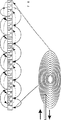
図13は、物理的記憶媒体21を示す図であり、ヘッド90が、物理的記憶媒体21の中心に対して進退自在にアーム91に取り付けられている。ここで、物理的記憶媒体21は光磁気ディスクからなる。光磁気ディスク21のデータトラックには、図13において物理的記憶媒体21の上側に示すスタガ記録シーケンス92のデータグループが記録されている。シーケンス92の上下の矢印は、ヘッド90が物理的記憶媒体21からデータグループを読み出す順序を示している。再生ヘッド90は、図に示すように、物理的記憶媒体21上を外周側に向かって、データグループをスキップしながら読みだし、スキップされたデータグループは、物理的記憶媒体21上を再生ヘッド90が内側に向かう際に読み出される。このように、SMU20のコントローラ26(図6参照)に送られるデータグループのシーケンスの終了と開始の間にはタイムロスが発生せずSMU20のコントローラ26によって要求された順番のデータグループの連続したフローが、確実に得られる。データグループが連続したフローとなっているので、容量が少ないバッファメモリを用いることができる。
上述したフォーマットで記憶媒体に記録されたビデオデータは、物理的記憶媒体21から再生され、SMU20から、3つの仮想チャンネルとしてのATMインターフェース29を介してATMスイッチ1に出力される。
図14において、同じ内容で反対のタイムラインを有する第1及び第2のビデオデータが、ディスクに記録されている。この場合、第1のビデオデータのデータグループと第2のビデオデータのデータグループは、インターリーブされている。第1のビデオデータは、セットトップボックスが、ノーマル再生モード、早送り再生モード、又は段階的早送り再生モードを要求したときに用いられる。一方、第2のビデオデータは、セットトップボックスがリバース再生モードを要求したときに用いられる。さらに、第1のビデオデータのデータグループを、ディスクの1トラックおきに記録しておくこともできる。このとき、第2のビデオデータのデータグループは、ディスクの残りのトラックに記録されている。そして、記録されている第1のビデオデータは、再生ヘッドを第1の方向に移動させることにより、ディスクの1トラックおきのトラックから再生される。記録されている第2のビデオデータは、再生ヘッドをこの第1の方向に移動させることにより、ディスクの残りのトラックから再生される。また、第1のビデオデータが再生された後、第1の方向と逆方向に第2のビデオデータを再生することもでき、図13に示す記録フォーマットと同様の効果が得られる。
第1及び第2のビデオデータがMPEG規格に準拠して符号化される場合、第2のビデオデータは、第1のビデオデータと逆の方法で符号化されなければならない。この場合、第2のビデオデータを上述のような逆方向で再生することはできない。図14Aの例では、フォワードデータグループ(1F、2F、3F、4F等)が図13と同様に4トラックおきに記録され、リバースデータグループ(12R、11R、10R、9R等)がそれぞれ2F、3F、4F等の前に4トラックおきに記録されているので、フォワード再生及びリバース再生の両方において、ヘッドの移動距離は最小化される。また、ディスクの外周部の6F、7F、8F及び7R、6R、5Rや、内周部の12F、1F、2F及び1R、12R、11Rからも明らかなように、ディスクの内外周部においるヘッドの移動距離は最小化される。
図15は、モニタ受像機に表示されたビデオデータのシーケンスを示す図であり、このシーケンスは、フォワード及び/又はリバース再生モードを得るための図14に示した記録フォーマット及び読出シーケンスを用いることによって、また図13、14、14Aに例示したスタガ形式でデータを記録するために異なる仮想チャンネルに対してそれぞれ送受信を行うことによって、得られる。
マルチキャスト機能について、図16を参照しながら説明する。マルチキャスト機能では、図1に示すシステム管理装置60は、ビデオデータの配信も管理する。システム管理装置60は、サービス中の1つ以上の端末装置40から、SMU20のうちの1つから送信されているのと同じビデオデータ及び/又はオーディオデータ、又は他の端末装置40から要求されているのと同じビデオデータ及び/又はオーディオデータを供給するように依頼するディマンドデータを受信したとき、SMU20からの選択されたビデオデータの入力仮想チャンネルと、受信したディマンドデータに応じて生成されるビデオデータ及び/又はオーディオデータを要求する端末装置40の出力仮想チャンネルとの情報を含む配信制御データを、ATMスイッチ1に出力する。例えば、端末装置STB−3が、他の端末装置STB−1に要求によりSMU20から入力仮想チャンネル「vc1」及び出力仮想チャンネル「vc7」を介して伝送されるのと同じビデオデータ「ビデオ1」、「ビデオ2」、「ビデオ3」を要求すると、システム管理装置60は、更新された変換テーブルをATMスイッチ1に出力し、「ビデオ1」「ビデオ2」「ビデオ3」を伝送するATMパケットのヘッダは、ATMスイッチにて、出力仮想チャンネル「vc7」に対応するヘッダに置き換えられるだけではなく、端末装置STB−3によって指定されている出力仮想チャンネル「vc8」に対応するヘッダにも置き換えられる。したがって、「ビデオ1」、「ビデオ2」、「ビデオ3」を含むATMパケットは、端末装置40STB−1及び端末装置STB−3の両方に同時に供給される。
図17に示す通信シーケンスは、SMU20からセットトップボックス40へのビデオーデータのフローを確立する方法を示している。まず、ステップ1において、ユーザは、自分の入力装置44を介して、システムにアクセスした旨をSTBで示されているセットトップボックス40に通知する。ステップ2において、セットトップボックス40は、ビデオオンディマンド、ゲーム、テレビ等、どのような種類のサービスをユーザが選択したいのかをユーザに尋ねることによって、応答する。このような選択可能なオプションは、セットトップボックス40のメモリに記憶されているようにしてもよい。次に、ステップ3において、ユーザは、自分の選択を自分の入力装置44を介してセットトップボックス40に入力し、そして、セットトップボックス40は、図中NAVIで示されるナビゲーション装置30と通信を行う。以下の説明は、ユーザが、1又は複数のナビゲーション装置30が適用されたビデオオンディマンドサービスメニューを選択した場合についてである。図には、分かり易いように1つのナビゲーション装置30のみを示している。
ステップ5において、ナビゲーション装置30は、ナビゲーション装置30がアクセスできる選択可能なビデオサービスのメニューをセットトップボックス40に供給する。このメニューには、セットトップボックス40が、他のビデオサービスにアクセスできる他のナビゲーション装置30を参照するオプションを設けるようにしてもよい。次のステップ6において、セットトップボックス40は、モニタ受像機43にメニューを表示することにより、ユーザにメニューを提供する。ステップ7において、ユーザは、自分の入力装置44を介して自分の選択、例えば異なるメニューの要求を入力する。ステップ8において、この要求は、ナビゲーション装置30に供給され、ステップ9において、ナビゲーション装置30は、これに応じて、新たな選択メニューをセットトップボックス40に供給する。ステップ7〜10は、ステップ10においてセットトップボックス40によりモニタ受像機43に表示されたメニューが、ステップ11で示すユーザが選択したいビデオ番組のオプションを含むまで、何度も繰り返される。ステップ12において、セットトップボックス40は、SIPで示されるサービス項目プロバイダ64に対して、サービス項目プロバイダ64のアドレスに対応する所定の公衆アドレスをセットトップボックスに供給するように要求する。ステップ13において、サービス項目プロバイダ64は、まず、SIGで示されるサービス項目グループ65に対して、ビデオストリームが確立されるセットトップボックス40による最適な処理に必要とされる制御データをセットトップボックス40に供給するように要求し、ステップ14において、この制御ソフトウェアは、セットトップボックス40にダウンロードされる。これにより、セットトップボックス40はVCR機能に関するコマンドを発することが可能となり、ステップ15において、第1の再生コマンドがサービス項目プロバイダ64に対して発せられる。ステップ16において、サービス項目プロバイダ64は、要求に応じた第1の提供可能なビデオストリーム、例えばSMU1で示される記憶媒体装置20からのビデオストリームを検索し、ATMスイッチ1内の仮想チャンネルテーブルを書き換えることによって、記憶媒体装置20とセットトップボックス40を接続するように、ATMSWで示されるATMスイッチ1を設定する。ステップ17及び18において、要求されたビデオストリームは、ATMスイッチ1を介してセットトップボックス40にルーティングされ、要求されたビデオ番組がモニタ受像機43に表示される。
図18において、システムの動的な再構成が行われる。このタイミングチャートのライン13にて、サービス項目グループ(SIG)は、SMUインストーラの新たなインスタンスを生成し、送信元SMUの数、送信元SMUの数、その他のパラメータを供給する。ライン14にて、SMUインストーラは、送信先であるSMU1に対するダウンロード動作を実行し、SMU1をデータ待ちの状態にしておく。ライン15にて、SMUインストーラは、送信元であるSMU2に、送信先であるSMU1へのデータ供給を開始するように要求する。ライン16にて、要求されたデータは、SMU2からSMU1へ転送される。ライン17にて、SMU2は、データ転送が完了したことをSMUインストーラに報告する。ライン18にて、SMUインストーラは、SMU1がデータを供給する準備ができたことをSIGに通知し、その後、SMUインストーラは、消滅する。ライン19にて、SIGは、SMU1に、ある仮想チャンネルへのデータ供給を開始するように要求し、このようなデータがエンドユーザに供給される。
以上の説明では、多くの特徴及び詳細について、好ましい実施例を参照しながら説明したが、本発明は、そのような好ましい実施例の説明に限定されるものではない。本発明の権利範囲は、以下の請求の範囲によって特定されるものである。Background art
In a conventional cable TV system, video data is supplied from a distributor to a monitor receiver of many viewers via a cable. In recent years, many programs have been distributed from multiple cable TV operators via multiple channels, but users or viewers do not have to wait until the program they want to watch starts and is transmitted via the selected channel. Not be.
In recent years, an interactive video system has been proposed. In such an interactive video system, a viewer can select a movie displayed on a monitor receiver. In such a video-on-demand system, a direct connection to the user's monitor receiver or terminal is established, after which the end user can watch the requested movie.
With this known system, it is virtually impossible to expand the system after the system has been built at the distributor, for example. When the number of members increases and the number of required videos increases in such a system, a new interactive video system must be constructed.
Disclosure of the invention
A storage medium device according to the present invention includes storage means for storing information data, table means for storing data indicating a relationship between routing information and information data, and memory for storing program data for controlling the operation of the storage medium device. Means, control means for controlling the storage means, the table means, and the memory means based on the program data; and at least one interface for transmitting information data to the routing means in the form of packets together with the routing information. The information data is video and / or audio data, the routing information includes virtual channel information of the interface, control data for controlling the selected operation mode is received by the storage medium device via the interface, and control means Controls the storage means so that the information data is reproduced in the selected operation mode by switching the virtual channel of the interface based on the received control data.
The storage medium device according to the present invention can be expanded by adding and connecting one or more storage medium devices to the system. By standardizing at least one packet format as an interface for information data and routing information, the storage means of the storage medium device according to the present invention can be configured to include at least one hard disk, at least one magneto-optical disk, a video tape, and / or It can be any type of storage medium, such as other media.
Program data is downloaded, for example, from an interactive system, whereby only minimal software is stored on the storage media device.
The information data includes, for example, video data and / or audio data, but the present invention is not limited to this use. The storage medium device according to the present invention can be used for video games, library functions, and data banks, but the most suitable field of application is video-on-demand services.
The interface is, for example, an ATM interface. The principles and standards of ATM (Asynchronous Transfer Mode) are described in Recommendations I.150 and I.327 issued by the International Telecommunication Union in March 1993. ATM is generally used for a specific packet-oriented transfer mode using asynchronous time division multiplexing technology. The multiplexed information flow is incorporated into solid-sized blocks called cells. One cell includes an information area and a header. The main function of the header is to identify cells belonging to the same virtual channel in asynchronous time division multiplexing.
The storage medium device according to the present invention performs a still image mode operation, a fast-forward playback mode operation, a reverse playback mode operation, and a mosaic mode operation, for example, as in a video cassette recorder (VCR).
Further, an information providing apparatus according to the present invention includes one or more storage media devices, one or more terminal devices, and at least one ATM switch that connects the storage media devices to the terminal devices. A storage unit for storing information data; a table unit for storing data indicating a relationship between routing information and the information data; a memory unit for storing program data for controlling operation of the storage medium unit; A control unit that controls the storage unit, the table unit, and the memory unit based on the data and outputs a control signal to the terminal device; and transmits the information data to the ATM switch in one or more ATM packet formats together with the routing information and the control signal. And an ATM interface for receiving program data for operating the storage medium device from the ATM switch in an ATM packet format. The information data is video and / or audio data, the routing information includes virtual channel information of the ATM interface, control data for controlling the selected operation mode is received by the storage medium device via the ATM interface, and The means controls the storage means such that the information data is reproduced in the selected operation mode by switching the virtual channel of the ATM interface based on the received control data.
Further details, features and advantages of the invention are described below with reference to the drawings, which show embodiments of the invention.
[Brief description of the drawings]
FIG. 1 is a diagram showing the configuration of the entire system for information on demand.
FIG. 2 is a diagram showing a first specific configuration of the storage medium device.
FIG. 3 is a diagram showing a second specific configuration of the storage medium device.
FIG. 4 is a schematic diagram showing a control flow and a data flow in the storage medium device shown in FIGS. 2 and 3.
FIG. 5 is a diagram showing a third specific configuration of the storage medium device.
FIG. 6 is a diagram showing a storage medium device corresponding to the storage medium device shown in FIG. 2 together with data groups obtained therefrom.
FIG. 7 is a diagram showing the timing of the ATM interface in the storage medium device.
FIG. 8 is a diagram showing a specific configuration of the navigation system shown in FIG.
FIG. 9 is a diagram showing a specific configuration of the end user device shown in FIG.
FIG. 10 is a diagram showing a specific configuration of the system management device shown in FIG.
FIG. 11 is a diagram showing a basic reproduction function for stagger recording.
FIG. 12 is a diagram showing a mosaic menu function.
FIGS. 13, 14, and 14A are diagrams each showing a recording format of a recording track of a magneto-optical disk.
FIG. 15 is a diagram showing the reproduction of data recorded in the staggered format of FIG.
FIG. 16 is a diagram illustrating an example of multicasting.
FIG. 17 is a diagram showing an example of a series of communication steps in the system according to the present invention.
FIG. 18 is a diagram showing another example of a series of communication steps in the preferred embodiment of the system according to the present invention.
BEST MODE FOR CARRYING OUT THE INVENTION
The following description with reference to the drawings describes a combination of hardware and software. Some hardware components are combined into a single component to perform functions such as a CPU by time division multiplexing. Also, the connections between logical (software) units are actually more complex than those shown schematically in the figure.
FIG. 1 is a diagram showing an overall configuration of a preferred embodiment of an interactive communication system according to the present invention. This system uses an ATM switch 1 (e.g., ForeRunner (TM) ASX-200 manufactured by ForeSystem Inc., Warrendale, PA, USA) (ForeRunner, Fore Systems Inc., Warrendale, Pennsylvania, USA). TM ASX-200)), a storage medium device 20 (SMU), a
The interactive communication system is described below with particular reference to a specific example of providing a video-on-demand (VOD) service to a user. It should be noted that the same can be applied to uses such as tele-shopping, games, and other information exchange. Such a service is generally called an information-on-demand service.
In the interactive communication system shown in FIG. 1, video signals and / or audio signals are stored in the
In FIG. 1, a
The
The
The main feature of the interactive communication system according to the preferred embodiment of the present invention is that there is no limitation on the hardware used or the operating system installed. Since each communication operation is performed by sending a control software program dedicated to those operations to a receiver and / or a transmitter, the receiver and / or the transmitter downloads the control software program, and then receives and / or transmits the control software program. Alternatively, transmission can be optimally performed.
In the embodiment of FIG. 1, at least one of the
When the
The interactive communication system includes, for example, a plurality of (distribution) SMUs. In this system, if the number of
In the preferred embodiment of the present invention, the number of end users can be monitored during operation, and the configuration can be significantly modified to prevent system overload. When the number of end users increases, the new distribution SMU loads video data and / or audio data from the storage SMU or another distribution SMU.
The
The user selects a desired navigation service, and connects the
The user can point a desired video program from the menu displayed on the
In another embodiment, not shown, the
After receiving the identification data from the set-
The
As described above, the physical storage medium may be any of a hard disk, a magneto-optical disk, and a tape on which a video movie is recorded.
The
Control data from the
The
In an embodiment, not shown, where a public ATM switch is used in combination with a private ATM switch, the virtual channel connection of the public ATM switch is established using a public address at the start of the service.
The VOD operation is performed when the
In the case of the VCR operation, the physical storage medium is, for example, a hard disk that operates faster than the other physical storage media described above. Also, a magneto-optical disk can be used, but in this case, information is recorded in a staggered format described later.
The
The
If multiple storage media managers 62 are used, each storage media manager 62 presents the
The service item group 65 downloads an appropriate downloadable software program to the set-top box based on, for example, an internal table indicating the relationship between the service item identifier and the service item provider. The service item group 65 determines which downloadable software is appropriate for the next operation of the set-top box based on tables in the service item group, for example, when supplied with a request from a service item provider.
Even when the storage medium manager 62 is not functioning, the reproduced video data and / or audio data are output directly to the
Next, a full VCR function, for example, a fast-forward playback mode, a reverse playback mode, a fast-forward reverse playback mode, and a still image mode will be described. In the full VCR function, for example, a high-speed storage medium such as a hard disk is used. The high-speed storage medium is installed in one or more of the SMUs. At the start of the video-on-demand service, the video data and / or audio data of the selected video program or the video program with the possibility of the VCR function from the
When the set-
Here, a specific example of communication established between the
Then, the service item provider 64 (SIP-1) confirms the current time, and, based on an internal table, the next deliverable time point 0:10 as the start time of the movie, and video data and / or audio of the movie. The number “2” specifying the
The service item provider 64 (SIP-1) updates the conversion table in the
When the terminal device 40 (STB-2) requests one of the service item providers 64 (SIP-1) for the full VCR function, the service item provider 64 (SIP-1) returns from an internal table. Delivery control data including a number “4” specifying the
The service item provider 64 (SIP-1) updates the conversion table in the
The interactive communication system as described above is suitable for use as a platform of a system including many server owners, navigation device owners, system management device owners, and users. In this case, one party can use one or
In FIG. 1, the entire system is configured around a
Next, each device will be described in detail.
FIG. 2 is a diagram showing the configuration of the
The
The
The
The
FIG. 3 is a diagram showing another configuration of the
FIG. 4 schematically shows a control flow and a data flow in the
FIG. 5 is a diagram showing a third configuration of the
FIG. 6 shows an
The video data recorded as described above is repeatedly played back sequentially from the
FIG. 8 is a diagram showing a configuration of the
FIG. 9 is a diagram showing the configuration of the terminal device, that is, the set-
FIG. 10 is a diagram showing a configuration of the
FIG. 11 is a diagram illustrating a sequence of scenes, which represents video data on various transmission channels. In this specific example, twelve (virtual) transmission channels are used and T = 12, but
By switching from
FIG. 12 is a diagram illustrating a specific example of the mosaic function executed by the
FIG. 13 is a view showing the
The video data recorded on the storage medium in the format described above is reproduced from the
In FIG. 14, first and second video data having the same content but opposite timelines are recorded on a disc. In this case, the data group of the first video data and the data group of the second video data are interleaved. The first video data is used when the set-top box requests a normal playback mode, a fast-forward playback mode, or a step-by-step fast-forward playback mode. On the other hand, the second video data is used when the set-top box requests the reverse playback mode. Further, the data group of the first video data can be recorded every other track of the disc. At this time, the data group of the second video data is recorded on the remaining tracks of the disc. Then, the recorded first video data is reproduced from every other track of the disk by moving the reproducing head in the first direction. The recorded second video data is reproduced from the remaining tracks of the disc by moving the reproducing head in the first direction. Further, after the first video data is reproduced, the second video data can be reproduced in a direction opposite to the first direction, and the same effect as the recording format shown in FIG. 13 can be obtained.
If the first and second video data are coded according to the MPEG standard, the second video data must be coded in the opposite way to the first video data. In this case, the second video data cannot be reproduced in the reverse direction as described above. In the example of FIG. 14A, the forward data groups (1F, 2F, 3F, 4F, etc.) are recorded every four tracks as in FIG. 13, and the reverse data groups (12R, 11R, 10R, 9R, etc.) are 2F, 3F, respectively. , 4F, etc., are recorded every fourth track, so that the moving distance of the head is minimized in both the forward reproduction and the reverse reproduction. Further, as is clear from 6F, 7F, 8F and 7R, 6R and 5R on the outer peripheral portion of the disk and 12F, 1F, 2F and 1R, 12R and 11R on the inner peripheral portion, the disk is located on the inner and outer peripheral portions of the disk. The moving distance of the head is minimized.
FIG. 15 is a diagram showing a sequence of video data displayed on the monitor receiver, which sequence is obtained by using the recording format and the reading sequence shown in FIG. 14 to obtain the forward and / or reverse playback mode. In order to record data in the staggered format illustrated in FIGS. 13, 14, and 14A, the data is transmitted and received for different virtual channels.
The multicast function will be described with reference to FIG. In the multicast function, the
The communication sequence shown in FIG. 17 shows a method for establishing a flow of video data from the
In
In FIG. 18, a dynamic reconfiguration of the system is performed. At
Although many features and details have been described above with reference to preferred embodiments, the present invention is not limited to the description of such preferred embodiments. The scope of the present invention is specified by the following claims.
Claims (7)
情報データを記憶する記憶手段と、
ルーティング情報と上記情報データの関係を示すデータを記憶するテーブル手段と、
当該記憶媒体装置の動作を制御するプログラムデータを記憶するメモリ手段と、
上記プログラムデータに基づいて、上記記憶手段、テーブル手段及びメモリ手段を制御する制御手段と、
上記情報データを、上記ルーティング情報とともにパケット形式でルーティング手段に送信する少なくとも1つのインターフェースとを備え、
上記情報データは、ビデオ及び/又はオーディオデータであり、
上記ルーティング情報は、上記インターフェースの仮想チャンネル情報を含み、
選択された動作モードを制御する制御データが上記インターフェースを介して当該記憶媒体装置に受信され、上記制御手段は、受信された制御データに基づいて、上記インターフェースの仮想チャンネルを切り換えることにより、上記情報データが選択された動作モードで再生されるように上記記憶手段を制御することを特徴とする記憶媒体装置。In the storage medium device,
Storage means for storing information data;
Table means for storing data indicating a relationship between the routing information and the information data,
Memory means for storing program data for controlling the operation of the storage medium device;
Control means for controlling the storage means, the table means, and the memory means based on the program data;
At least one interface for transmitting the information data together with the routing information in a packet format to a routing means,
The information data is video and / or audio data,
The routing information includes virtual channel information of the interface,
Control data for controlling the selected operation mode is received by the storage medium device via the interface, and the control means switches the virtual channel of the interface based on the received control data, thereby obtaining the information. A storage medium device which controls the storage means so that data is reproduced in a selected operation mode.
1以上の端末装置と、
上記記憶媒体装置を端末装置に接続する少なくとも1つのATMスイッチとを備え、
上記記憶媒体装置は、
情報データを記憶する記憶手段と、
ルーティング情報と上記情報データの関係を示すデータを記憶するテーブル手段と、
上記記憶媒体装置の動作を制御するプログラムデータを記憶するメモリ手段と、
上記プログラムデータに基づいて、上記記憶手段、テーブル手段及びメモリ手段を制御し、制御信号を端末装置に出力する制御手段と、
上記情報データを、上記ルーティング情報及び制御信号とともに1以上のATMパケット形式で上記ATMスイッチに送信し、該ATMスイッチからATMパケット形式で上記記憶媒体装置の動作のためのプログラムデータを受信するATMインターフェースとを備え、
上記情報データは、ビデオ及び/又はオーディオデータであり、
上記ルーティング情報は、上記ATMインターフェースの仮想チャンネル情報を含み、
選択された動作モードを制御する制御データが上記ATMインターフェースを介して上記記憶媒体装置に受信され、上記制御手段は、受信された制御データに基づいて、上記ATMインターフェースの仮想チャンネルを切り換えることにより、上記情報データが選択された動作モードで再生されるように上記記憶手段を制御することを特徴とする情報提供装置。One or more storage media devices;
One or more terminal devices;
At least one ATM switch for connecting the storage medium device to a terminal device,
The storage medium device,
Storage means for storing information data;
Table means for storing data indicating a relationship between the routing information and the information data,
Memory means for storing program data for controlling the operation of the storage medium device;
A control unit that controls the storage unit, the table unit, and the memory unit based on the program data, and outputs a control signal to a terminal device;
An ATM interface for transmitting the information data together with the routing information and the control signal in the form of one or more ATM packets to the ATM switch, and receiving program data for operating the storage medium device in the form of an ATM packet from the ATM switch. With
The information data is video and / or audio data,
The routing information includes virtual channel information of the ATM interface,
Control data for controlling the selected operation mode is received by the storage medium device via the ATM interface, and the control means switches a virtual channel of the ATM interface based on the received control data, An information providing device, wherein the storage means is controlled so that the information data is reproduced in a selected operation mode.
Applications Claiming Priority (3)
| Application Number | Priority Date | Filing Date | Title |
|---|---|---|---|
| EP95200818A EP0735762B1 (en) | 1995-03-31 | 1995-03-31 | Storage medium unit for storing information data, preferably video data and/or audio data |
| EP95200818.3 | 1995-03-31 | ||
| PCT/EP1996/001413 WO1996031058A1 (en) | 1995-03-31 | 1996-03-28 | Storage medium unit for storing information data, preferably video data and/or audio data |
Publications (2)
| Publication Number | Publication Date |
|---|---|
| JPH11509952A JPH11509952A (en) | 1999-08-31 |
| JP3557217B2 true JP3557217B2 (en) | 2004-08-25 |
Family
ID=8220152
Family Applications (1)
| Application Number | Title | Priority Date | Filing Date |
|---|---|---|---|
| JP52895396A Expired - Fee Related JP3557217B2 (en) | 1995-03-31 | 1996-03-28 | Storage medium device for storing information data such as video data and / or audio data and information providing device |
Country Status (9)
| Country | Link |
|---|---|
| US (1) | US6411773B1 (en) |
| EP (1) | EP0735762B1 (en) |
| JP (1) | JP3557217B2 (en) |
| KR (1) | KR19980703632A (en) |
| AT (1) | ATE194447T1 (en) |
| AU (1) | AU5498596A (en) |
| DE (1) | DE69517793T2 (en) |
| TW (1) | TW312880B (en) |
| WO (1) | WO1996031058A1 (en) |
Families Citing this family (10)
| Publication number | Priority date | Publication date | Assignee | Title |
|---|---|---|---|---|
| US6771876B1 (en) * | 1998-11-10 | 2004-08-03 | Sony Corporation | Data recording and/or reproducing apparatus, adjustment volume in data recording and/or reproducing apparatus, port operating method in data recording and/or reproducing apparatus and selective indicating method for adjustment volume in data recording and/or reproducing |
| US6796555B1 (en) * | 1999-07-19 | 2004-09-28 | Lucent Technologies Inc. | Centralized video controller for controlling distribution of video signals |
| US7240359B1 (en) * | 1999-10-13 | 2007-07-03 | Starz Entertainment, Llc | Programming distribution system |
| US8806549B1 (en) * | 1999-10-13 | 2014-08-12 | Starz Entertainment, Llc | Pre-storing a portion of a program to allow user control of playback |
| US7237033B2 (en) | 2001-04-30 | 2007-06-26 | Aol Llc | Duplicating switch for streaming data units to a terminal |
| US8572278B2 (en) * | 2001-04-30 | 2013-10-29 | Facebook, Inc. | Generating multiple data streams from a single data source |
| US7124166B2 (en) | 2001-04-30 | 2006-10-17 | Aol Llc | Duplicating digital streams for digital conferencing using switching technologies |
| US20040128693A1 (en) | 2002-12-27 | 2004-07-01 | Weigand Gilbert G. | System and method for enabling access to content through a personal channel |
| US8028092B2 (en) | 2002-06-28 | 2011-09-27 | Aol Inc. | Inserting advertising content |
| US20040258390A1 (en) * | 2003-06-20 | 2004-12-23 | Olson Anthony M. | Systems and methods for PVR real time distributed storage, playback, and archival of programs on a network |
Family Cites Families (6)
| Publication number | Priority date | Publication date | Assignee | Title |
|---|---|---|---|---|
| US5373288A (en) * | 1992-10-23 | 1994-12-13 | At&T Corp. | Initializing terminals in a signal distribution system |
| EP0625857B1 (en) * | 1993-05-19 | 1998-06-24 | ALCATEL BELL Naamloze Vennootschap | Video server |
| DE69317267T2 (en) * | 1993-05-19 | 1998-06-25 | Alsthom Cge Alcatel | Network for video on request |
| CA2127347A1 (en) * | 1993-07-07 | 1995-01-08 | Donald F. Hooper | Segmented video on-demand system |
| US5442390A (en) * | 1993-07-07 | 1995-08-15 | Digital Equipment Corporation | Video on demand with memory accessing and or like functions |
| US5541738A (en) * | 1994-04-12 | 1996-07-30 | E. Guide, Inc. | Electronic program guide |
-
1995
- 1995-03-31 DE DE69517793T patent/DE69517793T2/en not_active Expired - Lifetime
- 1995-03-31 AT AT95200818T patent/ATE194447T1/en not_active IP Right Cessation
- 1995-03-31 EP EP95200818A patent/EP0735762B1/en not_active Expired - Lifetime
- 1995-11-03 TW TW084111671A patent/TW312880B/zh not_active IP Right Cessation
-
1996
- 1996-03-28 AU AU54985/96A patent/AU5498596A/en not_active Abandoned
- 1996-03-28 JP JP52895396A patent/JP3557217B2/en not_active Expired - Fee Related
- 1996-03-28 US US08/930,474 patent/US6411773B1/en not_active Expired - Lifetime
- 1996-03-28 KR KR1019970707031A patent/KR19980703632A/en not_active Application Discontinuation
- 1996-03-28 WO PCT/EP1996/001413 patent/WO1996031058A1/en not_active Application Discontinuation
Also Published As
| Publication number | Publication date |
|---|---|
| EP0735762A1 (en) | 1996-10-02 |
| AU5498596A (en) | 1996-10-16 |
| DE69517793T2 (en) | 2000-12-28 |
| KR19980703632A (en) | 1998-12-05 |
| US6411773B1 (en) | 2002-06-25 |
| JPH11509952A (en) | 1999-08-31 |
| DE69517793D1 (en) | 2000-08-10 |
| EP0735762B1 (en) | 2000-07-05 |
| TW312880B (en) | 1997-08-11 |
| WO1996031058A1 (en) | 1996-10-03 |
| ATE194447T1 (en) | 2000-07-15 |
Similar Documents
| Publication | Publication Date | Title |
|---|---|---|
| JP3557216B2 (en) | Interactive communication system | |
| EP0735763B1 (en) | A system for information on demand | |
| EP0735538B1 (en) | A storage medium unit and video service system having a staggered recording | |
| JP3557217B2 (en) | Storage medium device for storing information data such as video data and / or audio data and information providing device | |
| US6128650A (en) | Video service system with VCR function | |
| JP3557219B2 (en) | Information-on-demand system with multicasting function | |
| JP3557218B2 (en) | Information service system | |
| EP0735760B1 (en) | A system for serving information including an archive and delivery storage medium unit | |
| EP0735758B1 (en) | A system for serving information including a storage media manager | |
| EP0735764B1 (en) | A system for information on demand, including respective control means |
Legal Events
| Date | Code | Title | Description |
|---|---|---|---|
| A521 | Request for written amendment filed |
Free format text: JAPANESE INTERMEDIATE CODE: A523 Effective date: 20040302 |
|
| TRDD | Decision of grant or rejection written | ||
| A01 | Written decision to grant a patent or to grant a registration (utility model) |
Free format text: JAPANESE INTERMEDIATE CODE: A01 Effective date: 20040420 |
|
| A61 | First payment of annual fees (during grant procedure) |
Free format text: JAPANESE INTERMEDIATE CODE: A61 Effective date: 20040517 |
|
| R150 | Certificate of patent or registration of utility model |
Free format text: JAPANESE INTERMEDIATE CODE: R150 |
|
| FPAY | Renewal fee payment (event date is renewal date of database) |
Free format text: PAYMENT UNTIL: 20090521 Year of fee payment: 5 |
|
| FPAY | Renewal fee payment (event date is renewal date of database) |
Free format text: PAYMENT UNTIL: 20090521 Year of fee payment: 5 |
|
| FPAY | Renewal fee payment (event date is renewal date of database) |
Free format text: PAYMENT UNTIL: 20100521 Year of fee payment: 6 |
|
| FPAY | Renewal fee payment (event date is renewal date of database) |
Free format text: PAYMENT UNTIL: 20100521 Year of fee payment: 6 |
|
| FPAY | Renewal fee payment (event date is renewal date of database) |
Free format text: PAYMENT UNTIL: 20110521 Year of fee payment: 7 |
|
| FPAY | Renewal fee payment (event date is renewal date of database) |
Free format text: PAYMENT UNTIL: 20120521 Year of fee payment: 8 |
|
| FPAY | Renewal fee payment (event date is renewal date of database) |
Free format text: PAYMENT UNTIL: 20120521 Year of fee payment: 8 |
|
| FPAY | Renewal fee payment (event date is renewal date of database) |
Free format text: PAYMENT UNTIL: 20130521 Year of fee payment: 9 |
|
| R250 | Receipt of annual fees |
Free format text: JAPANESE INTERMEDIATE CODE: R250 |
|
| R250 | Receipt of annual fees |
Free format text: JAPANESE INTERMEDIATE CODE: R250 |
|
| LAPS | Cancellation because of no payment of annual fees |