【0001】
【発明の属する技術分野】
本発明は車両用シートに関し、特にシートクッションを前方へ反転させて生じた空間内にシートバックを前倒させて、前倒したシートバックの背面から反転したシートクッションの底面へと続くフラット面を形成できるようにした、いわゆるダブルフラット型の車両用シートの構造改良に関する。
【0002】
【従来の技術】
特開平10−226253号公報には、図9に示すように、シートクッションS1の前端下面をヒンジ41によってアッパレール42に連結して、ヒンジ軸43を中心にしてシートクッションS1を矢印のように前方へ起立回動させ、この時生じた空間内へシートバックS2を前倒させて荷室フロアFを拡大できるようにした車両用シートが開示されている。そして、この車両用シートにおいては、左右のアッパレール42(一方のみ図示)の前端部と後端部上にそれぞれクロスフレーム44,45を架け渡して、これらクロスフレーム44,45を、起立回動させる前の使用状態(図9の状態)のシートクッションS1の底面に接する位置に設けて、シートクッションS1の荷重を支持するようにしている。
【0003】
【発明が解決しようとする課題】
しかし、上記従来の構造では、所定の座面高さでシートクッションの厚さを十分確保しようとすると、スペース上、クロスフレーム44,45の断面を十分大きく確保することができないために、前後のクロスフレーム44,45と左右のアッパレール42とで構成される略四角形のフレーム体4の強度が十分でないという問題があった。
【0004】
そこで本発明はこのような課題を解決するもので、シートクッションの厚さを十分確保することが可能であるとともに、フレーム体の強度も向上させることが可能な車両用シートを提供することを目的とする。
【0005】
【課題を解決するための手段】上記目的を達成するために、本第1発明では、車両フロアに設けた1つのフレーム体(2)上に左右に近接して2つのシートクッション(S1)を配置するとともに、シートクッション(S1)の前端をそれぞれフレーム体(2)に軸支し、シートクッション(S1)をその前端を中心に前方へ跳ね上げ回転可能とした車両用シートにおいて、上記フレーム体(2)を、前枠(25)、後枠(26)および左右の側枠(21,22)よりなる平面視で略長方形の外枠と、該外枠内を前後方向へ延びて前枠(25)と後枠(26)とを結合する縦枠(27)とで構成し、後枠(26)をシートクッション(S1)の後方に配置し、シートクッション(S1)の左右の側縁を側枠(21,22)と縦枠(27)とで支持するとともに、上記縦枠(27)は、両シートクッション(S1)間に配置される本体部(273)と、該本体部(273)より側方へ突出し、シートクッション(S1)の側縁が載置される受け部(271,272)とで構成される。
【0006】
本第1発明においては、後枠を、従来のようなシートクッションに接してこれの荷重を受ける位置から、シートクッションの後方位置へ移動させて、シートクッションの荷重を、外枠の側枠と外枠内に設けた縦枠とで受けるようにしたから、後枠の断面を十分大きくすることができ、フレーム体の十分な強度を確保することが可能であるとともにシートクッションの厚さを十分確保することができる。そして、縦枠の本体部を両シートクッション間に配置したから、本体部の断面積を大きくすることにより、シートクッションの厚さに影響をおよぼすことなく、フレーム体の強度を十分確保することができる。
【0009】
本第2発明では、上記縦枠(27)の前端に設けたブラケット(33)に一本の軸部材(38)を設け、該軸部材(38)の両端に各シートクッション(S1)の前端内側部をそれぞれ回動可能に結合する。
【0010】
本第2発明においては、各シートクッションが共通の一本の軸部材を中心にして回動させられるから、跳ね上げ状態における両者の建付け精度を良好に確保することができる。
【0011】
なお、上記カッコ内の符号は、後述する実施形態に記載の具体的手段との対応関係を示すものである。
【0012】
【発明の実施の形態】
図1には長椅子シート1のフレーム構造を示す。長椅子シート1は長手方向(図1の左右方向)へ6:4程度の比で分割されて左右のシート部11,12となっており、各シート部11,12にはそれぞれシートクッションS1を載置するためのシートクッションパネル13,14と、シートバックS2を保持するためのシートバックパネル15,16とが設けられている。各シートバックパネル15,16はその下端両側部が公知のリクライニング機構17,18,19,20によって、後述するフレーム体2に結合されて前倒可能となっている。
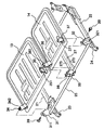
【0013】
フレーム体2の詳細を図2に示す。フレーム体2は各シート部11,12のシートクッションS1(図1)の外周を連ねて平面視で略長方形に形成されており、その左右の側枠21,22はスライドレールのアッパレールにより構成されている。各アッパレール21,22は車両フロア上に配設されたロアレール23,24に沿って前後方向(図2の斜め左右方向)へ摺動可能であり、各アッパレール21,22の後端部にはリクライニング機構17,20を構成するロアアーム171,201が固定されている。各ロアアーム171,201にはリクライニング機構17,20を構成するアッパアーム172,202が回動可能かつ所定位置でロック可能に結合されており、このアッパアーム172,202に各シートバックパネル15,16(図1)の外側下端部が固定されている。また、各アッパレール21,22の前端部にはブラケット31,32が突設されている。
【0014】
フレーム体2の前枠25と後枠26はそれぞれパイプ材で構成されており、前枠25は左右のアッパレール21,22の前端部間に架設されてこれらを結合している。また、後枠26は図1に示すように、シートクッションパネル13,14の後縁よりも後方の、シートクッションS1の荷重を受けない位置に配設されて左右のアッパレール21,22の後端部に設けたブラケット211,221間に架設され、これらを結合している。このように、後枠26は、従来のようなシートクッションS1に接してこれの荷重を受ける位置からは外れた位置に設けられているから、十分な強度を有する大径のパイプ材を使用することができ、フレーム体の強度を十分に確保することができる。
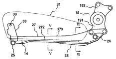
【0015】
フレーム体2には縦枠27が設けられ、縦枠27は、左右のシート部11,12のシートクッションS1(図1)の境界に沿って延びて、前枠25と後枠26を結合している。縦枠27の側面視を図4に示すとともに、その断面形状を図5、図6に示す。縦枠27はその本体部273の前半部(図4の左半部)が下方へ開放する略逆U字形断面(図5)となっており、その下端両側は水平に屈曲して受け部としての受けフランジ部271,272となっている。縦枠27の本体部273は前端から後方へ向けて次第にその高さが高くなるとともに、その後半部では図6に示すように浅い略U字形断面の補強板28がその開口縁フランジ部281,282で上記受けフランジ部271,272に下方から接合されて閉断面構造となっている。
【0016】
このような縦枠27の後端左右位置にはそれぞれリクライニング機構18,19を構成するロアアーム181,191が固定されており(図2)、各ロアアーム181,191にはリクライニング機構18,19を構成するアッパアーム182,192が回動可能かつ所定位置でロック可能に結合されて、各アッパアーム182,192に各シートバックパネル15,16の内側下端部が固定されている(図1)。車両の急加減速時にシートバックパネル15,16からリクライニング機構18,19を介して縦枠27に大きな荷重が印加しても、前述のように縦枠27の本体部273の後半部は閉断面構造となっているとともに、当該後半部は前半部に比して断面形状が上下方向へ延びているから(図5、図6参照)、上記荷重に対して十分な耐久性を発揮する。
【0017】
縦枠27の前端にはブラケット33が立設されている(図3)。ブラケット33は平面視で略U字形をなし、対向するその側壁を水平に貫通して一本の軸部材38が設けられている。各シートクッションパネル13,14には前端の両側部にそれぞれ取付穴を設けた平板状ブラケット34,35,36,37が立設されて、前端内側部に設けた各ブラケット35,36の取付穴351,361が上記軸部材38の両端にそれぞれ回転自在に嵌装されている(図7)。また、各シートクッションパネル13,14の前端外側部に設けられた各ブラケット34,37(図3)の取付穴371(一方のみ図示)にはウエルドナット342が付設されて(一方のみ図示)、アッパレール22の前端に設けたブラケット31,32の取付穴311,321に外方から挿入されたボルト39が上記ウエルドナット342に螺入されている。
【0018】
これにより、シートクッションS1を載置した各シートクッションパネル13,14は軸部材38とボルト39を結ぶ線を中心にして前方へ反転回動可能である。この際、左右の各シートクッションパネル13,14は共通の軸部材38を中心にして反転させられるから、反転状態における両者の建付け精度が確保される。この場合、平面視でU字形のブラケット33の両側壁間に軸部材38が架設されることによって、ブラケット33の全体強度も向上している。
【0019】
シートクッションS1を反転させて生じた空間内には、リクライニング機構17〜20によってシートバックS2が前倒させられて、シートバックS2の背面から、反転したシートクッションS1の底面へと続くフラット面が形成され、このフラット面上に荷物等を積載することができる。
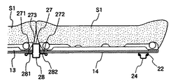
【0020】
ここで、反転前の使用状態では、図8に示すように、各シートクッションパネル13,14の外側縁(一方のみ図示)はアッパレール22上に位置してその荷重が支持される。一方、各シートクッションパネル13,14の内側縁は縦枠27に形成された受けフランジ部281,282上に位置してその荷重が支持される。このように、前後方向へ延びるアッパレール22と縦枠27のフランジ部271,272によって、シートクッションパネル13,14(すなわちシートクッションS1)の荷重は確実に支持される。このように、アッパレール22と縦枠27のフランジ部271,272によってシートクッションS1の荷重を支持するようにしたから、所定の座面高さでシートクッションS1の厚さを十分確保することができる。
【0021】
なお、縦枠27の本体部273に突設した受けフランジ部271,272でシートクッションパネル13,14の内側縁を支持するようにしたから、上記本体部273が既述のように後方へ向けて次第に高くなっていても、これに無関係にシートクッションパネル13,14を所定の高さで保持することができる。このように、縦枠27の本体部273を両シートクッションS1間に配置したから、本体部273の断面積を大きくすることにより、シートクッションS1の厚さに影響をおよぼすことなく、フレーム体2の強度を十分確保することができる。
【0022】
【発明の効果】
以上のように本発明の車両用シートによれば、シートクッションの厚さを十分確保することが可能であるとともに、フレーム体の強度も向上させることができる。
【図面の簡単な説明】
【図1】本発明の一実施形態における、車両シートのフレーム構造を示す全体斜視図である。
【図2】車両シートのフレーム構造の要部斜視図である。
【図3】車両シートのフレーム構造の要部分解斜視図である。
【図4】縦枠の側面図である。
【図5】図4のV−V線に沿った断面図である。
【図6】図4のVI−VI線に沿った断面図である。
【図7】縦枠前端部の斜視図である。
【図8】シートクッション部の垂直断面図である。
【図9】従来の車両用シートの全体側面図である。
【符号の説明】
1…長椅子シート、11,12…シート部、13,14…シートクッションパネル、2…フレーム体、21,22…アッパレール、25…前枠、26…後枠、27…縦辺フレーム、271,272…受けフランジ部、33…ブラケット、38…軸体、S1…シートクッション、S2…シートバック。[0001]
TECHNICAL FIELD OF THE INVENTION
BACKGROUND OF THE INVENTION 1. Field of the Invention The present invention relates to a vehicle seat, and in particular, forms a flat surface that extends forward from a back surface of a seat cushion in which a seat back is tilted forward in a space created by inverting a seat cushion forward. The present invention relates to a so-called double flat type vehicle seat structure which can be improved.
[0002]
[Prior art]
JP-A-10-226253 discloses that, as shown in FIG. 9, the lower surface of the front end of the seat cushion S1 is connected to an upper rail 42 by a hinge 41, and the seat cushion S1 is moved forward about an hinge shaft 43 as shown by an arrow. A vehicular seat is disclosed in which the seat back S2 is tilted up and down and the seat back S2 is tilted forward into the space created at this time so that the luggage compartment floor F can be enlarged. In this vehicle seat, the cross frames 44 and 45 are bridged over the front end and the rear end of the left and right upper rails 42 (only one is shown), and the cross frames 44 and 45 are turned upright. It is provided at a position in contact with the bottom surface of the seat cushion S1 in the previous use state (the state of FIG. 9) to support the load of the seat cushion S1.
[0003]
[Problems to be solved by the invention]
However, in the above-described conventional structure, when the thickness of the seat cushion is sufficiently secured at a predetermined seating surface height, it is not possible to secure a sufficiently large cross section of the cross frames 44 and 45 in terms of space. There is a problem that the strength of the substantially rectangular frame body 4 composed of the cross frames 44 and 45 and the left and right upper rails 42 is not sufficient.
[0004]
Accordingly, the present invention is to solve such a problem, and an object of the present invention is to provide a vehicle seat capable of ensuring a sufficient thickness of a seat cushion and improving the strength of a frame body. And
[0005]
In order to achieve the above object, according to the first aspect of the present invention, two seat cushions (S1) are provided on one frame body (2) provided on a vehicle floor in the vicinity of right and left. In the vehicle seat, the front end of the seat cushion (S1) is pivotally supported on the frame body (2), and the seat cushion (S1) can be flipped up around the front end and rotated. (2) an outer frame, which is substantially rectangular in plan view and includes a front frame (25), a rear frame (26), and left and right side frames (21, 22); (25) and a vertical frame (27) connecting the rear frame (26), the rear frame (26) is arranged behind the seat cushion (S1), and the left and right side edges of the seat cushion (S1). With the side frames (21, 22) and the vertical frame (27) As well as lifting, the vertical frame (27), the side edges of both the seat cushion (S1) main body portion disposed between the (273), projecting laterally from the body portion (273), the seat cushion (S1) And receiving parts (271, 272) on which the components are placed.
[0006]
In the first aspect of the invention, the rear frame is moved from a position where the rear frame is in contact with the conventional seat cushion and receives the load to a rear position of the seat cushion, and the load of the seat cushion is moved to the side frame of the outer frame. Because it is received by the vertical frame provided in the outer frame, the cross section of the rear frame can be made sufficiently large, it is possible to secure sufficient strength of the frame body and make the thickness of the seat cushion sufficient Can be secured. And, since the main body of the vertical frame is arranged between the two seat cushions, by increasing the cross-sectional area of the main body, it is possible to sufficiently secure the strength of the frame body without affecting the thickness of the seat cushion. it can.
[0009]
In the second invention, one shaft member (38) is provided on the bracket (33) provided at the front end of the vertical frame (27), and the front end of each seat cushion (S1) is provided at both ends of the shaft member (38). The inner parts are respectively connected rotatably.
[0010]
In the second aspect of the present invention, since each seat cushion is rotated around a common single shaft member, it is possible to ensure good mounting accuracy of the two in the flipped-up state.
[0011]
In addition, the code | symbol in the said parenthesis shows the correspondence with the concrete means described in embodiment mentioned later.
[0012]
BEST MODE FOR CARRYING OUT THE INVENTION
FIG. 1 shows the frame structure of the chaise lounge seat 1. The couch seat 1 is divided into left and right seat portions 11 and 12 in the longitudinal direction (the left and right direction in FIG. 1) at a ratio of about 6: 4, and a seat cushion S1 is placed on each of the seat portions 11 and 12. There are provided seat cushion panels 13 and 14 for placing, and seat back panels 15 and 16 for holding the seat back S2. Each of the seat back panels 15 and 16 has both lower end portions connected to a frame body 2 to be described later by well-known reclining mechanisms 17, 18, 19 and 20, and can be tilted forward.
[0013]
The details of the frame body 2 are shown in FIG. The frame body 2 is formed in a substantially rectangular shape in plan view by connecting the outer periphery of the seat cushion S1 (FIG. 1) of each of the seat portions 11 and 12, and left and right side frames 21 and 22 are constituted by upper rails of slide rails. ing. Each of the upper rails 21 and 22 is slidable in the front-rear direction (in the diagonal left and right direction in FIG. 2) along the lower rails 23 and 24 provided on the vehicle floor, and the rear ends of the upper rails 21 and 22 are reclined. Lower arms 171 and 201 constituting the mechanisms 17 and 20 are fixed. Upper arms 172 and 202 constituting reclining mechanisms 17 and 20 are rotatably coupled to the lower arms 171 and 201 so as to be rotatable and lockable at predetermined positions, and the respective seat back panels 15 and 16 (FIG. The outer lower end of 1) is fixed. Brackets 31 and 32 are protruded from the front ends of the upper rails 21 and 22, respectively.
[0014]
The front frame 25 and the rear frame 26 of the frame body 2 are each made of a pipe material, and the front frame 25 is bridged between the front ends of the left and right upper rails 21 and 22 to connect them. As shown in FIG. 1, the rear frame 26 is disposed at a position behind the rear edges of the seat cushion panels 13 and 14 and not receiving the load of the seat cushion S1, and the rear ends of the left and right upper rails 21 and 22 are provided. It is erected between brackets 211 and 221 provided in the section, and these are connected. As described above, since the rear frame 26 is provided at a position in contact with the seat cushion S1 as in the related art and away from the position receiving the load, a large-diameter pipe material having sufficient strength is used. Therefore, the strength of the frame body can be sufficiently ensured.
[0015]
A vertical frame 27 is provided on the frame body 2, and the vertical frame 27 extends along the boundary of the seat cushion S <b> 1 (FIG. 1) of the left and right seat portions 11 and 12, and connects the front frame 25 and the rear frame 26. ing. FIG. 4 shows a side view of the vertical frame 27, and FIGS. 5 and 6 show the cross-sectional shapes thereof. The vertical frame 27 has a substantially inverted U-shaped cross section (FIG. 5) in which the front half (the left half in FIG. 4) of the main body 273 opens downward, and both lower ends are bent horizontally to serve as receiving portions. Receiving flange portions 271 and 272. The height of the main body 273 of the vertical frame 27 gradually increases from the front end toward the rear, and in the rear half thereof, a reinforcing plate 28 having a shallow substantially U-shaped cross section is provided with an opening edge flange 281, as shown in FIG. At 282, it is joined to the receiving flange portions 271 and 272 from below to form a closed sectional structure.
[0016]
Lower arms 181 and 191 constituting reclining mechanisms 18 and 19 are fixed to the rear end left and right positions of the vertical frame 27, respectively (FIG. 2), and reclining mechanisms 18 and 19 are formed on each lower arm 181 and 191. The upper arms 182 and 192 are rotatably and lockably connected at predetermined positions, and the lower inner ends of the seat back panels 15 and 16 are fixed to the upper arms 182 and 192 (FIG. 1). Even when a large load is applied to the vertical frame 27 from the seat back panels 15 and 16 via the reclining mechanisms 18 and 19 during rapid acceleration and deceleration of the vehicle, the rear half of the main body 273 of the vertical frame 27 is closed as described above. In addition to the structure, the second half has a cross-sectional shape extending in the up-down direction compared to the first half (see FIGS. 5 and 6), and thus exhibits sufficient durability against the load.
[0017]
At the front end of the vertical frame 27, a bracket 33 is erected (FIG. 3). The bracket 33 has a substantially U-shape in plan view, and is provided with a single shaft member 38 that horizontally penetrates the opposing side walls. Plate-shaped brackets 34, 35, 36, and 37 having mounting holes on both sides of the front end are provided upright on each of the seat cushion panels 13 and 14, and mounting holes for the brackets 35 and 36 provided on the inside of the front end are provided. 351 and 361 are rotatably fitted to both ends of the shaft member 38, respectively (FIG. 7). In addition, a weld nut 342 (only one is shown) is attached to a mounting hole 371 (only one is shown) of each of the brackets 34, 37 (FIG. 3) provided outside the front ends of the respective seat cushion panels 13, 14. Bolts 39 inserted from outside into the mounting holes 311 and 321 of the brackets 31 and 32 provided at the front end of the upper rail 22 are screwed into the weld nut 342.
[0018]
Accordingly, each of the seat cushion panels 13 and 14 on which the seat cushion S1 is placed can be turned forward and backward around a line connecting the shaft member 38 and the bolt 39. At this time, since the left and right seat cushion panels 13 and 14 are inverted around the common shaft member 38, the mounting accuracy of the two in the inverted state is secured. In this case, the overall strength of the bracket 33 is also improved by arranging the shaft member 38 between both side walls of the U-shaped bracket 33 in plan view.
[0019]
In the space created by inverting the seat cushion S1, the reclining mechanisms 17 to 20 move the seat back S2 forward, and a flat surface extending from the back surface of the seat back S2 to the bottom surface of the inverted seat cushion S1. It is formed, and luggage and the like can be loaded on this flat surface.
[0020]
Here, in the use state before inversion, as shown in FIG. 8, the outer edges (only one is shown) of each of the seat cushion panels 13 and 14 are located on the upper rail 22 to support the load. On the other hand, the inner edges of the seat cushion panels 13 and 14 are located on receiving flange portions 281 and 282 formed on the vertical frame 27 to support the load. Thus, the load of the seat cushion panels 13 and 14 (that is, the seat cushion S1) is reliably supported by the upper rail 22 extending in the front-rear direction and the flange portions 271 and 272 of the vertical frame 27. As described above, since the load of the seat cushion S1 is supported by the upper rail 22 and the flange portions 271 and 272 of the vertical frame 27, the thickness of the seat cushion S1 can be sufficiently secured at a predetermined seating surface height. .
[0021]
Since the inner edges of the seat cushion panels 13 and 14 are supported by the receiving flanges 271 and 272 projecting from the main body 273 of the vertical frame 27, the main body 273 is directed rearward as described above. Even if the height is gradually increased, the seat cushion panels 13 and 14 can be held at a predetermined height regardless of this. As described above, since the main body 273 of the vertical frame 27 is disposed between the two seat cushions S1, by increasing the cross-sectional area of the main body 273, the frame body 2 is not affected by the thickness of the seat cushion S1. Can secure sufficient strength.
[0022]
【The invention's effect】
As described above, according to the vehicle seat of the present invention, the thickness of the seat cushion can be sufficiently ensured, and the strength of the frame body can be improved.
[Brief description of the drawings]
FIG. 1 is an overall perspective view showing a frame structure of a vehicle seat according to an embodiment of the present invention.
FIG. 2 is a perspective view of a main part of a frame structure of a vehicle seat.
FIG. 3 is an exploded perspective view of a main part of a frame structure of a vehicle seat.
FIG. 4 is a side view of a vertical frame.
FIG. 5 is a sectional view taken along line VV of FIG.
FIG. 6 is a sectional view taken along the line VI-VI in FIG. 4;
FIG. 7 is a perspective view of a front end of a vertical frame.
FIG. 8 is a vertical sectional view of a seat cushion portion.
FIG. 9 is an overall side view of a conventional vehicle seat.
[Explanation of symbols]
DESCRIPTION OF SYMBOLS 1 ... Chaise seat, 11, 12 ... Seat part, 13, 14 ... Seat cushion panel, 2 ... Frame body, 21, 22 ... Upper rail, 25 ... Front frame, 26 ... Rear frame, 27 ... Vertical frame, 271, 272 ... receiving flange part, 33 ... bracket, 38 ... shaft body, S1 ... seat cushion, S2 ... seat back.