JP3555152B2 - Vehicle vibration reduction device - Google Patents
Vehicle vibration reduction device Download PDFInfo
- Publication number
- JP3555152B2 JP3555152B2 JP30761893A JP30761893A JP3555152B2 JP 3555152 B2 JP3555152 B2 JP 3555152B2 JP 30761893 A JP30761893 A JP 30761893A JP 30761893 A JP30761893 A JP 30761893A JP 3555152 B2 JP3555152 B2 JP 3555152B2
- Authority
- JP
- Japan
- Prior art keywords
- vibration
- actuator
- signal
- electric signal
- engine
- Prior art date
- Legal status (The legal status is an assumption and is not a legal conclusion. Google has not performed a legal analysis and makes no representation as to the accuracy of the status listed.)
- Expired - Fee Related
Links
Images


Landscapes
- Combined Devices Of Dampers And Springs (AREA)
- Vibration Prevention Devices (AREA)
Description
【0001】
【産業上の利用分野】
この発明は、車体上の振動源から車体へ伝達される振動が低減されるようにアクチュエータにて加振力を発生させて車体振動を低減するようにした車両の振動低減装置に関し、特に、アクチュエータの故障状態を防止するフェイルセイフ対策に関する。
【0002】
【従来の技術】
従来より、エンジン等の車両用パワーユニットを車体に支持するための支持装置として、例えば特開昭61−2939号公報に開示されるものでは、車体フレームに対しエンジン等のパワーユニットを支持するように取り付けられ、該車体フレームを、内蔵した加振用の電磁石等で加振することによってパワーユニットから車体フレームに伝達される振動を低減するようになされている。つまり、このものはアクチュエータの機能を有し、このアクチュエータによって車体振動の位相に対して逆位相でかつ同振幅の振動を車体フレームに付与することにより、車両振動を有効に低減するようにしている。
【0003】
【発明が解決しようとする課題】
ところで、上記従来のものでは、電磁石等の作動により加振力を発生するので、その電磁石等に過大な電流が流れたとき等には、その電磁石等が焼き付いてアクチュエータの故障状態となる。このため、振動低減制御を安定して行うには、このアクチュエータの故障状態を未然に防止する対策が必要である。
【0004】
本発明は斯かる点に鑑みてなされたもので、その目的とするところは、上記加振用アクチュエータについての所定の状態をモニタするようにすることにより、アクチュエータが故障状態に陥るのを確実にかつ未然に防止しようとすることにある。
【0005】
【課題を解決するための手段】
上記の目的を達成すべく、この発明では、電磁石等のアクチュエータに出力される電気信号の出力値を常時監視し、この出力値が所定以上に高くなったときを異常状態と見做して、電気信号の出力値自体に規制をかけるようにした。
【0006】
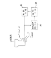
すなわち、図1に示すように、請求項1の発明では、車体1と振動源2との間に配設され、電気信号により加振力を発生するアクチュエータ4と、振動源2から車体1へ伝達される振動が低減されるように電気信号を生成して該電気信号を上記アクチュエータ4に出力する制御手段24とを備えた車両の振動低減装置に対して、上記制御手段24から出力される電気信号の出力値が所定値よりも増大したことを検出する電気信号検出手段28と、この電気信号検出手段28の出力を受け、上記電気信号の出力値が所定値よりも増大したときに、制御手段24から出力される電気信号に規制を加える規制手段29とを設ける。そして、上記電気信号検出手段28は、上記所定値を上記振動源2の振動周波数の増加に応じて大きくするように構成されたものとする。
【0007】
【作用】
上記の構成により、請求項1の発明では、制御手段24において振動源2から車体1へ伝達される振動が低減されるように電気信号が生成されてアクチュエータ4に出力され、この制御手段24からアクチュエータ4に出力される電気信号の出力値が所定値よりも増大したとき、そのことが電気信号検出手段28により検出され、この検出手段28の出力を受けた規制手段29により、制御手段24からアクチュエータ4に出力される電気信号に規制が加えられる。このため、アクチュエータ4に過大な電流が流れてその焼付き等によりアクチュエータ4が故障するのを確実にかつ未然に防止することができる。
【0008】
また、電気信号検出手段28において制御手段24からアクチュエータ4に出力される電気信号の出力値と比較される所定値は、振動源2の振動周波数に基づいて変更されて該振動周波数の増加に応じて大きくなるものであるので、アクチュエータ4の故障状態の判定基準を振動源2の状態に応じて適正に設定し、振動周波数により変化するアクチュエータ4の抵抗値を考慮して所定値を変化させることができ、よって、振動源2の低周波から高周波までの広い振動域で振動低減制御を有効に行いつつ、アクチュエータ4の故障を防止することができる。
【0009】
【実施例】
以下、本発明の実施例を図面に基づいて説明する。図7において、1は車両(図示例では自動車)の車体、2は車体1前部のエンジンルーム3内に配置された振動源としてのエンジンであって、このエンジン2はその下部にて少なくとも1つのエンジンマウント4(1つのみ図示する)を介して車体1のフレーム1aに弾性支持されている。
【0010】
上記各エンジンマウント4は、加振力を発生する本発明でいうアクチュエータを構成するもので、図6に拡大詳示するように、下方に開放された略有底筒状のケーシング4aと、該ケーシング4aの下端内周縁部に固着された略中空錐形状の支持ゴム4bと、該支持ゴム4bの中心孔周面に固着された支持部材4cとを基本構成として備えている。そして、上記ケーシング4aの上端面にはエンジン2の下端部にねじ止めされて締結されるエンジン側挿入ロッド4dが、また支持部材4cの下端面には上記と同様に車体フレーム1aにねじ止めされて締結される車体側挿入ロッド4eがそれぞれ突設されている。
【0011】
また、上記ケーシング4aの下端開口部は支持部材4cを貫通せしめたダイアフラム4fによって液密状に閉塞され、このケーシング4aとダイアフラム4fとによって液室4gが形成され、この液室4g内にオイル等の非圧縮性流体が封入されている。また、この液室4gは、上記支持ゴム4bによってその上側の主液室4hと下側の副液室4iとに上下に区画され、上記主液室4hと副液室4iとの間は支持ゴム4bの側方に形成した小径のオリフィス4jにより連通されていて、主液室4hと副液室4iとの流体がオリフィス4jを介して相互に流通可能となっている。さらに、ケーシング4a内の上部には、主液室4hの上壁面を形成する加振板4kがラバー4mを介して上下移動可能に取り付けられ、該加振板4kの上側には、磁界中の電線に電流を流したときの該電線の受ける磁力により加振板4kを上下に移動させる動電型アクチュエータ5が配設されている。この動電型アクチュエータ5は、ケーシング4aの内部上底面に垂設された永久磁石5aと、ケーシング4aの内部上周面に磁石5aと同心状に取り付けられ、磁路を形成する継鉄5bと、この継鉄5b及び磁石5a間の間隙に配置され、かつ加振板4kに接合された電磁コイル5cとを備えてなり、電磁コイル5cに加振信号を出力することにより、加振板4kを上下に振動させて主液室4hの容積を可変とし、主液室4hと副液室4iとの間で流体をオリフィス4jを通じて流通させることを繰り返して支持ゴム4bを上下に振動させ、エンジン2及び車体1のフレーム1aとの間に上下方向の加振力を発生させるようになされている。
【0012】
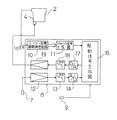
再び、図7において、7は車両の例えば左前輪近傍位置に配置されて車体1の上下加速度を基に車両の振動を検出する加速度センサからなる振動センサであって、該振動センサ7の振動信号はコントローラ8に入力されており、このコントローラ8により、振動センサ7で検出される振動信号(上下加速度信号)に基いてエンジンマウント4を加振制御して車体1の振動を低減する構成となっている。
【0013】
上記コントローラ8のブロック構成を図5に示す。同図において、10はエンジン2の点火信号に基いてエンジン回転の周期を測定するエンジン回転周期測定回路、11は該周期測定回路10にて測定されたエンジン回転の周期に基いてエンジン2の振動に関連するリファレンス信号を生成するリファレンス信号生成器である。12は上記振動センサ7からの振動信号を増幅する増幅器、13は該増幅器12で増幅された振動信号の低周波成分を濾波するローパスフィルタ、14は該ローパスフィルタ13で濾波された振動信号をアナログ値からデジタル値に変換するA/D変換器で、このA/D変換器14から出力される振動信号は、該振動信号に基いて上記エンジンマウント4を加振制御する加振信号としてのアクチュエータ駆動信号(電気信号)を生成する駆動信号生成器16に入力されている。
【0014】
さらに、17は上記駆動信号生成器16にて生成される駆動信号をデジタル値からアナログ値に変換するD/A変換器、18は該D/A変換器17からの駆動信号の低周波成分を濾波するローパスフィルタ、19は該ローパスフィルタ18で濾波された駆動信号を増幅する増幅器であって、該増幅器19で増幅された駆動信号は上記各エンジンマウント4の動電型アクチュエータ5に出力される。
【0015】
また、コントローラ8にはアクセル開度を検出するアクセル開度センサ9からの信号が入力されている。
【0016】
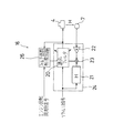
上記駆動信号生成器16は、その駆動信号の生成のアルゴリズムとして、最小自乗法(Least Mean Square Method=LMS)の適応アルゴリズムが用いられる。この最小自乗法の適応アルゴリズムを用いた駆動信号生成器16の内部構成を図4に示す。同図において、20は上記リファレンス信号生成器11により生成されたリファレンス信号の位相及びゲインを調整して所定のアクチュエータ駆動信号を生成するデジタルフィルタからなる適応フィルタ、21はデジタルフィルタで、これは、駆動信号生成器16の駆動信号の出力によりエンジンマウント4が加振されて車両に振動が励起し、この車両振動が振動センサ7で検出されてその振動信号が駆動信号生成器16に入力されるまでの伝達特性Hをモデル化したものである。22は振動センサ7からの振動信号に収束係数α(0<α<1)を乗算する収束係数乗算回路、23はこの収束係数乗算回路22で収束係数αが掛け合わされた振動信号に上記デジタルフィルタ21を通過したリファレンス信号を掛け合わせて、上記適応フィルタ20のフィルタ係数を逐次更新する信号を出力する乗算器である。そして、上記適応フィルタ20、デジタルフィルタ21、収束係数乗算回路22及び乗算器23により制御手段としての制御部24が構成されており、この制御部24により、振動センサ7からの振動信号及び収束係数αに基いて適応フィルタ20のフィルタ係数を更新して駆動信号を適宜調整し、該駆動信号でエンジンマウント4を駆動制御して、その車両に付加する振動の位相及び振幅をエンジン2の振動と逆位相で同振幅とし、車両の振動を低減するようになされている。
【0017】
さらに、駆動信号生成器16には、上記エンジン回転周期測定回路10からのエンジン回転周期信号及び適応フィルタ20から出力される駆動信号をそれぞれ入力して、適応フィルタ20のフィルタ係数を制限するフィルタ係数制限回路26が設けられている。
【0018】
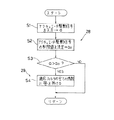
このフィルタ係数制限回路26において行われる信号処理動作の具体例を図2のフローチャート図により説明するに、まず、最初のステップS1で、適応フィルタ20からエンジンマウント4の動電型アクチュエータ5に出力されるアクチュエータ駆動信号の電圧値aを入力し、ステップS2では駆動信号電圧値aの制限値(本発明でいう所定値)をa0 として決定する。この制限値a0 の決定は、エンジン回転周期測定回路10で測定されるエンジン回転周期を基にした振動周波数fに応じて行う。すなわち、アクチュエータ駆動信号に対する制限は電圧値で行われるが、図3に示すように、エンジンマウント4の動電型アクチュエータ5に対する電気抵抗Rはその駆動周波数fに応じて変化するので(尚、図3の電気抵抗R(f)のピークは共振点で、これを避けた範囲Aが使用される)、動電型アクチュエータ5の駆動エネルギーを一定にするためには駆動周波数fに応じて電圧の制限値a0 を変更する必要がある。具体的に、駆動電圧をV、駆動電流をIとすると、駆動エネルギーEは、
E(w)=V×I=V2/R(f)
となる。従って、エネルギー制限値をE0 とすると、
E0 =a02 /R(f)
a0 ={R(f)×E0 }1/2
となり、動電型アクチュエータ5の電気抵抗R(f)に応じた制限値a0 が決定される。そして、図3に示す如く、電気抵抗R(f)は駆動周波数fの増加に応じて増大するので、制限値a0 は駆動周波数f、従ってエンジン2の振動周波数の増加に応じて大きくなるように決定される。
【0019】
上記ステップS2の後はステップS3に進み、駆動信号の電圧値aが制限値a0 よりも大きいか否かを判定する。この判定がa≦a0 のNOのときにはそのままリターンするが、a>a0 のYESのときにはステップS4に進み、適応フィルタ20の全ての係数にa0 /aを掛けた後、リターンする。
【0020】
この実施例では、上記ステップS1〜S3により、上記制御部24からエンジンマウント4の動電型アクチュエータ5に出力される電気信号としての駆動信号の電圧値aが制限値a0 よりも増大したことを検出するようにした電気信号検出手段28が構成されている。
【0021】
また、ステップS4により、上記電気信号検出手段28の出力を受け、動電型アクチュエータ5への駆動信号の電圧値aが制限値a0 よりも増大したときに、適応フィルタ20で最適化演算により演算される全ての係数にa0 /aを掛けて電圧値aを制限値a0 未満の値に規制し、制御部24から動電型アクチュエータ5に出力される駆動信号に規制を加えるようにした規制手段29が構成されている。
【0022】
次に、上記実施例の作用について説明する。エンジン2が運転状態にあるとき、その点火信号がコントローラ8に入力され、そのエンジン回転周期測定回路10でエンジン2の回転周期が計測され、リファレンス信号生成器11において、上記回転周期信号を基にエンジン回転周期に対応したリファレンス信号が生成され、このリファレンス信号は駆動信号生成器16に入力される。駆動信号生成器16では、リファレンス信号の位相及びゲインが適応フィルタ20で調整されて駆動信号が生成され、この駆動信号はD/A変換器17でアナログ信号に変換された後に加振用アクチュエータとしてのエンジンマウント4の動電型アクチュエータ5に出力され、該エンジンマウント4の作動により振動が発生する。
【0023】
また、これと同時に、車体1の上下方向の振動が振動センサ7により検出され、この振動センサ7からの振動信号はA/D変換器14でデジタル信号に変換されて駆動信号生成器16に入力される。この駆動信号生成器16では、入力された振動信号に収束係数乗算回路22で収束係数αが掛け合わされ、次いでデジタルフィルタ21を通過したリファレンス信号と乗算器23において掛け合わされる。そして、この乗算器23の出力信号により、上記振動センサ7にて検出される振動信号の自乗和が最小になるようにLMSアルゴリズムにより上記適応フィルタ20のフィルタ係数が逐次更新され、この適応フィルタ20のフィルタ係数の更新により振動信号が低減されるようにリファレンス信号の位相及びゲインが逐次調整されて最適化される。このことで、エンジンマウント4により発生した振動は振動センサ7の位置でエンジン2からの振動と互いに打ち消し合って、該振動センサ7で検出される車体1の振動を低減でき、エンジン2の上下振動が発生していても車体1が振動するのを有効に防止することができる。
【0024】
そして、上記コントローラ8では、その駆動信号生成器16のフィルタ係数制限回路26において、適応フィルタ20から動電型アクチュエータ5に出力されるアクチュエータ駆動信号の電圧値aとその制限値a0 との大小が常時比較され、駆動信号の電圧値aが制限値a0 以下のときに上記の制御が行われる。
【0025】
これに対し、アクチュエータ駆動信号の電圧値aが制限値a0 よりも大きいときには、適応フィルタ20の全ての係数にa0 /aが掛けられ、適応フィルタ20で最適化演算により演算される駆動信号の電圧値aが全て制限値a0 未満の値に規制される。この駆動信号の規制の結果、動電型アクチュエータ5に過大な電流が流れてその焼付き等によりエンジンマウント4が故障するのを確実にかつ未然に防止することができる。
【0026】
その場合、上記フィルタ係数制限回路26においてアクチュエータ駆動信号の電圧値aと比較される制限値a0 は、エンジン2の回転周期に対応した振動周波数に基づいて変更されるため、エンジンマウント4の故障状態の判定基準をエンジン2の運転状態に応じて適正に設定でき、図3に示す如く、動電型アクチュエータ5の駆動周波数f、つまりエンジン2の振動周波数により変化する動電型アクチュエータ5の抵抗値R(f)を考慮して電圧値aの制限値a0 を変化させることができ、エンジン2の低周波から高周波までの広い振動域、換言するとエンジン2の低回転域から高回転域までの広い回転域で振動低減制御を有効に行いつつ、エンジンマウント4の故障を防止することができる。
【0027】
尚、上記実施例では、アクチュエータを動型アクチュエータとしているが、その他、電磁石に電流を流して該電磁石の発生する磁力を利用する電磁型アクチュエータを採用することもできる。
【0028】
また、上記実施例では、エンジン2を車体1に支持するエンジンマウント4をアクチュエータとした場合であるが、本発明は、車両における他の振動源、例えば変速機等の振動を、動電型アクチュエータを持ったアクチュエータの加振力により低減する場合にも適用することができる。
【0029】
【発明の効果】
以上説明したように、請求項1の発明によると、車体と振動源との間に、電気信号により加振力を発生するアクチュエータを設け、制御手段において、振動源から車体へ伝達される振動が低減されるよう、電気信号を生成して上記アクチュエータに出力するようにした車両の振動低減装置において、アクチュエータに出力される電気信号の出力値が所定値よりも増大したことを検出手段で検出し、このときには、出力される電気信号に規制を加えるとともに、その所定値を振動源の振動周波数の増加に応じて大に変更するようにしたことにより、振動周波数により変化するアクチュエータの抵抗値を考慮して所定値を変化 させ、振動源の低周波から高周波までの広い振動域で振動低減制御を有効に行いつつ、焼付き等によりアクチュエータが故障するのを確実にかつ未然に防止でき、振動低減制御を安定して行うことができる。
【図面の簡単な説明】
【図1】本発明の構成図である。
【図2】本発明の実施例においてフィルタ係数制限器で行われる信号処理動作を示すフローチャート図である。
【図3】動電型アクチュエータの駆動周波数に応じて変化する電気抵抗値の特性を示す特性図である。
【図4】駆動信号生成器の構成を示すブロック図である。
【図5】コントローラのブロック図である。
【図6】マウントの拡大縦断面図である。
【図7】本発明の実施例の全体構成図である。
【符号の説明】
1 車体
2 エンジン(振動源)
4 エンジンマウント
5 動電型アクチュエータ
7 振動センサ
8 コントローラ
16 駆動信号生成器
20 適応フィルタ
24 制御部(制御手段)
26 フィルタ係数制限回路
28 電気信号検出手段
29 規制手段
a アクチュエータ駆動信号の電圧値(電気信号の出力値)
a0 制限値(所定値)[0001]
[Industrial applications]
The present invention relates to a vibration reduction device for a vehicle in which an excitation force is generated by an actuator so that vibration transmitted from a vibration source on the vehicle body to the vehicle body is reduced, and the vehicle body vibration is reduced. The present invention relates to fail-safe measures for preventing a failure state of a vehicle.
[0002]
[Prior art]
2. Description of the Related Art Conventionally, as a support device for supporting a vehicle power unit such as an engine on a vehicle body, for example, in a device disclosed in Japanese Patent Application Laid-Open No. 61-2939, a power unit such as an engine is mounted on a vehicle body frame so as to be supported. The vibration transmitted from the power unit to the vehicle body frame is reduced by vibrating the vehicle body frame with a built-in electromagnet for vibration or the like. In other words, this device has the function of an actuator, and the actuator applies vibration to the vehicle body frame in the opposite phase and the same amplitude to the phase of the vehicle body vibration, thereby effectively reducing the vehicle vibration. .
[0003]
[Problems to be solved by the invention]
By the way, in the above-mentioned conventional device, since an exciting force is generated by the operation of the electromagnet or the like, when an excessive current flows through the electromagnet or the like, the electromagnet or the like is seized and the actuator is in a failure state. For this reason, in order to stably perform the vibration reduction control, it is necessary to take measures to prevent the failure state of the actuator beforehand.
[0004]
The present invention has been made in view of such a point, and an object of the present invention is to monitor a predetermined state of the vibrating actuator so as to ensure that the actuator falls into a failure state. And trying to prevent it beforehand.
[0005]
[Means for Solving the Problems]
In order to achieve the above object, in the present invention, the output value of an electric signal output to an actuator such as an electromagnet is constantly monitored, and when this output value becomes higher than a predetermined value, it is regarded as an abnormal state. The output value of the electric signal itself is regulated.
[0006]
That is, as shown in FIG. 1, in the invention of claim 1, an
[0007]
[Action]
With the above configuration, in the first aspect of the present invention, the control means 24 generates an electric signal so as to reduce the vibration transmitted from the
[0008]
The predetermined value to be compared with the output value of the electric signal output from the control means 24 to the
[0009]
【Example】
Hereinafter, embodiments of the present invention will be described with reference to the drawings. 7 , reference numeral 1 denotes a vehicle body of a vehicle (an automobile in the illustrated example), and 2 denotes an engine serving as a vibration source disposed in an engine room 3 at a front portion of the vehicle body 1. The
[0010]
Each of the
[0011]
A lower end opening of the
[0012]
Referring again to FIG. 7 ,
[0013]
FIG. 5 shows a block configuration of the
[0014]
Further, 17 is a D / A converter for converting the drive signal generated by the
[0015]
Further, a signal from an
[0016]
The driving
[0017]
Further, the
[0018]
A specific example of the signal processing operation performed in the filter
E (w) = V × I = V 2 / R (f)
It becomes. Therefore, if the energy limit value is E0,
E0 = a0 2 / R (f )
a0 = {R (f) × E0} 1/2
The limit value a0 according to the electric resistance R (f) of the
[0019]
After step S2, the process proceeds to step S3, where it is determined whether the voltage value a of the drive signal is larger than the limit value a0. When this determination is NO for a≤a0, the process returns as it is, but when a> a0, for YES, the process proceeds to step S4, where all the coefficients of the adaptive filter 20 are multiplied by a0 / a, and then the process returns.
[0020]
In this embodiment, the fact that the voltage value a of the drive signal as the electric signal output from the
[0021]
In step S4, when the voltage value a of the drive signal to the
[0022]
Next, the operation of the above embodiment will be described. When the
[0023]
At the same time, vibration in the vertical direction of the vehicle body 1 is detected by the
[0024]
In the
[0025]
On the other hand, when the voltage value a of the actuator drive signal is larger than the limit value a0, all the coefficients of the adaptive filter 20 are multiplied by a0 / a. All values a are restricted to values less than the limit value a0. As a result of the regulation of the drive signal, it is possible to reliably and in advance prevent the
[0026]
In this case, the limit value a0 compared with the voltage value a of the actuator drive signal in the filter
[0027]
In the above embodiment, although the actuators and dynamic actuator, other, may be employed an electromagnetic actuator that utilizes magnetic force generated in the electromagnet to by applying a current to the electromagnet.
[0028]
Further, in the above embodiment, the
[0029]
【The invention's effect】
As described above, according to the first aspect of the present invention, an actuator that generates an exciting force by an electric signal is provided between the vehicle body and the vibration source, and the control unit controls the vibration transmitted from the vibration source to the vehicle body. In a vehicle vibration reduction device configured to generate an electric signal and output the generated electric signal to the actuator, the detection unit detects that an output value of the electric signal output to the actuator has exceeded a predetermined value. in this case, with added constraints on the electrical signal output, by which is adapted to change the large in accordance with the predetermined value to increase the vibration frequency of the vibration source, considering the resistance value of the actuator which varies the oscillation frequency changing the predetermined value and, while effectively perform vibration reduction control in a wide oscillation range up high frequency from the low frequency of the vibration source, the actuator by seizing Can be prevented to reliably and advance from being disabled, it is possible to stably perform vibration reduction control.
[Brief description of the drawings]
FIG. 1 is a configuration diagram of the present invention.
FIG. 2 is a flowchart illustrating a signal processing operation performed by a filter coefficient limiter in the embodiment of the present invention.
FIG. 3 is a characteristic diagram illustrating characteristics of an electric resistance value that changes according to a driving frequency of an electrodynamic actuator.
FIG. 4 is a block diagram illustrating a configuration of a drive signal generator.
FIG. 5 is a block diagram of a controller.
FIG. 6 is an enlarged vertical sectional view of a mount.
FIG. 7 is an overall configuration diagram of an embodiment of the present invention.
[Explanation of symbols]
1
4
26 Filter
a0 Limit value (predetermined value)
Claims (1)
振動源から車体へ伝達される振動が低減されるように電気信号を生成して上記アクチュエータに出力する制御手段とを備えた車両の振動低減装置において、
上記制御手段から出力される電気信号の出力値が所定値よりも増大したことを検出する電気信号検出手段と、
上記電気信号検出手段の出力を受け、上記電気信号の出力値が所定値よりも増大したときに、制御手段から出力される電気信号に規制を加える規制手段とを備え、
上記電気信号検出手段は、上記所定値を上記振動源の振動周波数の増加に応じて大きくするように構成されていることを特徴とする車両の振動低減装置。An actuator that is disposed between the vehicle body and the vibration source and generates an exciting force by an electric signal;
Control means for generating an electric signal so as to reduce the vibration transmitted from the vibration source to the vehicle body and outputting the generated electric signal to the actuator ,
Electric signal detection means for detecting that the output value of the electric signal output from the control means has increased beyond a predetermined value,
Receiving the output of the electric signal detection means, when the output value of the electric signal is greater than a predetermined value, comprising a restriction means for restricting the electric signal output from the control means ,
A vibration reduction device for a vehicle, wherein the electric signal detection means is configured to increase the predetermined value in accordance with an increase in a vibration frequency of the vibration source .
Priority Applications (1)
| Application Number | Priority Date | Filing Date | Title |
|---|---|---|---|
| JP30761893A JP3555152B2 (en) | 1993-12-08 | 1993-12-08 | Vehicle vibration reduction device |
Applications Claiming Priority (1)
| Application Number | Priority Date | Filing Date | Title |
|---|---|---|---|
| JP30761893A JP3555152B2 (en) | 1993-12-08 | 1993-12-08 | Vehicle vibration reduction device |
Publications (2)
| Publication Number | Publication Date |
|---|---|
| JPH07158691A JPH07158691A (en) | 1995-06-20 |
| JP3555152B2 true JP3555152B2 (en) | 2004-08-18 |
Family
ID=17971203
Family Applications (1)
| Application Number | Title | Priority Date | Filing Date |
|---|---|---|---|
| JP30761893A Expired - Fee Related JP3555152B2 (en) | 1993-12-08 | 1993-12-08 | Vehicle vibration reduction device |
Country Status (1)
| Country | Link |
|---|---|
| JP (1) | JP3555152B2 (en) |
Families Citing this family (7)
| Publication number | Priority date | Publication date | Assignee | Title |
|---|---|---|---|---|
| JP3695058B2 (en) * | 1997-05-09 | 2005-09-14 | 日産自動車株式会社 | Active vibration control device |
| JP3695061B2 (en) * | 1997-05-15 | 2005-09-14 | 日産自動車株式会社 | Active vibration control device |
| JP3593886B2 (en) * | 1998-06-17 | 2004-11-24 | 日産自動車株式会社 | Active vibration control device for vehicles |
| JP4615879B2 (en) * | 2004-03-02 | 2011-01-19 | 本田技研工業株式会社 | Active anti-vibration support device |
| JP2005249012A (en) * | 2004-03-02 | 2005-09-15 | Honda Motor Co Ltd | Active vibration isolation support device and cylinder deactivation engine control device |
| JP4832808B2 (en) * | 2004-12-28 | 2011-12-07 | 東海ゴム工業株式会社 | Active vibration isolator |
| JP2020106078A (en) * | 2018-12-27 | 2020-07-09 | 本田技研工業株式会社 | Device for damping plate-like member |
-
1993
- 1993-12-08 JP JP30761893A patent/JP3555152B2/en not_active Expired - Fee Related
Also Published As
| Publication number | Publication date |
|---|---|
| JPH07158691A (en) | 1995-06-20 |
Similar Documents
| Publication | Publication Date | Title |
|---|---|---|
| JP3952584B2 (en) | Active vibration isolator | |
| CN101438078B (en) | Damper for automobiles for reducing vibration of automobile body | |
| US5905317A (en) | Vibration insulating device | |
| US5802184A (en) | Active noise and vibration control system | |
| WO2009139424A1 (en) | Vibration control device and vehicle | |
| US5154403A (en) | Power plant suspension device | |
| JP3555152B2 (en) | Vehicle vibration reduction device | |
| JP5098796B2 (en) | Vibration control device and vehicle | |
| JPH05231469A (en) | Anti-vibration support device | |
| Li et al. | Control of loudspeakers using disturbance-observer-type velocity estimation | |
| JP3296606B2 (en) | Power unit mounting device | |
| JP3551653B2 (en) | Active noise and vibration control device | |
| JP4025971B2 (en) | Electric motor control device and gain setting method thereof | |
| JP2003150250A (en) | Vibration suppressing device | |
| JP3366089B2 (en) | Vehicle vibration reduction device | |
| JP3124382B2 (en) | Vehicle vibration reduction device | |
| JP3829408B2 (en) | Active vibration control device for vehicle | |
| JP3163900B2 (en) | Anti-vibration support device | |
| JPH11338553A (en) | Active vibration control device and active noise control device | |
| JP3747619B2 (en) | Active vibration control device | |
| JPH0633980A (en) | Vibration reduction device of vehicle | |
| JP2013061001A (en) | Active vibration isolator | |
| JP3473293B2 (en) | Active vibration control device | |
| JPH09273589A (en) | Vibration noise control device | |
| JP3890673B2 (en) | Self-excited vibration type vibration device |
Legal Events
| Date | Code | Title | Description |
|---|---|---|---|
| A131 | Notification of reasons for refusal |
Free format text: JAPANESE INTERMEDIATE CODE: A131 Effective date: 20040120 |
|
| A521 | Written amendment |
Effective date: 20040317 Free format text: JAPANESE INTERMEDIATE CODE: A523 |
|
| TRDD | Decision of grant or rejection written | ||
| A01 | Written decision to grant a patent or to grant a registration (utility model) |
Effective date: 20040420 Free format text: JAPANESE INTERMEDIATE CODE: A01 |
|
| A61 | First payment of annual fees (during grant procedure) |
Effective date: 20040503 Free format text: JAPANESE INTERMEDIATE CODE: A61 |
|
| R150 | Certificate of patent (=grant) or registration of utility model |
Free format text: JAPANESE INTERMEDIATE CODE: R150 |
|
| LAPS | Cancellation because of no payment of annual fees |