JP3554875B2 - Laser recording device - Google Patents
Laser recording device Download PDFInfo
- Publication number
- JP3554875B2 JP3554875B2 JP439196A JP439196A JP3554875B2 JP 3554875 B2 JP3554875 B2 JP 3554875B2 JP 439196 A JP439196 A JP 439196A JP 439196 A JP439196 A JP 439196A JP 3554875 B2 JP3554875 B2 JP 3554875B2
- Authority
- JP
- Japan
- Prior art keywords
- laser beam
- optical system
- laser
- drum
- recording medium
- Prior art date
- Legal status (The legal status is an assumption and is not a legal conclusion. Google has not performed a legal analysis and makes no representation as to the accuracy of the status listed.)
- Expired - Fee Related
Links
- 230000003287 optical effect Effects 0.000 claims description 33
- 238000003384 imaging method Methods 0.000 claims description 9
- 239000000463 material Substances 0.000 description 8
- 238000001514 detection method Methods 0.000 description 5
- 230000006866 deterioration Effects 0.000 description 4
- 230000000694 effects Effects 0.000 description 2
- 239000012788 optical film Substances 0.000 description 2
- 239000004065 semiconductor Substances 0.000 description 2
- 239000000758 substrate Substances 0.000 description 2
- 238000010586 diagram Methods 0.000 description 1
Images

Landscapes
- Laser Beam Printer (AREA)
Description
【0001】
【発明の属する技術分野】
本発明は、画像信号に対応して変調されたレーザ光線を感光記録媒体である光学フィルムなどの感材上に照射記録するレーザ記録装置に係り、特にレーザ光線の光量変化を検出補正して一定した光量を照射するレーザ記録装置に関する。
【0002】
【従来の技術】
近年、画像情報を記録するための光学記録装置として、半導体レーザを利用したレーザ記録装置が普及している。このようなレーザ記録装置は、画像信号に基づいて変調されたレーザ光線を偏向走査して感光記録媒体の記録面上に結像させる光学走査系を備えた構成になっている。光学走査系は、レーザ光線を照射する光源、例えば半導体レーザ素子と、この光源から出射されるレーザ光線を偏向するミラーと、集光レンズとを備え、レーザ光線は感光記録媒体の記録面上を走査し、その表面で結像するように構成されている。
【0003】
また、従来のレーザ記録装置には、走査中の温度変化や振動などによって生じる結像状態の劣化、例えば、照射光量のムラや焦点の距離のズレなどを自動的に検出して補正する補正手段が備えられているものがある。この種の補正手段を備えたレーザ記録装置として、例えば、特開昭63―8668号公報、あるいは特開平3―81721号公報に記載されたものが知られている。
【0004】
上記公報記載のレーザ記録装置では、光源は固定された状態で配設されており、ドラム表面上に固定されて置かれた感光記録媒体の記録面上へのレーザ光線の走査は、感光記録媒体を固定するドラムそのものの縦横方向への水平移動で行われている。このような走査手段を備えた従来のレーザ記録装置、すなわちドラム移動光学系固定方式のレーザ記録装置では、感光記録媒体が大型化するにつれ、走査の伴うドラムの移動のために大きな空間が必要になる。
【0005】
これに対し、感光記録媒体の横方向の走査(以下、主走査)を回転ミラー、例えばポリゴンミラー、などを回転させてレーザ光線を反射偏向させることによって行い、感光記録媒体の縦方向の走査(以下、副走査)をドラムの縦方向への移動によって行う、ドラム固定光学系移動方式のレーザ記録装置がある。この方式のレーザ記録装置によれば、主走査の方向の空間が節約できるので、装置の小型化を図ることができる。
【0006】
【発明が解決しようとする課題】
しかし、ドラム固定光学系移動方式のレーザ記録装置にあっても、既述した感光記録媒体の記録面上におけるレーザ光線の結像状態の劣化に対する補正手段に関して下記の問題が残されていた。
【0007】
つまり、従来の補正手段では、結像状態を検知するセンサはドラムに固定されており、光学系の移動手段とは独立になっている。さらに、劣化したレーザ光線の結像状態の補正は、センサによって検知された前回副走査直後の結像状態の情報に基づいて行なわれ、その後に続く副走査に備えている。そのため、各副走査の時間において生ずる結像状態の劣化をその副走査の最中においては補正を行なうことができなかった。
【0008】
そこで本発明の課題は、レーザ光線の結像状態の劣化に対する補正手段を改良し、一定濃度で忠実に画像を再現できる、小型のレーザ記録装置を提供することにある。
【0009】
【課題を解決するための手段】
上記課題を解決する本発明のレーザ記録装置は、レーザ光線を照射結像させる光学系と、その表面上に置かれる感光記録媒体の記録面が前記光学系を指向するドラムと、前記感光記録媒体の記録面と非接触の状態にあり、前記光学系から前記記録面への距離と等距離の部位に配置され、前記感光記録媒体の記録面におけるレーザ光の結像状態を検知するセンサとを備えてなり、前記ドラムが固定され、前記光学系が移動することにより、前記レーザ光線が該ドラム表面上に置かれた前記感光記録媒体の記録面を走査するとともに、前記センサが前記光学系の移動に追随するように構成されている。
【0010】
本発明では、センサが光量を検知するものである場合、前記レーザ光線の光量検出値に基づいて前記レーザ光線の出力光量を補正する手段をさらに備える。
【0012】
【発明の実施の形態】
以下、図面を参照して本発明の実施の形態を詳細に説明する。
【0013】
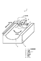
図1は、本発明の一実施形態に係るレーザ記録装置の要部斜視図である。
【0014】
このレーザ記録装置1は、光学系2と、円筒内側面形状の表面を有するドラム8と、から構成されている。ドラム8の表面は光学系2を指向しており、該表面には、感光記録媒体である光学フィルムなどの感材7が置かれている。
【0015】
光学系2は、レーザ光線を出力する光源3と、光源3から出力されたレーザ光線を感材7上で主走査方向に走査させるための回転ミラー4とを備えている。光源3と回転ミラー4は、ともに一つの基板9上に配設されており、走査中において、光源3と回転ミラー4との間隔距離が一定に保たれながら副走査の方向に同時に移動できるように構成されている。
【0016】
なお、図示されていないが、光学系2は、光源3から出力されたレーザ光線を感材7上で結像させるための集光レンズを備えていてもよい。また、副走査を光源3を固定して回転ミラー4だけを副走査の方向に移動させて行う光学系2の構成も可能である。
【0017】
センサ5は、光学系2の移動に追随できるように、光学系2に固定されて配設されているが、感材7とドラム8とは非接触の状態になっており、さらに、結像状態を検知できるように、結像面と光学系2との距離と等距離分、光学系2から離されて配設されている。センサ5は、例えばここでは受光センサであって、結像面におけるレーザ光線の光量を検知するものである。
【0018】
感材7の記録面を走査する走査手段は、横方向の走査である主走査と縦方向の走査である副走査から成る。主走査は、光源3から出射したレーザ光線を回転している回転ミラー4によって反射偏向して行う。また、副走査は、縦方向への光学系2全体の移動により行う。
【0019】
次に、レーザ光線の出力光量の補正手段について説明する。
【0020】
図2は、本実施形態における出力光量の補正手段の構成を簡単に図示したものである。光源3を出射したレーザ光線は、回転している回転ミラー4により反射偏向させられて主走査方向に走査する。この主走査において、レーザ光線は感材7上を走査するとともに、センサ5をも走査する。センサ5は、このとき、照射結像したレーザ光線の光量に対応したレベルの検出信号を出力する。このように出力されたセンサ5からの出力信号はAGC回路(Automatic Gain Control)を含む制御部6に入力される。
【0021】
次に、制御部6の動作を説明する。
【0022】
制御部6は、あらかじめ規定された規定レベルよりレーザ光線の光量が多く、そのため検出信号のレベルが規定レベルを越えた場合、規定レベルと検出信号のレベルの差分から減量すべき光量を算出してレーザ光線の出力を下げて補正するための制御信号を光源3に出力する。逆に、レーザ光線の光量が少なく、そのため検出信号のレベルが規定レベルに満たない場合、規定レベルと検出信号のレベルの差分から増量すべき光量を算出してレーザ光線の出力を上げて補正するための制御信号を光源3に出力する。
【0023】
このように、前回の主走査において変化したレーザ光線の出力を補正し、今回の主走査において再び規定された光量を照射することができる。このようにすれば、光学系2が副走査の方向に移動している最中であっても、主走査毎に光量について光学系2を補正を行うことができ、照射光量について安定したレーザ光線を出射させることが可能となる。
【0024】
なお、上記実施形態において、センサ5は光量を検知するものに限る必要はない。つまりセンサ5は、結像状態を表すパラメータを検知できるものであればよい。こうしたパラメータは、光量のみならず、他に例えば焦点距離などがある。
【0025】
【発明の効果】
以上の説明から明らかなように、本発明のレーザ記録装置によれば、ドラムを固定し、光学系が移動することで感光記録媒体の記録面上でレーザ光線が走査結像する仕組みなので、装置を大型化する必要がなくなるという効果がある。
【0026】
さらに、本発明のレーザ記録装置では、感光記録媒体の記録面付近におけるレーザ光線の光量を検知し、その検知情報に基づいてレーザ光線の出力光量を補正するため、記録濃度を安定に保ち、忠実な記録の再現を行うことができる。
【図面の簡単な説明】
【図1】本発明の一実施形態に係るレーザ記録装置の要部を表す斜視図。
【図2】本実施形態におけるレーザ光線の出力光量の補正手段の概要を示す説明図。
【符号の説明】
1 レーザ記録装置
2 光学系
3 光源
4 回転ミラー
5 センサ
6 制御部
7 感材
8 ドラム
9 基板[0001]
TECHNICAL FIELD OF THE INVENTION
The present invention relates to a laser recording apparatus that irradiates and records a laser beam modulated in accordance with an image signal onto a photosensitive material such as an optical film as a photosensitive recording medium, and in particular, detects and corrects a change in the light amount of the laser beam to be constant. The present invention relates to a laser recording device that irradiates a given light amount.
[0002]
[Prior art]
In recent years, as an optical recording device for recording image information, a laser recording device using a semiconductor laser has become widespread. Such a laser recording apparatus is provided with an optical scanning system for deflecting and scanning a laser beam modulated based on an image signal to form an image on a recording surface of a photosensitive recording medium. The optical scanning system includes a light source that irradiates a laser beam, for example, a semiconductor laser element, a mirror that deflects the laser beam emitted from the light source, and a condenser lens, and the laser beam travels on the recording surface of the photosensitive recording medium. It is configured to scan and image on its surface.
[0003]
Further, a conventional laser recording apparatus includes a correction unit that automatically detects and corrects deterioration of an imaging state caused by temperature change or vibration during scanning, for example, unevenness of irradiation light amount or deviation of focal distance. Some are provided. As a laser recording apparatus provided with this type of correction means, for example, those described in JP-A-63-8668 or JP-A-3-81721 are known.
[0004]
In the laser recording apparatus described in the above publication, the light source is disposed in a fixed state, and the scanning of the laser beam on the recording surface of the photosensitive recording medium fixed and placed on the drum surface is performed by the photosensitive recording medium. Is carried out by horizontal movement of the drum itself in the vertical and horizontal directions. In a conventional laser recording apparatus equipped with such a scanning means, that is, a laser recording apparatus with a fixed drum moving optical system, as the photosensitive recording medium becomes larger, a large space is required for moving the drum accompanying scanning. Become.
[0005]
On the other hand, the scanning in the horizontal direction (hereinafter, main scanning) of the photosensitive recording medium is performed by rotating a rotating mirror, for example, a polygon mirror, to reflect and deflect the laser beam, thereby scanning the photosensitive recording medium in the vertical direction (hereinafter, main scanning). Hereinafter, there is a laser recording apparatus of a drum fixed optical system moving type, which performs (sub-scanning) by moving the drum in the vertical direction. According to the laser recording apparatus of this system, the space in the main scanning direction can be saved, so that the apparatus can be downsized.
[0006]
[Problems to be solved by the invention]
However, even in the laser recording apparatus of the drum fixed optical system moving system, the following problem remains with respect to the means for correcting the deterioration of the imaging state of the laser beam on the recording surface of the photosensitive recording medium described above.
[0007]
That is, in the conventional correction means, the sensor for detecting the imaging state is fixed to the drum, and is independent of the moving means of the optical system. Further, the correction of the image forming state of the deteriorated laser beam is performed based on information of the image forming state immediately after the previous sub-scan detected by the sensor, and is prepared for the subsequent sub-scan. For this reason, it is not possible to correct the deterioration of the imaging state occurring at the time of each sub-scan during the sub-scan.
[0008]
SUMMARY OF THE INVENTION It is an object of the present invention to provide a small-sized laser recording apparatus capable of improving the correction means for the deterioration of the imaging state of a laser beam and reproducing an image with a constant density.
[0009]
[Means for Solving the Problems]
A laser recording apparatus according to the present invention that solves the above-mentioned problems includes an optical system that irradiates and forms an image with a laser beam, a drum on which a recording surface of a photosensitive recording medium is directed to the optical system, and a photosensitive recording medium. A sensor that is in a non-contact state with the recording surface of the optical recording medium, is disposed at a position equidistant from the optical system to the recording surface, and detects an imaging state of laser light on the recording surface of the photosensitive recording medium. When the drum is fixed and the optical system moves, the laser beam scans the recording surface of the photosensitive recording medium placed on the surface of the drum, and the sensor controls the optical system. It is configured to follow the movement.
[0010]
In the present invention, when the sensor detects the light amount, the apparatus further includes a unit for correcting the output light amount of the laser beam based on the detected light amount of the laser beam.
[0012]
BEST MODE FOR CARRYING OUT THE INVENTION
Hereinafter, embodiments of the present invention will be described in detail with reference to the drawings.
[0013]
FIG. 1 is a perspective view of a main part of a laser recording apparatus according to one embodiment of the present invention.
[0014]
The laser recording apparatus 1 includes an optical system 2 and a drum 8 having a cylindrical inner surface. The surface of the drum 8 faces the optical system 2, and a photosensitive material 7 such as an optical film as a photosensitive recording medium is placed on the surface.
[0015]
The optical system 2 includes a
[0016]
Although not shown, the optical system 2 may include a condenser lens for forming an image of the laser beam output from the
[0017]
The sensor 5 is fixed to the optical system 2 so as to be able to follow the movement of the optical system 2, but the photosensitive material 7 and the drum 8 are in a non-contact state. In order to detect the state, the optical system 2 is provided at a distance equal to the distance between the image forming surface and the optical system 2 and separated from the optical system 2. The sensor 5 is, for example, a light receiving sensor here, and detects the light amount of the laser beam on the imaging surface.
[0018]
Scanning means for scanning the recording surface of the photosensitive material 7 includes a main scan which is a horizontal scan and a sub-scan which is a vertical scan. The main scanning is performed by reflecting and deflecting the laser beam emitted from the
[0019]
Next, a means for correcting the output light amount of the laser beam will be described.
[0020]
FIG. 2 is a simplified illustration of the configuration of the output light amount correcting means in the present embodiment. The laser beam emitted from the
[0021]
Next, the operation of the
[0022]
The
[0023]
In this manner, the output of the laser beam changed in the previous main scan can be corrected, and the prescribed amount of light can be irradiated again in the current main scan. In this way, even when the optical system 2 is moving in the sub-scanning direction, the optical system 2 can be corrected for the light amount for each main scan, and the laser beam can be stabilized for the irradiation light amount. Can be emitted.
[0024]
Note that, in the above embodiment, the sensor 5 does not need to be limited to a sensor that detects the amount of light. That is, the sensor 5 only needs to be able to detect a parameter indicating the imaging state. Such parameters include not only the light amount but also, for example, the focal length.
[0025]
【The invention's effect】
As is apparent from the above description, according to the laser recording apparatus of the present invention, since the drum is fixed and the optical system moves, the laser beam scans and forms an image on the recording surface of the photosensitive recording medium. There is an effect that it is not necessary to increase the size of the device.
[0026]
Further, in the laser recording apparatus of the present invention, the light intensity of the laser beam near the recording surface of the photosensitive recording medium is detected, and the output light intensity of the laser beam is corrected based on the detected information. Recording can be reproduced.
[Brief description of the drawings]
FIG. 1 is a perspective view illustrating a main part of a laser recording apparatus according to an embodiment of the present invention.
FIG. 2 is an explanatory diagram illustrating an outline of a correction unit of an output light amount of a laser beam in the embodiment.
[Explanation of symbols]
DESCRIPTION OF SYMBOLS 1 Laser recording device 2
Claims (2)
前記感光記録媒体の記録面と非接触の状態にあり、前記光学系から前記記録面への距離と等距離の部位に配置され、前記感光記録媒体の記録面におけるレーザ光の結像状態を検知するセンサとを備えてなり、
前記ドラムが固定され、前記光学系が移動することにより、前記レーザ光線が該ドラム表面上に置かれた前記感光記録媒体の記録面を走査するとともに、前記センサが前記光学系の移動に追随するように構成されたことを特徴とするレーザ記録装置。An optical system that irradiates and forms an image with a laser beam, and a drum in which a recording surface of a photosensitive recording medium placed on the surface faces the optical system,
It is in a non-contact state with the recording surface of the photosensitive recording medium, is disposed at a position equidistant from the optical system to the recording surface, and detects an imaging state of laser light on the recording surface of the photosensitive recording medium. And a sensor that performs
When the drum is fixed and the optical system moves, the laser beam scans the recording surface of the photosensitive recording medium placed on the surface of the drum, and the sensor follows the movement of the optical system. A laser recording apparatus characterized by being configured as described above.
Priority Applications (1)
| Application Number | Priority Date | Filing Date | Title |
|---|---|---|---|
| JP439196A JP3554875B2 (en) | 1996-01-12 | 1996-01-12 | Laser recording device |
Applications Claiming Priority (1)
| Application Number | Priority Date | Filing Date | Title |
|---|---|---|---|
| JP439196A JP3554875B2 (en) | 1996-01-12 | 1996-01-12 | Laser recording device |
Publications (2)
| Publication Number | Publication Date |
|---|---|
| JPH09193448A JPH09193448A (en) | 1997-07-29 |
| JP3554875B2 true JP3554875B2 (en) | 2004-08-18 |
Family
ID=11583064
Family Applications (1)
| Application Number | Title | Priority Date | Filing Date |
|---|---|---|---|
| JP439196A Expired - Fee Related JP3554875B2 (en) | 1996-01-12 | 1996-01-12 | Laser recording device |
Country Status (1)
| Country | Link |
|---|---|
| JP (1) | JP3554875B2 (en) |
-
1996
- 1996-01-12 JP JP439196A patent/JP3554875B2/en not_active Expired - Fee Related
Also Published As
| Publication number | Publication date |
|---|---|
| JPH09193448A (en) | 1997-07-29 |
Similar Documents
| Publication | Publication Date | Title |
|---|---|---|
| EP0676658B1 (en) | Scanning optical apparatus | |
| US4990771A (en) | Scanning optical apparatus having focus position detector | |
| JPH06235872A (en) | Scanning optical device | |
| JP3554875B2 (en) | Laser recording device | |
| US6693658B2 (en) | Light beam scanning apparatus | |
| JP3065865B2 (en) | Light beam scanning device | |
| JPH04321370A (en) | scanning optical device | |
| JPH11109725A (en) | Image forming device | |
| JP4042339B2 (en) | Optical scanning device | |
| JP2787816B2 (en) | Optical scanning device | |
| JP3441531B2 (en) | Image reading device and image forming device | |
| JP2757312B2 (en) | Optical scanning device | |
| JPH0519204A (en) | Scanning optics | |
| JPH1142813A (en) | Scanning optical device | |
| JPH0273212A (en) | scanning optical device | |
| JP2570176B2 (en) | Electrophotographic recording device | |
| JP2000089146A (en) | Multi-beam recorder | |
| JPH0287112A (en) | scanning optical device | |
| JPH06235873A (en) | Scanning optical device | |
| JPH04207256A (en) | Image reading device | |
| JPH1164770A (en) | Laser scanning optical device | |
| JPS60117212A (en) | Image information reader | |
| JPH08108570A (en) | Image forming apparatus and image forming method | |
| JPH02250022A (en) | scanning optical device | |
| JPH04311914A (en) | Scanning optical system |
Legal Events
| Date | Code | Title | Description |
|---|---|---|---|
| TRDD | Decision of grant or rejection written | ||
| A01 | Written decision to grant a patent or to grant a registration (utility model) |
Free format text: JAPANESE INTERMEDIATE CODE: A01 Effective date: 20040406 |
|
| A61 | First payment of annual fees (during grant procedure) |
Effective date: 20040422 Free format text: JAPANESE INTERMEDIATE CODE: A61 |
|
| R150 | Certificate of patent (=grant) or registration of utility model |
Free format text: JAPANESE INTERMEDIATE CODE: R150 |
|
| S533 | Written request for registration of change of name |
Free format text: JAPANESE INTERMEDIATE CODE: R313533 |
|
| R350 | Written notification of registration of transfer |
Free format text: JAPANESE INTERMEDIATE CODE: R350 |
|
| FPAY | Renewal fee payment (prs date is renewal date of database) |
Free format text: PAYMENT UNTIL: 20080521 Year of fee payment: 4 |
|
| S531 | Written request for registration of change of domicile |
Free format text: JAPANESE INTERMEDIATE CODE: R313531 |
|
| FPAY | Renewal fee payment (prs date is renewal date of database) |
Free format text: PAYMENT UNTIL: 20080521 Year of fee payment: 4 |
|
| R350 | Written notification of registration of transfer |
Free format text: JAPANESE INTERMEDIATE CODE: R350 |
|
| FPAY | Renewal fee payment (prs date is renewal date of database) |
Year of fee payment: 5 Free format text: PAYMENT UNTIL: 20090521 |
|
| FPAY | Renewal fee payment (prs date is renewal date of database) |
Free format text: PAYMENT UNTIL: 20100521 Year of fee payment: 6 |
|
| FPAY | Renewal fee payment (prs date is renewal date of database) |
Year of fee payment: 7 Free format text: PAYMENT UNTIL: 20110521 |
|
| FPAY | Renewal fee payment (prs date is renewal date of database) |
Free format text: PAYMENT UNTIL: 20110521 Year of fee payment: 7 |
|
| FPAY | Renewal fee payment (prs date is renewal date of database) |
Year of fee payment: 8 Free format text: PAYMENT UNTIL: 20120521 |
|
| LAPS | Cancellation because of no payment of annual fees |