JP3554792B2 - Seal piece for toner hopper - Google Patents
Seal piece for toner hopper Download PDFInfo
- Publication number
- JP3554792B2 JP3554792B2 JP01598694A JP1598694A JP3554792B2 JP 3554792 B2 JP3554792 B2 JP 3554792B2 JP 01598694 A JP01598694 A JP 01598694A JP 1598694 A JP1598694 A JP 1598694A JP 3554792 B2 JP3554792 B2 JP 3554792B2
- Authority
- JP
- Japan
- Prior art keywords
- laminate layer
- toner
- seal
- seal piece
- hopper
- Prior art date
- Legal status (The legal status is an assumption and is not a legal conclusion. Google has not performed a legal analysis and makes no representation as to the accuracy of the status listed.)
- Expired - Fee Related
Links
Images


Classifications
-
- G—PHYSICS
- G03—PHOTOGRAPHY; CINEMATOGRAPHY; ANALOGOUS TECHNIQUES USING WAVES OTHER THAN OPTICAL WAVES; ELECTROGRAPHY; HOLOGRAPHY
- G03G—ELECTROGRAPHY; ELECTROPHOTOGRAPHY; MAGNETOGRAPHY
- G03G15/00—Apparatus for electrographic processes using a charge pattern
- G03G15/06—Apparatus for electrographic processes using a charge pattern for developing
- G03G15/08—Apparatus for electrographic processes using a charge pattern for developing using a solid developer, e.g. powder developer
- G03G15/0894—Reconditioning of the developer unit, i.e. reusing or recycling parts of the unit, e.g. resealing of the unit before refilling with toner
-
- G—PHYSICS
- G03—PHOTOGRAPHY; CINEMATOGRAPHY; ANALOGOUS TECHNIQUES USING WAVES OTHER THAN OPTICAL WAVES; ELECTROGRAPHY; HOLOGRAPHY
- G03G—ELECTROGRAPHY; ELECTROPHOTOGRAPHY; MAGNETOGRAPHY
- G03G15/00—Apparatus for electrographic processes using a charge pattern
- G03G15/06—Apparatus for electrographic processes using a charge pattern for developing
- G03G15/08—Apparatus for electrographic processes using a charge pattern for developing using a solid developer, e.g. powder developer
- G03G15/0822—Arrangements for preparing, mixing, supplying or dispensing developer
- G03G15/0848—Arrangements for testing or measuring developer properties or quality, e.g. charge, size, flowability
- G03G15/0849—Detection or control means for the developer concentration
- G03G15/0855—Detection or control means for the developer concentration the concentration being measured by optical means
-
- G—PHYSICS
- G03—PHOTOGRAPHY; CINEMATOGRAPHY; ANALOGOUS TECHNIQUES USING WAVES OTHER THAN OPTICAL WAVES; ELECTROGRAPHY; HOLOGRAPHY
- G03G—ELECTROGRAPHY; ELECTROPHOTOGRAPHY; MAGNETOGRAPHY
- G03G15/00—Apparatus for electrographic processes using a charge pattern
- G03G15/06—Apparatus for electrographic processes using a charge pattern for developing
- G03G15/08—Apparatus for electrographic processes using a charge pattern for developing using a solid developer, e.g. powder developer
- G03G15/0822—Arrangements for preparing, mixing, supplying or dispensing developer
- G03G15/0865—Arrangements for supplying new developer
-
- G—PHYSICS
- G03—PHOTOGRAPHY; CINEMATOGRAPHY; ANALOGOUS TECHNIQUES USING WAVES OTHER THAN OPTICAL WAVES; ELECTROGRAPHY; HOLOGRAPHY
- G03G—ELECTROGRAPHY; ELECTROPHOTOGRAPHY; MAGNETOGRAPHY
- G03G2215/00—Apparatus for electrophotographic processes
- G03G2215/00987—Remanufacturing, i.e. reusing or recycling parts of the image forming apparatus
- G03G2215/00991—Inserting seal through a gap
- G03G2215/00995—Insertion tool used
-
- Y—GENERAL TAGGING OF NEW TECHNOLOGICAL DEVELOPMENTS; GENERAL TAGGING OF CROSS-SECTIONAL TECHNOLOGIES SPANNING OVER SEVERAL SECTIONS OF THE IPC; TECHNICAL SUBJECTS COVERED BY FORMER USPC CROSS-REFERENCE ART COLLECTIONS [XRACs] AND DIGESTS
- Y10—TECHNICAL SUBJECTS COVERED BY FORMER USPC
- Y10S—TECHNICAL SUBJECTS COVERED BY FORMER USPC CROSS-REFERENCE ART COLLECTIONS [XRACs] AND DIGESTS
- Y10S222/00—Dispensing
- Y10S222/01—Xerography
Landscapes
- Physics & Mathematics (AREA)
- General Physics & Mathematics (AREA)
- Life Sciences & Earth Sciences (AREA)
- Sustainable Development (AREA)
- Dry Development In Electrophotography (AREA)
- Electrophotography Configuration And Component (AREA)
- Closures For Containers (AREA)
Description
【0001】
【産業上の利用分野】
本発明は、電子写真用トナーカートリッジの再充填(時には再生と呼ばれる)に関する。トナーは、通常、カートリッジから取り出されてイメージの現像に供され、従ってカートリッジのトナーは空になる。ある種のカートリッジは、(通常、再調整ステップを伴う)トナーの入れ替えによって再使用可能となっており、本発明が関連するのは、このトナーの再充填である。本発明が関連するカートリッジの運搬時にトナーが漏れるのを防止するため、トナーは、取外し可能なシール付きホッパチャンバに収納されている。使用時、シールが取外されて、トナーはイメージ現像に用いるトナー搬送装置を備えるカートリッジの一部分に重力によって落下する。本発明は、ホッパの運搬に備えてトナーを密閉するため、上記充填に先立って挿入されるシールに関する。
【0002】
【従来の技術】
トナーホッパをトナーカートリッジの隣接チャンバから分離すれば、接着剤、熱溶融又は2つのチャンバが取付けられたままでは容易に利用できない他の技術により、シールを簡単に適用することができる。この発明は、キャノンSXトナーカートリッジ用の挿入可能シールの開発を目指すものである。このカートリッジの現行シールは、薄いポリエチレン製シート材を長手方向において裏側に折り返して二重ラミネートにしたものであり、ラミネートは、ホッパの開口に取着されたトナーホッパと対面している。このシールはカートリッジから延出しており、これに取付けられてハンドル部を形成するプラスチック製のタブを備える。使用時、ハンドルを持って引張ると、引張力によって取付部が壊れ、シールは除去される。このシールは薄くてカートリッジに再挿入することはできない。
【0003】
このトナーホッパは、栓を引き抜き、ホッパ内のトナーを入れ替えるための開口を有する。シールは、再充填されたカートリッジを運搬できるようにトナーホッパの底部開口に適用される。元のシールがあったホッパの溝部に簡単かつ直接的に挿入可能なシールにより、トナーホッパの隣接チャンバへの連結部を破壊する負担およびコストがかからなくなる。また、シールを所定位置まで運ぶため、或いは、接着剤若しくは熱などを適用するため溝部を通ってカートリッジに進入する工具の使用による負担およびコストの回避も望まれる。
【0004】
この発明は、支持ラミネートおよび弾性ラミネートを備える片を使用する。上記のような再挿入可能なシールは、1971年4月発行のIBMテクニカル・ブリティン、第13巻11号、第3218頁の、1970年代の前半から広く販売された主題にについて記載する、ディー・ジェー・ラッシャー、ジェー・ピー・ワングおよびエフ・ワイ・ウィルズ共著の「リッド・アセンブリ」及び本発明とは逆にホッパを支持層に向けることを主張する米国特許第4,930,684号から周知のものである。本発明では、柔軟な外側層を弾性ラミネートに取付けるが、これによって挿入が格段と容易になり、シール片を引き抜いた際に運び出されるトナー量を相当に減少させることができる。
【0005】
【発明が解決しようとする課題】
本発明の目的は、長手方向の力で簡単に挿入できるトナーホッパ用シール片を提供し、もってその挿入作業の自動化を図り、延いてはホッパのトナー詰め替えコストを低減することである。
【0006】
本発明の他の目的は、引き抜いた際にトナーをくっつけて外に運び出すことのないトナーホッパ用シール片を提供することである。
【0007】
【課題を解決するための手段】
本発明は、トナーホッパとこれに隣接するチャンバとの間の既存の溝部に長手方向からの押圧力によって挿入可能なシール片を提供する。このシールは、支持力および硬さを与えるため滑らかで重いプラスチック基層を有する。基層の上側のラミネート部には、固有の弾性を有するプラスチック発泡体が配置されている。この発泡体の上側には薄くて滑らかなプラスチック層が貼着されている。挿入時、薄いプラスチック層と共に発泡側はトナーホッパと対面してその開口の縁部と一致し、密閉性を向上せしめる。
【0008】
この片は、全体として、シールの幅より幾分広いカートリッジの溝部に長手方向から押込むのに十分な硬さになっている。溝部の高さ寸法がシールの厚みより小さいので、シールは、発泡体が幾分押し込まれることにより溝部の垂直開口を埋める。滑らかな頂部および底部プラスチック面は、摩擦を減らすことによって挿入および引き抜きを容易にし、トナーに対面する滑らかなプラスチック面は、トナーを集めることなくその遠方に移動できる。この片は、取外しの際に把持する延長ハンドル部と、挿入場所への案内をする先細端部とを有する。
【0009】
【実施例】
図1に示されるように、本発明による好ましいシール片1は、厚さ0.35mmのポリエチレンテレフタラート製の底部支持ラミネート層3(伸張率200%、引張強さ17/18KG/平方mmに機械設定されており、色は天然色である)を有する。これは、滑らかで強い材料で形成されており、重力によってほどよく曲がるが、長手方向の力に対しては強い、つまり硬い。この片は、長さが310mmで、幅が44.5mmである。この片は、長手方向の一端に、シール片引き抜き時にハンドルとして用いる指穴となる打ち抜き部5を有する。
【0010】
支持体3の上側には、厚さ1.25mmのポリエチレンエーテル発泡体で形成されたラミネート層7(図2)が設けられている(この発泡体は密度がE−150、1.5ポンド/立方フィート、即ち、23−26.2KG/mmで、色はチャコールである)。これは、潰した後で元の形状に復帰する弾性を有する粘着層である。
【0011】
ラミネート層7の上側には、厚さ0.05mmのポリエチレンテレフタラート製のラミネート層9(伸張率が150%、引張強さが21/25KG/平方mmに機械設定されており、色は中間色である)が設けられている。これは簡単に折れ曲がり、かつ、滑らかな材料で成る。
【0012】
発泡ラミネート層7は、ラミネート層3およびラミネート層9に、ラミネート層7に接するラミネート層3および9の側面を被覆する接着剤によって取付けられている。発泡ラミネート層7が弾性を喪失しないようにするため、接着剤がラミネート層7の泡進入しないようにする必要がある。適用時に液体で粘性のある接着剤は不適当である。
【0013】
適用時に固形の接着剤が本来的に適しており、泡内に進入するような性質は、簡単に見分けることができ、表面エネルギー等の観点から容易に判別できる。ポリエチレンをベースとする熱活性型の接着剤は発泡体の弾性損失の点で優れた機能を果たす。この接着剤の詳細は、売り主でないため詳しくは分らないが、実際に市販されており、必要により情報入手は可能である。
【0014】
図2に断面で示されるように、シール片1の長手方向端部は、端部から2mmの地点から1mmの区間にわたって直線的に細くなっており、その後はシール片の端部までラミネート層1の0.35mmの厚さより小さいほぼ均一の厚さになっている。
【0015】
ラミネート層3の端部4も、約45度に面取りされている。端部幅の縮小は、形成しようとする輪郭を有する工具上で熱および圧力を加えて達成する。面取りは、研磨ホイルに1回通して完了する。
【0016】
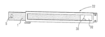
図3は、既存のトナーホッパ20およびシール片24が挿入され、取付けられた底部チャンバ22を示す。図示されたシール片24は、図3のシール片24に取付けられたハンドル26から分るように、元の製造者が販売するトナーホッパ20およびチャンバ22のためのものである。市販のカートリッジは、本発明に包含されないため図示されない、結合されたホッパ20および底部チャンバ22から容易に分離される第2の部分を有する。
【0017】
図4は、使用前に元のシール片24が填っていた溝部30に部分的に挿入された本発明によるシール片を示す(図4は、本発明を説明するためホッパ20から分離した底部22を示しているが、本発明の特徴によれば、ホッパ20とチャンバ22とを分離する必要はなく、実際上これらは超音波溶接で連結されていて、容易に分離することはできない。
【0018】
シール片1は、図3において、その発泡体7が上を向いていること表すため僅かに描かれている。)。底部チャンバ22は、下側開口32を有しており、この開口は矩形で、ホッパ20(図3)と連通し、周囲に原シール片24を保持していた溝部30を備える。本発明による取り替えシール片1は溝部30に部分的に挿入された状態で示されている。その巾は溝部30の巾よりやや小さく、高さは溝部30の高さより大きい(実際寸法は許容誤差によって異なる)。
【0019】
溝部30が片1の発泡ラミネート7を圧縮して完全密閉が達成される。Sール片1は、全体的に硬いため、溝部30の長さ方向への押圧力によって挿入することができる。シール片1の縮まった面取り端部は、溝部30の高さよりずっと小さくなっており、従って溝部30の奥までのシール片1の進入を許容するガイド端を構成する。
【0020】
シール片1の押圧は、片1の巾方向に対して横向きにピンチ・ローラを掛ける装置により自動化することができる。これらは発泡ラミネート7を強い力で変形させるので、前述したように接着剤の付着によって発泡体の弾性を失わないようにする必要がある。
【0021】
本発明による直接再挿入可能なシール片1は、コストのかかる挿入工具および作業を不要とするとともに、容易に分離できないように構成されたホッパ20とチャンバ22を分解する必要がないため、コスト効率が高い。柔軟層9の外側平滑面および支持層3の外側平滑面は挿入を促進し、柔軟層9の外側平滑面は、トナーホッパに向く粗面材又は多孔材を有するシール片とは対照的に、トナーをほとんど運び出すことはない。ホッパ20側に薄い柔軟層9を備える発泡体層7を用いれば、柔軟でない部材がホッパ20にある場合よりもトナー保持力が高くなる。溝部30にシール片1を完全に挿入することにより、搬送およびホッパ20内のトナーの取扱時に極めて効果的なシールが達成できる。
【0022】
上述の好適実施例は、市販の特定カートリッジの取り替え品として説明してきたが、ホッパの開口の周囲の内側溝部に開口する孔を有する他のトナーカートリッジにも使用可能である。
【0023】
【発明の効果】
本発明によるシール片は、長手方向の力で簡単に挿入できるので、ピンチ・ローラを用いた自動挿入が可能となり、コスト効率が高い。つまり、製造コストを低く押されることができる。
【0024】
また、このシールを用いれば、トナーホッパを隣接チャンバから分離して再び接着する必要がなくなり、詰め替えするカートリッジに工具を挿入する必要もなくなる。さらに、引き抜き時にトナーをくっつけて排出することもない。
【図面の簡単な説明】
【図1】図1は、シール片の斜視図である。
【図2】図2は、図1に示される2−2線に沿うシール片の断面図である。
【図3】図3は、本発明による挿入可能シール片が用いられる市販のシール片付きカートリッジの斜視図である。
【図4】図4は、ホッパを省略した、本発明によるシール片が一部挿入された底部チャンバの平面図である。
【符号の説明】
1 シール片
3 支持ラミネート層
4 面取り端部
5 穴部
7 発泡体ラミネート層
9 柔軟性ラミネート層
20 ホッパ
22 チャンバ
30 溝部
32 開口[0001]
[Industrial applications]
The present invention relates to refilling (sometimes referred to as regeneration) of an electrophotographic toner cartridge. Toner is typically removed from the cartridge and subjected to image development, thus emptying the cartridge toner. Certain cartridges are reusable by toner replacement (usually involving a reconditioning step), and it is this refilling of toner that is relevant to the present invention. To prevent toner leakage during transport of the cartridge to which the present invention pertains, the toner is contained in a removable sealable hopper chamber. In use, the seal is removed and the toner falls by gravity onto a portion of the cartridge that has a toner transport for image development. The present invention relates to a seal inserted prior to the above-mentioned filling to seal a toner in preparation for transportation of a hopper.
[0002]
[Prior art]
If the toner hopper is separated from the adjacent chamber of the toner cartridge, the seal can be easily applied by glue, heat fusing or other techniques not readily available with the two chambers attached. The present invention seeks to develop an insertable seal for a Canon SX toner cartridge. The current seal of this cartridge is a double-laminate of a thin polyethylene sheet material folded back in the longitudinal direction, with the laminate facing a toner hopper attached to the opening of the hopper. The seal extends from the cartridge and includes a plastic tab attached thereto to form a handle. In use, when the user pulls the handle, the mounting portion is broken by the pulling force, and the seal is removed. This seal is so thin that it cannot be reinserted into the cartridge.
[0003]
The toner hopper has an opening for pulling out a stopper and replacing the toner in the hopper. A seal is applied to the bottom opening of the toner hopper so that the refilled cartridge can be transported. A seal that can be easily and directly inserted into the groove of the hopper where the original seal was located eliminates the burden and cost of breaking the connection to the adjacent chamber of the toner hopper. It is also desirable to avoid the burden and cost of using a tool to enter the cartridge through the groove to transport the seal to a predetermined position or to apply adhesive or heat or the like.
[0004]
The present invention uses a piece comprising a support laminate and an elastic laminate. Such reinsertable seals are described in IBM Technical Bulletin, April 13, 1971, Vol. 13, No. 11, p. 3218, on a subject widely marketed since the early 1970's. Known from "Lid Assembly" co-authored by J. Rusher, J. P. Wang and F. W. Wills, and U.S. Pat. belongs to. In the present invention, the flexible outer layer is attached to the elastic laminate, which greatly facilitates insertion and can significantly reduce the amount of toner carried out when the seal strip is withdrawn.
[0005]
[Problems to be solved by the invention]
SUMMARY OF THE INVENTION It is an object of the present invention to provide a toner hopper seal piece that can be easily inserted by a longitudinal force, thereby automating the insertion operation, and further reducing the toner refilling cost of the hopper.
[0006]
Another object of the present invention is to provide a toner hopper seal piece that does not stick the toner and carry it out when pulled out.
[0007]
[Means for Solving the Problems]
The present invention provides a seal piece that can be inserted into an existing groove between a toner hopper and an adjacent chamber by a pressing force in a longitudinal direction. The seal has a smooth, heavy plastic base layer to provide support and hardness. A plastic foam having an inherent elasticity is arranged in the laminate part on the upper side of the base layer. A thin, smooth plastic layer is stuck on top of the foam. At the time of insertion, the foam side together with the thin plastic layer faces the toner hopper and coincides with the edge of the opening, thereby improving the sealing performance.
[0008]
The piece as a whole is sufficiently rigid to be pushed longitudinally into the groove of the cartridge, which is somewhat wider than the width of the seal. Since the height dimension of the groove is smaller than the thickness of the seal, the seal fills the vertical opening of the groove by some push of the foam. Smooth top and bottom plastic surfaces facilitate insertion and withdrawal by reducing friction, and the smooth plastic surface facing the toner can move farther without collecting toner. The strip has an extended handle for gripping during removal and a tapered end for guiding to the insertion site.
[0009]
【Example】
As shown in FIG. 1, a preferred sealing piece 1 according to the invention comprises a bottom support laminate layer 3 made of polyethylene terephthalate having a thickness of 0.35 mm (elongation 200%, tensile strength 17/18 KG / square mm). Set and the color is a natural color). It is made of a smooth, strong material and bends reasonably well by gravity, but is strong against longitudinal forces, ie hard. This piece is 310 mm long and 44.5 mm wide. This piece has, at one end in the longitudinal direction, a punched
[0010]
On top of the support 3 is provided a laminate layer 7 (FIG. 2) formed of a 1.25 mm thick polyethylene ether foam (this foam has a density of E-150, 1.5 lb /. Cubic feet, ie, 23-26.2 KG / mm, color is charcoal). This is an adhesive layer having elasticity that returns to its original shape after being crushed.
[0011]
On the upper side of the laminate layer 7, a laminate layer 9 made of polyethylene terephthalate having a thickness of 0.05 mm (elongation ratio is set to 150%, tensile strength is set to 21 / 25KG / square mm, and the color is neutral. Is provided). It is easily bent and consists of a smooth material.
[0012]
The foam laminate layer 7 is attached to the laminate layers 3 and 9 with an adhesive covering the side surfaces of the laminate layers 3 and 9 that are in contact with the laminate layer 7. In order to prevent the foam laminate layer 7 from losing elasticity, it is necessary to prevent the adhesive from entering the foam of the laminate layer 7. Adhesives that are liquid and viscous at the time of application are not suitable.
[0013]
The nature of a solid adhesive at the time of application is inherently suitable, and the property of penetrating into the foam can be easily identified and easily discriminated from the viewpoint of surface energy and the like. Heat activated adhesives based on polyethylene perform excellently in terms of foam elastic loss. Although the details of this adhesive are not known because it is not a seller, it is actually commercially available and information can be obtained if necessary.
[0014]
As shown in cross section in FIG. 2, the longitudinal end of the sealing piece 1 is linearly narrowed over a section of 1 mm from a
[0015]
The
[0016]
FIG. 3 shows the
[0017]
FIG. 4 shows the sealing piece according to the invention partially inserted into the
[0018]
The sealing piece 1 is slightly drawn in FIG. 3 to indicate that the foam 7 is facing up. ). The
[0019]
The
[0020]
The pressing of the sealing piece 1 can be automated by a device that applies a pinch roller transversely to the width direction of the piece 1. Since these deform the foam laminate 7 with a strong force, it is necessary not to lose the elasticity of the foam due to the adhesion of the adhesive as described above.
[0021]
The directly re-insertable sealing strip 1 according to the invention eliminates the need for costly insertion tools and operations and does not require disassembly of the
[0022]
Although the preferred embodiment described above has been described as a replacement for a particular commercially available cartridge, it can be used with other toner cartridges that have holes that open into an inner groove around the opening of the hopper.
[0023]
【The invention's effect】
Since the sealing piece according to the present invention can be easily inserted by a longitudinal force, it can be automatically inserted using a pinch roller, and is cost-effective. That is, the manufacturing cost can be kept low.
[0024]
Also, if this seal is used, there is no need to separate the toner hopper from the adjacent chamber and adhere again, and it is not necessary to insert a tool into the cartridge to be refilled. Further, the toner is not attached and discharged at the time of pulling out.
[Brief description of the drawings]
FIG. 1 is a perspective view of a seal piece.
FIG. 2 is a sectional view of the seal piece taken along line 2-2 shown in FIG. 1;
FIG. 3 is a perspective view of a commercially available cartridge with a seal piece in which the insertable seal piece according to the present invention is used.
FIG. 4 is a plan view of the bottom chamber in which a sealing piece according to the present invention is partially inserted, in which a hopper is omitted.
[Explanation of symbols]
REFERENCE SIGNS LIST 1 seal piece 3
Claims (10)
前記シール片の外側を構成する側が滑らかな支持ラミネート層と、
前記支持ラミネート層に取着された弾性発泡体ラミネート層と、
前記支持ラミネート層と反対側の前記弾性ラミネート層に取着され、前記弾性ラミネート層から遠い側が滑らかな柔軟性ラミネート層と、
から成り、長手方向の押圧力に対して堅固であり、かつ、前記カートリッジを結像に使用するための準備の際に前記カートリッジから前記シールを引き抜くためのハンドル部を一端に有することを特徴とするトナーホッパ用シール片。A toner hopper seal piece having a groove around an opening of the toner cartridge,
A support laminate layer having a smooth outer side of the seal piece,
An elastic foam laminate layer attached to the support laminate layer,
A flexible laminate layer attached to the elastic laminate layer on the opposite side of the support laminate layer, and having a smooth side far from the elastic laminate layer;
Characterized in that it has a handle portion at one end, which is rigid against a longitudinal pressing force, and which pulls out the seal from the cartridge when preparing to use the cartridge for imaging. Toner hopper seal strip.
使用時に結像用のトナーを受取るための連結チャンバと、
前記チャンバと連通する前記ホッパの開口と、
前記開口の周囲の溝部と、
前記溝部に位置するシール片と、を備えたトナーカートリッジであって、
前記シール片は、前記チャンバと対面する支持ラミネート層と、前記ホッパと対面する側において前記支持ラミネート層に取着された弾性発泡体ラミネート層と、前記弾性発泡体ラミネート層に取着され、前記ホッパと対面する側が滑らかな柔軟性ラミネート層とを有し、
前記シール片は、前記溝部が、トナーを前記ホッパに保持するよう前記弾性発泡体ラミネート層を前記シール片の厚さ方向に押圧するような厚さを有していることを特徴とするトナーカートリッジ。And the door Nahoppa,
A coupling chamber for receiving imaging toner during use;
An opening of the hopper communicating with the chamber;
A groove around the opening,
A seal piece located in the groove ,
The seal piece is attached to the support laminate layer facing the chamber, the elastic foam laminate layer attached to the support laminate layer on the side facing the hopper, and the elastic foam laminate layer, The side facing the hopper has a smooth flexible laminate layer,
The toner cartridge, wherein the seal piece has a thickness such that the groove presses the elastic foam laminate layer in a thickness direction of the seal piece so as to hold toner in the hopper. .
Applications Claiming Priority (2)
| Application Number | Priority Date | Filing Date | Title |
|---|---|---|---|
| US08/054,178 US5335831A (en) | 1993-04-30 | 1993-04-30 | Insertable toner hopper sealing strip |
| US08/054,178 | 1993-04-30 |
Publications (2)
| Publication Number | Publication Date |
|---|---|
| JPH07325537A JPH07325537A (en) | 1995-12-12 |
| JP3554792B2 true JP3554792B2 (en) | 2004-08-18 |
Family
ID=21989266
Family Applications (1)
| Application Number | Title | Priority Date | Filing Date |
|---|---|---|---|
| JP01598694A Expired - Fee Related JP3554792B2 (en) | 1993-04-30 | 1994-01-14 | Seal piece for toner hopper |
Country Status (5)
| Country | Link |
|---|---|
| US (1) | US5335831A (en) |
| EP (1) | EP0622705B1 (en) |
| JP (1) | JP3554792B2 (en) |
| AU (1) | AU663456B2 (en) |
| DE (1) | DE69310715T2 (en) |
Families Citing this family (17)
| Publication number | Priority date | Publication date | Assignee | Title |
|---|---|---|---|---|
| US5876541A (en) * | 1990-12-07 | 1999-03-02 | Chitouras; Costa G. | Method for resealing a toner cartridge |
| JP2678999B2 (en) * | 1990-12-07 | 1997-11-19 | チタラス,コスタ・ジー | Toner cartridge resealing method |
| US5392963A (en) * | 1993-06-01 | 1995-02-28 | Hewlett-Packard Company | Refurbished toner cartridge |
| DE69332403T2 (en) * | 1993-06-01 | 2003-07-03 | Hewlett-Packard Co. (N.D.Ges.D.Staates Delaware), Palo Alto | Toner seal on a toner cartridge |
| JP3210175B2 (en) * | 1993-06-10 | 2001-09-17 | キヤノン株式会社 | Developer supply container and method of assembling the container |
| DE69434930T2 (en) * | 1993-07-14 | 2007-06-28 | Canon K.K. | Seal, process unit recycling process and image forming apparatus |
| JP3308671B2 (en) * | 1993-08-10 | 2002-07-29 | キヤノン株式会社 | Seal member, developer container, and process cartridge |
| US5404212A (en) * | 1993-09-24 | 1995-04-04 | Laser Ink Ltd. | Toner cartridge seal |
| US5512987A (en) * | 1994-05-25 | 1996-04-30 | Xerox Corporation | Sealing strip adhering method |
| US5872680A (en) * | 1995-09-14 | 1999-02-16 | Iomega Corporation | Disk drive seal attached to a motor ring flange |
| US5555080A (en) * | 1995-12-08 | 1996-09-10 | Eastman Kodak Company | Slide cover for marking particle cartridge |
| US5729795A (en) * | 1996-09-19 | 1998-03-17 | Genicom Corporation | Reconditioning of electrostatographic cartridges |
| US6044238A (en) * | 1997-10-17 | 2000-03-28 | Nu-Kote International, Inc. | Replacement seal assembly for a toner cartridge |
| US6596110B1 (en) | 1999-08-10 | 2003-07-22 | Costa G. Chitouras | Apparatus and method for modifying toner cartridges for sealing |
| EP1799434A2 (en) * | 2004-09-23 | 2007-06-27 | CHITOURAS, Costa G. | Method of sealing remanufactured split toner cartridges |
| TWI339780B (en) | 2005-07-28 | 2011-04-01 | Rohm & Haas Elect Mat | Stripper |
| USD722641S1 (en) * | 2013-11-14 | 2015-02-17 | Flo-Tech, Llc | Toner cartridge seal |
Family Cites Families (5)
| Publication number | Priority date | Publication date | Assignee | Title |
|---|---|---|---|---|
| US4862210A (en) * | 1988-02-25 | 1989-08-29 | Access Computer Products, Inc. | Replaceable seal assembly for toner cartidges and method of use |
| US4930684A (en) * | 1988-08-02 | 1990-06-05 | Data Products Corporation | Closure strip and method for remanufacturing a toner cartridge and toner cartridge |
| US5080745A (en) * | 1990-05-29 | 1992-01-14 | Leslie Paull | Toner bin seal and sealing method |
| US5184182A (en) * | 1992-03-04 | 1993-02-02 | Michlin Steven B | Copier and printer toner hopper sealing device |
| US5258814A (en) * | 1992-06-10 | 1993-11-02 | Davies Wilkins L | Toner cartridge seal |
-
1993
- 1993-04-30 US US08/054,178 patent/US5335831A/en not_active Expired - Lifetime
- 1993-12-20 DE DE69310715T patent/DE69310715T2/en not_active Expired - Fee Related
- 1993-12-20 EP EP93310270A patent/EP0622705B1/en not_active Expired - Lifetime
-
1994
- 1994-01-14 JP JP01598694A patent/JP3554792B2/en not_active Expired - Fee Related
- 1994-02-28 AU AU56471/94A patent/AU663456B2/en not_active Ceased
Also Published As
| Publication number | Publication date |
|---|---|
| AU663456B2 (en) | 1995-10-05 |
| AU5647194A (en) | 1994-11-03 |
| DE69310715T2 (en) | 1997-12-18 |
| US5335831A (en) | 1994-08-09 |
| DE69310715D1 (en) | 1997-06-19 |
| JPH07325537A (en) | 1995-12-12 |
| EP0622705A1 (en) | 1994-11-02 |
| EP0622705B1 (en) | 1997-05-14 |
Similar Documents
| Publication | Publication Date | Title |
|---|---|---|
| JP3554792B2 (en) | Seal piece for toner hopper | |
| US4930684A (en) | Closure strip and method for remanufacturing a toner cartridge and toner cartridge | |
| US5258814A (en) | Toner cartridge seal | |
| JP3727655B2 (en) | High burst strength adhesive closure for flexible bags | |
| CN103649846B (en) | Developer-containing unit, handle box and electrophotographic imaging forming apparatus | |
| US5282003A (en) | Copier and printer toner hopper sealing device | |
| US6609789B1 (en) | Ink cartridge | |
| CN103649847A (en) | Developer storage container, developer storage unit, process cartridge, and electrophotographic image formation device | |
| CN103649845A (en) | Developer accommodating container, developer accommodating unit, process cartridge, electrophotographic image forming apparatus | |
| JP2014056025A (en) | Developer storage container, process cartridge, and image forming apparatus | |
| US5930559A (en) | Means for the sealing of a toner cartridge | |
| EP0131697A2 (en) | Toner cartridge | |
| US7333747B2 (en) | Toner cartridge seal assembly | |
| US5409143A (en) | Flexible tube for the packaging of pasty products | |
| US5907747A (en) | Prefilled, presealed toner cartridge insert | |
| JP3963894B2 (en) | Carton for powder | |
| JP2742653B2 (en) | Compressed futon storage bag | |
| GB2289238A (en) | Seal for a toner cartridge assembly | |
| US20050152623A1 (en) | Sealable bag | |
| JPH0160142B2 (en) | ||
| EP1163990A3 (en) | Method for enclosing a foamable composition in a flexible bag | |
| JPH04293066A (en) | developing device | |
| GB2321219A (en) | Seal for a toner cartridge assembly and a process of re-charging a toner cartridge using such a seal | |
| JP2006111275A (en) | Spout pack made of synthetic resin | |
| US20060198656A1 (en) | Toner cartridge seal assembly |
Legal Events
| Date | Code | Title | Description |
|---|---|---|---|
| A01 | Written decision to grant a patent or to grant a registration (utility model) |
Free format text: JAPANESE INTERMEDIATE CODE: A01 Effective date: 20040210 |
|
| A61 | First payment of annual fees (during grant procedure) |
Free format text: JAPANESE INTERMEDIATE CODE: A61 Effective date: 20040223 |
|
| A61 | First payment of annual fees (during grant procedure) |
Free format text: JAPANESE INTERMEDIATE CODE: A61 Effective date: 20040413 |
|
| R150 | Certificate of patent or registration of utility model |
Free format text: JAPANESE INTERMEDIATE CODE: R150 |
|
| R250 | Receipt of annual fees |
Free format text: JAPANESE INTERMEDIATE CODE: R250 |
|
| FPAY | Renewal fee payment (event date is renewal date of database) |
Free format text: PAYMENT UNTIL: 20090521 Year of fee payment: 5 |
|
| LAPS | Cancellation because of no payment of annual fees |