JP3554504B2 - Reciprocating pump - Google Patents
Reciprocating pump Download PDFInfo
- Publication number
- JP3554504B2 JP3554504B2 JP13116099A JP13116099A JP3554504B2 JP 3554504 B2 JP3554504 B2 JP 3554504B2 JP 13116099 A JP13116099 A JP 13116099A JP 13116099 A JP13116099 A JP 13116099A JP 3554504 B2 JP3554504 B2 JP 3554504B2
- Authority
- JP
- Japan
- Prior art keywords
- communication pipe
- guide pin
- discharge
- valve
- water
- Prior art date
- Legal status (The legal status is an assumption and is not a legal conclusion. Google has not performed a legal analysis and makes no representation as to the accuracy of the status listed.)
- Expired - Fee Related
Links
Images


Landscapes
- Reciprocating Pumps (AREA)
- Details Of Reciprocating Pumps (AREA)
Description
【0001】
【発明の属する技術分野】
本発明は往復ポンプに係わり、特に連通管をマニフォールドの外部より容易に位置合わせ可能で、吸排水効率が高く、かつ簡単な構造で空気抜きが行える往復ポンプに関する。
【0002】
【従来の技術】
図5に三連式プランジャポンプ10の垂直縦断面図、図6にこの三連式プランジャポンプ10の流体部の部分拡大図を示す。プランジャ1は、コンロッド3を介してクランク軸5に連結し、クランク軸5の回転に伴って往復動する。
【0003】
プランジャ1は、スタッフィングボックス7内部をシール9に沿って摺動自在である。図中、プランジャ1等は、上死点位置にあるときと下死点位置にあるときとを併記して記載している。
【0004】
スタッフィングボックス7の端部には、マニフォールド11が固着されている。マニフォールド11の下部には、吸水口13が設けられている。プランジャ1の往復動により吸水口13から吸水された流体は、吸水弁15を通ってポンプ室17内に導かれる。
【0005】
吸水弁15は、吸水弁バネ19により付勢されて吸水弁座21に着座するようになっている。吸水弁座21の上部には、中空の連通管23が配設されている。この中空の連通管23の内側には、ポンプ室17が形成され、連通管23の側部には、4個の穴が四方に開けられている。そして、プランジャ1の往復動に伴い、流体がこの穴を通じてスタッフィングボックス7側に吸排される。
【0006】
連通管23の上部には、吐出弁座25が配設されている。吐出弁29は、吐出弁バネ27により付勢されて吐出弁座25に着座するようになっている。吐出弁座25の上部には、中空の連通管31が配設されている。
【0007】
この中空の連通管31の側部には、4個の穴が四方に開けられている。そして、プランジャ1の往復動に伴い、流体がこの穴を通じて吐出口33側に吐出される。吐出口33は、吸水口13と同方向に図6中に点線で示すように手前側に開口されている。
【0008】
連通管31は、プラグ35を挟み上方よりプラグ37によりネジ付け固定されている。このように、プランジャ1の往復動により、ポンプ室17とプランジャ1の端部で形成される容積が増減される。そして、吸水弁15及び吐出弁29の作用により、吸水口13からポンプ室17を経て吐出口33への一方向の液体の流れを許容する。
【0009】
【発明が解決しようとする課題】
ところで、従来の連通管23及び連通管31は、組み付け時に周方向に回動し易い。このため、側部に設けられる穴は、連通管23の場合にはプランジャ1の往復運動方向に一致するとは限らず、吸排水効率が低くなるおそれがあった。
【0010】
従って、穴が周方向のどの位置になっても吸排水の影響を受け難くするため、四方に4個穴を設けたり、特に吸水側は流れの抵抗をできるだけなくすために、充分な穴の大きさを確保する等の方策が採られてきている。
【0011】
しかしながら、複数個の穴を設けたり、その穴径を大きくすることは、連通管23の上下方向の圧縮強度が弱くなる。また、穴の位置が、プランジャ1の往復運動方向にどの程度一致しているかによって吸水性能が異なってしまう。
【0012】
この点は、連通管31でも同様であり、排水効率を上げるため、複数個の穴を設けたり、その穴径を大きくすることは、連通管31の上下方向の圧縮強度が弱くなる等の欠点を生ずる。
【0013】
また、かかる往復動ポンプにおいて、ポンプが高速高圧タイプになると、吸水がし難くなる場合を生ずる。これは、高速においては、急激なプランジャ1の運動により、圧縮された空気がポンプ室17内にとどまり、吸水行程に入ったときに吸い込みの能力が低くなってしまうためである。
【0014】
このため、小型高速ポンプなどにおいては、吐出口33とは別に、ポンプ室17の流体の外部への開放を行う図示しない空気抜き用ヴァルブを設けて、ポンプ運転の初期段階や、一旦ポンプを停止した際などに、手動でこの空気抜き用ヴァルブを開いてポンプ作用がスムーズに行えるようにしている。そして、その後空気抜き用ヴァルブを閉じて通常の運転を開始している。
【0015】
本発明はこのような従来の課題に鑑みてなされたもので、連通管をマニフォールドの外部より容易に位置合わせ可能で、吸排水効率が高く、かつ簡単な構造で空気抜きが行える往復ポンプを提供することを目的とする。
【0016】
【課題を解決するための手段】
このため本発明(請求項1)は、プランジャ(1)を往復運動させる駆動手段(3、5)と、前記プランジャ(1)の往復運動により吸水のとき開かれ、吸水口(13)より流体を導入する吸水弁(15)と、該吸水弁(15)が着座する吸水弁座(21)と、前記プランジャ(1)の往復運動により排水のとき開かれ、吐出口(33)より流体を吐出する吐出弁(29)と、該吐出弁(29)が着座する吐出弁座(25)と、該吐出弁座(25)と前記吸水弁座(21)の間に環装され、前記プランジャ(1)の往復運動により流体が吸排される吸排口(51)が設けられた吸水側連通管(23)と、前記吐出弁座(25)を挟み前記吸水側連通管(23)の反対側に環装され、前記プランジャ(1)の往復運動により流体が排出される排出口が設けられた吐出側連通管(31)と、前記吸水弁(15)、前記吸水弁座(21)、前記吐出弁(29)、前記吐出弁座(25)、前記吸水側連通管(23)及び前記吐出側連通管(31)が収納されたマニフォールド(11)と、前記吸水側連通管(23)及び/又は前記吐出側連通管(31)を前記マニフォールド(11)の外部より貫通されたガイドピン(61)により位置合わせ固定する固定手段(53、60、65、73、55、75)とを備えて構成した。
【0017】
吸水側連通管(23)は、吐出弁座(25)と吸水弁座(21)の間に環装する。そして、この吸水側連通管(23)には、プランジャ(1)の往復運動により流体が吸排される吸排口(51)を設ける。また、吐出側連通管(31)は、吐出弁座(25)を挟み吸水側連通管(23)の反対側に環装する。そして、この吐出側連通管(31)には、プランジャ(1)の往復運動により流体が排出される排出口を設ける。
【0018】
固定手段(53、60、65、73、55、75)は、吸水側連通管(23)及び/又は吐出側連通管(31)を、マニフォールド(11)の外部より貫通されたガイドピン(61)により位置合わせ固定する。ガイドピン(61)による位置合わは、吸水側連通管(23)及び/又は吐出側連通管(31)側に、凹部を設けたり、貫通穴(55、75)を設けることで可能である。
【0019】
この固定により吸水側連通管(23)及び/又は吐出側連通管(31)を所望とする位置に位置合わせして止めることが出来る。吸水側連通管(23)及び/又は吐出側連通管(31)としたのは、固定手段(53、60、65、73、55、75)を吸水側連通管(23)と吐出側連通管(31)の双方に配設してもよいし、いずれか一方のみに配設してもよいためである。
【0020】
以上により、吸水側連通管(23)及び/又は吐出側連通管(31)を所望とする位置に位置合わせ出来るため、給排水効率が一定する。また、その位置合わせ作業も、マニフォールド(11)の外部から出来るため簡単である。
【0021】
かかる位置合わせを可能としたため、吸水側連通管(23)及び/又は吐出側連通管(31)に対し、不必要に穴の個数を増やしたり、穴径を大きくする等の必要は無くなる。このため、吸水側連通管(23)及び/又は吐出側連通管(31)の強度を保つことが出来る。
【0022】
また、本発明(請求項2)は、前記固定手段(53、60、65、73、55、75)は、前記吸水側連通管(23)及び/又は前記吐出側連通管(31)の所定位置に設けられたガイドピン穴(53、73)と、該ガイドピン穴(53、73)と位置が揃うように、前記マニフォールド(11)に設けられた貫通穴(55、75)と、該ガイドピン穴(53、73)及び前記貫通穴(55、75)を貫通するガイドピン(61)と、該ガイドピン(61)に一体に形成され、前記貫通穴(55、75)を前記マニフォールド(11)外部より覆い就座するバルブ(63)と、前記ガイドピン(61)に貫通され、前記バルブ(63)を前記貫通穴(55、75)に対し密着させるプラグ(65)とを備えて構成した。 ガイドピン(61)を、吸水側連通管(23)及び/又は吐出側連通管(31)に設けたガイドピン穴(53、73)とマニフォールド(11)に設けた貫通穴(55、75)とに貫通させる。ガイドピン穴(53、73)と貫通穴(55、75)とを貫通させればよいので、位置合わせ作業は楽に行える。
【0023】
ガイドピン(61)の周囲には、バルブ(63)が一体に形成されている。バルブ(63)は、貫通穴(55、75)をマニフォールド(11)外部より覆い就座する。そして、このバルブ(63)をプラグ(65)により貫通穴(55、75)に対し密着させる。
【0024】
更に、本発明(請求項3)は、前記固定手段(53、60、65、73、55、75)は、前記ガイドピン(61)の貫通により、前記吸排口(51)が前記プランジャ(1)の往復運動方向に一致及び/又は前記排出口が前記吐出口(33)に方向一致されることを特徴とする。
【0025】
吸排口(51)をプランジャ(1)の往復運動方向に一致させたり、排出口を吐出口(33)に方向一致させれば、流体の流れはスムーズになり、給排水効率を向上させることが出来る。
【0026】
更に、本発明(請求項4)は、前記固定手段(53、60、65、73、55、75)は、前記プラグ(65)が螺進退操作可能であり、該プラグ(65)を後退させたとき、前記ガイドピン(61)と前記貫通穴(55、75)間、前記バルブ(63)と前記貫通穴(55、75)間、前記バルブ(63)と前記プラグ(65)間、前記プラグ(65)と前記ガイドピン(61)間を連絡する空気抜き通路が形成されることを特徴とする。
【0027】
プラグ(65)は進出させれば、バルブ(63)を貫通穴(55、75)に対し密着させることが出来る。一方、後退させれば空気抜き通路が形成され、この通路から往復ポンプの初期運転時に空気抜きを行うことが出来る。
【0028】
このように、固定手段(53、60、65、73、55、75)は、吸水側連通管(23)及び/又は吐出側連通管(31)の組立時の位置合わせ機能と、初期運転時の空気抜き機能とを併せ持たせることが出来、構成が簡単で安価である。
【0029】
【発明の実施の形態】
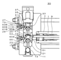
以下、本発明の実施形態を図面に基づいて説明する。図1に本発明の第1実施形態である三連式プランジャポンプ20の部分拡大図を示す。図1において、連通管23の側部には、プランジャ1の往復運動方向に一致する位置に吸排口51が一つ設けられている。そして、同じ連通管23の側部で吸排口51と対峙する位置には、ガイドピン穴53が設けられている。
【0030】
また、マニフォールド11の側部で、かつガイドピン穴53と一致する位置には、貫通穴55が設けられている。貫通穴55は、外側に開口径が大きく拡張され、その拡張された内周には、雌ネジが螺刻されている。
【0031】
このガイドピン穴53と貫通穴55を、ガイドピン付バルブ60Aが貫通している。ガイドピン付バルブ60Aの詳細図を図2に示す。ガイドピン61Aの周囲には、右端をテーパ加工され、左端が平面であるこま形のバルブ63Aが一体に形成されている。
【0032】
プラグ65Aは、このガイドピン61Aに貫通され、右端部外周には、雄ネジ67Aが螺刻され、貫通穴55の雌ネジと螺合するようになっている。ガイドピン61Aの直径φAは、プラグ65Aの内径φBより多少小さく加工されており、また、貫通穴55の開口径よりも同様に小さく加工されている。
【0033】
次に、本発明の第1の実施形態の作用を説明する。
連通管23をマニフォールド11に組み込む際に、ガイドピン付バルブ60Aをガイドピン穴53と貫通穴55に貫通させる。貫通されたときには、吸排口51がプランジャ1の往復運動方向に一致する。このため、簡単に位置合わせ作業を行える。
【0034】
また、従来の三連式プランジャポンプ10のように、すべて組込まれた後に、プラグ37をマニフォールド11にネジ込むタイプにおいては、ネジ込み時に各部品がマニフォールド11内で回転してしまったが、ガイドピン61Aが挿入されているので回転せずに、吸排口51の位置方向が保たれ、流体の流れはスムーズに一定となる。
【0035】
このため、吸排水効率は高くすることが出来る。更に、必要最小限の開口面積を確保すればよいので、強度も保持出来る。
ガイドピン付バルブ60Aは、プラグ65Aを貫通穴55に螺入させることで、バルブ63Aを貫通穴55に対し密着させる。
【0036】
一方、ポンプ運転の初期段階等には、プラグ65Aを緩める。このプラグ65Aを緩めたときの様子を図3に示す。このとき、ガイドピン61Aと貫通穴55間、バルブ63Aと貫通穴55間、バルブ63Aとプラグ65A間、プラグ65Aとガイドピン61A間を連絡する空気抜き通路が形成される。
このため、別途空気抜き用ヴァルブを設ける必要はなく、構成も簡単で安価である。
【0037】
次に、本発明の第2の実施形態について説明する。
本発明の第2の実施形態は、連通管31側にも連通管23側と同様にガイドピン付バルブ60Bを配設する点にある。図4に本発明の第2実施形態である三連式プランジャポンプ30の部分拡大図を示す。
【0038】
図4において、連通管31の側部には、図示しない排出口が吐出口33に方向一致するように一つ設けられている。そして、同じ連通管31の側部には、連通管23のガイドピン穴53と同じ向きにガイドピン穴73が設けられている。
【0039】
更に、マニフォールド11の側部で、かつガイドピン穴73と一致する位置には、貫通穴75が設けられている。貫通穴75は、外側に開口径が大きく拡張され、その拡張された内周には、雌ネジが螺刻されている。
【0040】
このガイドピン穴73と貫通穴75を、ガイドピン付バルブ60Bが貫通している。ガイドピン61Bの周囲には、右端をテーパ加工され、左端が平面であるこま形のバルブ63Bが一体に形成されている。
プラグ65Bは、このガイドピン61Bに貫通され、右端部外周には、雄ネジ67Bが螺刻され、貫通穴75の雌ネジと螺合するようになっている。
【0041】
次に、本発明の第2の実施形態の作用を説明する。
連通管31をマニフォールド11に組み込む際に、ガイドピン付バルブ60Bをガイドピン穴73と貫通穴75に貫通させる。貫通されたときには、排出口が吐出口33に方向一致する。このため、簡単に位置合わせ作業を行える。また、この際の排水効率は、流体の流れがスムーズな分高くすることが出来る。更に、必要最小限の開口面積を確保すればよいので、強度も保持出来る。
【0042】
三連式プランジャポンプ10では、一つの吐出口33に対し、3つの連通管31が並列に存在しているが、それぞれの連通管31に開けられた排出口は、すべて吐出口33に方向一致させることが出来る。
ガイドピン付バルブ60Bは、プラグ65Bを貫通穴75に螺入させることで、バルブ63Bを貫通穴75に対し密着させる。
【0043】
一方、ポンプ運転の初期段階等には、プラグ65Bを緩めることで空気抜きを行える。本発明の第2の実施形態では、ガイドピン付バルブ60Aとガイドピン付バルブ60Bの両方を備える場合について説明したが、ガイドピン付バルブ60Bのみを配設することも可能である。
【0044】
プラグ65Bを緩め、空気抜きを行う場合には、プラグ65Aを緩め、空気抜きを行う場合よりも空気抜きの効果は大きいと考えられる。これは、プラグ65Bにより空気抜きを行う方が、プランジャ1の往復運動による真空発生時に、逆に外部から空気を吸う恐れが少ないからである。
【0045】
以上により、連通管31に対しても、不必要に穴の個数を増やしたり、穴径を大きくする等の必要は無くなる。このため、連通管31の強度を保つことが出来る。また、流体の流れもスムーズである。
【0046】
【発明の効果】
以上説明したように本発明によれば、吸水側連通管(23)及び/又は吐出側連通管(31)をマニフォールド(11)の外部より貫通されたガイドピン(61)により位置合わせ固定可能としたため、位置合わせ作業が簡単である。
【0047】
従って、不必要に穴の個数を増やしたり、穴径を大きくする等の必要は無くなる。このため、吸水側連通管(23)及び/又は吐出側連通管(31)の強度を保つことが出来る。
【0048】
また、プラグ(65)を螺進退操作可能とし、プラグ(65)を後退させたとき、空気抜き通路を形成することとしたので、吸水側連通管(23)及び/又は吐出側連通管(31)の組立時の位置合わせ機能と、初期運転時の空気抜き機能とを併せ持たせることが出来、構成が簡単で安価である。
【図面の簡単な説明】
【図1】本発明の第1実施形態である三連式プランジャポンプの部分拡大図
【図2】ガイドピン付バルブの詳細図
【図3】プラグを緩めたときの様子
【図4】本発明の第2実施形態である三連式プランジャポンプの部分拡大図
【図5】従来の三連式プランジャポンプの垂直縦断面図
【図6】従来の三連式プランジャポンプの流体部の部分拡大図
【符号の説明】
1 プランジャ
10、20、30 三連式プランジャポンプ
11 マニフォールド
13 吸水口
15 吸水弁
17 ポンプ室
21 吸水弁座
23、31 連通管
25 吐出弁座
29 吐出弁
33 吐出口
51 吸排口
53、73 ガイドピン穴
55、75 貫通穴
60A、60B ガイドピン付バルブ
61A、61B ガイドピン
63A、63B バルブ
65A、65B プラグ[0001]
TECHNICAL FIELD OF THE INVENTION
The present invention relates to a reciprocating pump, and more particularly to a reciprocating pump capable of easily aligning a communication pipe from the outside of a manifold, having high suction / drainage efficiency, and capable of removing air with a simple structure.
[0002]
[Prior art]
FIG. 5 is a vertical longitudinal sectional view of the
[0003]
The
[0004]
A
[0005]
The
[0006]
A
[0007]
Four holes are formed in four sides on the side of the
[0008]
The
[0009]
[Problems to be solved by the invention]
By the way, the
[0010]
Therefore, in order to make the hole hardly affected by water absorption and drainage at any position in the circumferential direction, four holes are provided on all sides, and especially the water absorption side has a sufficient hole size to minimize the flow resistance. Measures have been taken, such as ensuring the quality.
[0011]
However, providing a plurality of holes or increasing the diameter of the holes reduces the compressive strength of the
[0012]
The same is true for the
[0013]
Further, in such a reciprocating pump, if the pump is of a high-speed and high-pressure type, water absorption may be difficult. This is because at a high speed, the sudden movement of the
[0014]
For this reason, in a small high-speed pump or the like, a vent valve (not shown) for opening the fluid in the
[0015]
The present invention has been made in view of such a conventional problem, and provides a reciprocating pump capable of easily positioning a communication pipe from the outside of a manifold, having a high suction / drainage efficiency, and capable of removing air with a simple structure. The purpose is to:
[0016]
[Means for Solving the Problems]
Therefore, the present invention (Claim 1) provides a driving means (3, 5) for reciprocating the plunger (1), and opens when water is absorbed by the reciprocating movement of the plunger (1). , A water absorption valve seat (21) on which the water absorption valve (15) is seated, and a reciprocating motion of the plunger (1), which is opened at the time of drainage to discharge fluid from the discharge port (33). A discharge valve (29) for discharging, a discharge valve seat (25) on which the discharge valve (29) is seated, and a ring mounted between the discharge valve seat (25) and the water absorption valve seat (21); (1) a suction-side communication pipe (23) provided with a suction / discharge port (51) through which fluid is sucked and discharged by reciprocation; and an opposite side of the suction-side communication pipe (23) across the discharge valve seat (25). And a drain from which the fluid is discharged by the reciprocating motion of the plunger (1). A discharge side communication pipe (31) provided with a port, the water suction valve (15), the water suction valve seat (21), the discharge valve (29), the discharge valve seat (25), and the water suction side communication pipe (31); 23) and the manifold (11) in which the discharge-side communication pipe (31) is housed, and the water-absorption-side communication pipe (23) and / or the discharge-side communication pipe (31) penetrating from outside the manifold (11). And fixing means (53, 60, 65, 73, 55, 75) for positioning and fixing with the provided guide pin (61).
[0017]
The water-absorbing communication pipe (23) is installed between the discharge valve seat (25) and the water-absorbing valve seat (21). The suction-side communication pipe (23) is provided with a suction / discharge port (51) through which fluid is sucked / discharged by reciprocating motion of the plunger (1). The discharge-side communication pipe (31) is installed around the discharge valve seat (25) on the side opposite to the water-absorption-side communication pipe (23). The discharge side communication pipe (31) is provided with a discharge port through which the fluid is discharged by the reciprocating motion of the plunger (1).
[0018]
The fixing means (53, 60, 65, 73, 55, 75) is provided with a guide pin (61) which penetrates the water suction side communication pipe (23) and / or the discharge side communication pipe (31) from outside the manifold (11). ) To fix the position. Positioning by the guide pin (61) can be performed by providing a concave portion or providing a through hole (55, 75) on the water-absorbing communication pipe (23) and / or the discharge communication pipe (31).
[0019]
By this fixing, the water-absorbing-side communication pipe (23) and / or the discharge-side communication pipe (31) can be positioned and stopped at a desired position. The water-absorbing-side communication pipe (23) and / or the discharge-side communication pipe (31) are used as fixing means (53, 60, 65, 73, 55, 75). This is because they may be provided on both sides of (31) or may be provided on only one of them.
[0020]
As described above, since the water suction side communication pipe (23) and / or the discharge side communication pipe (31) can be positioned at a desired position, the water supply / drainage efficiency is constant. Further, the positioning operation can be performed easily from the outside of the manifold (11).
[0021]
Since such alignment is enabled, it is not necessary to unnecessarily increase the number of holes or increase the hole diameter with respect to the suction side communication pipe (23) and / or the discharge side communication pipe (31). For this reason, the strength of the suction-side communication pipe (23) and / or the discharge-side communication pipe (31) can be maintained.
[0022]
Further, according to the present invention (claim 2), the fixing means (53, 60, 65, 73, 55, 75) may be configured such that the water-absorbing-side communication pipe (23) and / or the discharge-side communication pipe (31) are fixed. A guide pin hole (53, 73) provided at a position; a through-hole (55, 75) provided at the manifold (11) such that the position is aligned with the guide pin hole (53, 73); A guide pin (61) penetrating through the guide pin holes (53, 73) and the through holes (55, 75), and is formed integrally with the guide pin (61), and the through holes (55, 75) are connected to the manifold. (11) A valve (63) covered and seated from the outside, and a plug (65) penetrated by the guide pin (61) and bringing the valve (63) into close contact with the through holes (55, 75). Was configured. The guide pin (61) is provided with a guide pin hole (53, 73) provided in the water suction side communication pipe (23) and / or the discharge side communication pipe (31) and a through hole (55, 75) provided in the manifold (11). And let through. Since the guide pin holes (53, 73) and the through holes (55, 75) may be penetrated, the positioning operation can be performed easily.
[0023]
A valve (63) is integrally formed around the guide pin (61). The valve (63) covers the through holes (55, 75) from the outside of the manifold (11) and sits down. Then, the valve (63) is brought into close contact with the through holes (55, 75) by the plug (65).
[0024]
Further, according to the present invention (claim 3), the fixing means (53, 60, 65, 73, 55, 75) can be configured such that the guide pin (61) penetrates the suction / discharge port (51) to allow the plunger (1) to move. ) And / or the discharge port is aligned with the discharge port (33).
[0025]
If the suction port (51) is aligned with the reciprocating motion direction of the plunger (1) or the discharge port is aligned with the discharge port (33), the flow of the fluid becomes smooth and the efficiency of water supply and drainage can be improved. .
[0026]
Further, according to the present invention (claim 4), in the fixing means (53, 60, 65, 73, 55, 75), the plug (65) can be operated to advance and retreat, and the plug (65) is retracted. At the time, between the guide pin (61) and the through hole (55, 75), between the valve (63) and the through hole (55, 75), between the valve (63) and the plug (65), An air vent passage communicating between the plug (65) and the guide pin (61) is formed.
[0027]
When the plug (65) is advanced, the valve (63) can be brought into close contact with the through holes (55, 75). On the other hand, if it is retracted, an air vent passage is formed, from which air can be vented during the initial operation of the reciprocating pump.
[0028]
As described above, the fixing means (53, 60, 65, 73, 55, 75) is provided with a positioning function at the time of assembling the suction side communication pipe (23) and / or the discharge side communication pipe (31), and at the time of initial operation. The air vent function can be provided together, and the configuration is simple and inexpensive.
[0029]
BEST MODE FOR CARRYING OUT THE INVENTION
Hereinafter, embodiments of the present invention will be described with reference to the drawings. FIG. 1 shows a partially enlarged view of a
[0030]
Further, a through
[0031]
The
[0032]
The
[0033]
Next, the operation of the first embodiment of the present invention will be described.
When assembling the
[0034]
Further, in a type in which the
[0035]
For this reason, the suction and drainage efficiency can be increased. Further, since a minimum necessary opening area may be ensured, the strength can be maintained.
The valve with
[0036]
On the other hand, at an initial stage of the pump operation, the
Therefore, there is no need to provide a separate air vent valve, and the configuration is simple and inexpensive.
[0037]
Next, a second embodiment of the present invention will be described.
The second embodiment of the present invention resides in that a
[0038]
In FIG. 4, one discharge port (not shown) is provided on the side of the
[0039]
Further, a through
[0040]
The valve with
The
[0041]
Next, the operation of the second embodiment of the present invention will be described.
When assembling the
[0042]
In the
The valve with
[0043]
On the other hand, in the initial stage of the pump operation or the like, air can be removed by loosening the
[0044]
It is considered that when the
[0045]
As described above, it is not necessary to unnecessarily increase the number of holes or increase the diameter of the
[0046]
【The invention's effect】
As described above, according to the present invention, the water suction side communication pipe (23) and / or the discharge side communication pipe (31) can be aligned and fixed by the guide pin (61) penetrated from outside the manifold (11). Therefore, the alignment work is easy.
[0047]
Therefore, there is no need to unnecessarily increase the number of holes or increase the hole diameter. For this reason, the strength of the suction-side communication pipe (23) and / or the discharge-side communication pipe (31) can be maintained.
[0048]
Further, since the plug (65) can be screwed and retracted and the plug (65) is retracted to form an air vent passage, the water-absorbing communication pipe (23) and / or the discharge-side communication pipe (31). Can have both the positioning function at the time of assembling and the air bleeding function at the time of the initial operation, and the configuration is simple and inexpensive.
[Brief description of the drawings]
FIG. 1 is a partially enlarged view of a triple plunger pump according to a first embodiment of the present invention. FIG. 2 is a detailed view of a valve with a guide pin. FIG. 3 is a view when a plug is loosened. FIG. FIG. 5 is an enlarged partial view of a conventional triple plunger pump according to a second embodiment of the present invention. FIG. 5 is a vertical vertical sectional view of a conventional triple plunger pump. FIG. [Explanation of symbols]
Claims (4)
該吸水弁(15)が着座する吸水弁座(21)と、
前記プランジャ(1)の往復運動により排水のとき開かれ、吐出口(33)より流体を吐出する吐出弁(29)と、
該吐出弁(29)が着座する吐出弁座(25)と、
該吐出弁座(25)と前記吸水弁座(21)の間に環装され、前記プランジャ
(1)の往復運動により流体が吸排される吸排口(51)が設けられた吸水側連通管(23)と、
前記吐出弁座(25)を挟み前記吸水側連通管(23)の反対側に環装され、前記プランジャ(1)の往復運動により流体が排出される排出口が設けられた吐出側連通管(31)と、
前記吸水弁(15)、前記吸水弁座(21)、前記吐出弁(29)、前記吐出弁座(25)、前記吸水側連通管(23)及び前記吐出側連通管(31)が収納されたマニフォールド(11)と、
前記吸水側連通管(23)及び/又は前記吐出側連通管(31)を前記マニフォールド(11)の外部より貫通されたガイドピン(61)により位置合わせ固定する固定手段(53、60、65、73、55、75)とを備えたことを特徴とする往復ポンプ。A drive means (3, 5) for reciprocating the plunger (1), a water suction valve (15) which is opened when water is absorbed by the reciprocation of the plunger (1), and which introduces a fluid from the water suction port (13);
A water absorption valve seat (21) on which the water absorption valve (15) is seated;
A discharge valve (29) that is opened at the time of drainage by the reciprocating motion of the plunger (1) and discharges fluid from a discharge port (33);
A discharge valve seat (25) on which the discharge valve (29) is seated;
A water-absorbing-side communication pipe () which is provided between the discharge valve seat (25) and the water-absorbing valve seat (21) and has a suction / discharge port (51) through which fluid is sucked and discharged by the reciprocating motion of the plunger (1). 23)
A discharge-side communication pipe () that is arranged on the opposite side of the water-absorption-side communication pipe (23) across the discharge valve seat (25) and that is provided with a discharge port through which fluid is discharged by reciprocation of the plunger (1). 31),
The water suction valve (15), the water suction valve seat (21), the discharge valve (29), the discharge valve seat (25), the water suction side communication pipe (23), and the discharge side communication pipe (31) are housed. A manifold (11),
A fixing means (53, 60, 65;) for positioning and fixing the water-absorbing-side communication pipe (23) and / or the discharge-side communication pipe (31) with a guide pin (61) penetrated from the outside of the manifold (11); 73, 55, 75).
該ガイドピン穴(53、73)と位置が揃うように、前記マニフォールド(11)に設けられた貫通穴(55、75)と、
該ガイドピン穴(53、73)及び前記貫通穴(55、75)を貫通するガイドピン(61)と、
該ガイドピン(61)に一体に形成され、前記貫通穴(55、75)を前記マニフォールド(11)外部より覆い就座するバルブ(63)と、
前記ガイドピン(61)に貫通され、前記バルブ(63)を前記貫通穴(55、75)に対し密着させるプラグ(65)とを備えたことを特徴とする請求項1記載の往復ポンプ。The fixing means (53, 60, 65, 73, 55, 75) is provided with a guide pin hole (53, 53) provided at a predetermined position of the water-absorbing communication pipe (23) and / or the discharge-side communication pipe (31). 73)
Through holes (55, 75) provided in the manifold (11) so as to be aligned with the guide pin holes (53, 73);
A guide pin (61) passing through the guide pin holes (53, 73) and the through holes (55, 75);
A valve (63) integrally formed with the guide pin (61), covering the through hole (55, 75) from the outside of the manifold (11) and seating;
2. The reciprocating pump according to claim 1, further comprising a plug (65) penetrated by the guide pin (61) and bringing the valve (63) into close contact with the through holes (55, 75).
(1)の往復運動方向に一致及び/又は前記排出口が前記吐出口(33)に方向一致されることを特徴とする請求項2記載の往復ポンプ。The fixing means (53, 60, 65, 73, 55, 75) allows the suction and discharge port (51) to coincide with the reciprocating direction of the plunger (1) and / or the penetration direction of the guide pin (61). 3. Reciprocating pump according to claim 2, characterized in that the outlet is aligned with the outlet (33).
Priority Applications (1)
| Application Number | Priority Date | Filing Date | Title |
|---|---|---|---|
| JP13116099A JP3554504B2 (en) | 1999-05-12 | 1999-05-12 | Reciprocating pump |
Applications Claiming Priority (1)
| Application Number | Priority Date | Filing Date | Title |
|---|---|---|---|
| JP13116099A JP3554504B2 (en) | 1999-05-12 | 1999-05-12 | Reciprocating pump |
Publications (2)
| Publication Number | Publication Date |
|---|---|
| JP2000320469A JP2000320469A (en) | 2000-11-21 |
| JP3554504B2 true JP3554504B2 (en) | 2004-08-18 |
Family
ID=15051416
Family Applications (1)
| Application Number | Title | Priority Date | Filing Date |
|---|---|---|---|
| JP13116099A Expired - Fee Related JP3554504B2 (en) | 1999-05-12 | 1999-05-12 | Reciprocating pump |
Country Status (1)
| Country | Link |
|---|---|
| JP (1) | JP3554504B2 (en) |
Families Citing this family (2)
| Publication number | Priority date | Publication date | Assignee | Title |
|---|---|---|---|---|
| JP2006170432A (en) * | 2004-11-22 | 2006-06-29 | Fuji Techno Industries Corp | Ball valve device |
| JP7137957B2 (en) * | 2018-04-16 | 2022-09-15 | 株式会社イズミフードマシナリ | plunger pump |
-
1999
- 1999-05-12 JP JP13116099A patent/JP3554504B2/en not_active Expired - Fee Related
Also Published As
| Publication number | Publication date |
|---|---|
| JP2000320469A (en) | 2000-11-21 |
Similar Documents
| Publication | Publication Date | Title |
|---|---|---|
| US7220109B2 (en) | Pump cylinder seal | |
| US20180223826A1 (en) | Dual pumping fluid pump | |
| JP3760440B2 (en) | Fluid compression device | |
| KR940009527A (en) | Reciprocating Compressor | |
| CN108343607A (en) | Compression mechanism and compressor with it | |
| US20100021318A1 (en) | Compressor | |
| JP3554504B2 (en) | Reciprocating pump | |
| RU2002115635A (en) | ROTARY GAS COMPRESSOR WITH AN INCLINED SHAFT AND MULTI-STAGE INLET SYSTEM | |
| KR20080093583A (en) | Suction Muffler for Compressor | |
| KR100461232B1 (en) | Apparatus for compressing fluid | |
| KR100687638B1 (en) | compressor | |
| CN107228061B (en) | Air compressor of body cooling integration | |
| US20040086406A1 (en) | Cylinder assembly for hermetic compressor | |
| CN115822930B (en) | Inflator pump | |
| CN212155150U (en) | Two-stage rotary compressor | |
| JPH1182302A (en) | Reciprocating compressor | |
| US20060018778A1 (en) | Hermetic compressor | |
| US20090257897A1 (en) | Reciprocating pump | |
| CN107237731B (en) | Single-cylinder single-piston two-stage air compressor | |
| JPH08284813A (en) | Reverse cylinder type rotary pump | |
| JP3236996U (en) | Manual compressor | |
| KR100548284B1 (en) | Intake valve fixing device of reciprocating compressor | |
| KR20020023517A (en) | Valve assembly of hermetic compressor | |
| KR200290786Y1 (en) | Inlet and outlet value device of high pressure water jet pump | |
| RU2003136388A (en) | PUMP |
Legal Events
| Date | Code | Title | Description |
|---|---|---|---|
| A977 | Report on retrieval |
Free format text: JAPANESE INTERMEDIATE CODE: A971007 Effective date: 20040405 |
|
| TRDD | Decision of grant or rejection written | ||
| A01 | Written decision to grant a patent or to grant a registration (utility model) |
Free format text: JAPANESE INTERMEDIATE CODE: A01 Effective date: 20040427 |
|
| A61 | First payment of annual fees (during grant procedure) |
Free format text: JAPANESE INTERMEDIATE CODE: A61 Effective date: 20040507 |
|
| R150 | Certificate of patent or registration of utility model |
Free format text: JAPANESE INTERMEDIATE CODE: R150 |
|
| FPAY | Renewal fee payment (event date is renewal date of database) |
Free format text: PAYMENT UNTIL: 20090514 Year of fee payment: 5 |
|
| FPAY | Renewal fee payment (event date is renewal date of database) |
Free format text: PAYMENT UNTIL: 20090514 Year of fee payment: 5 |
|
| FPAY | Renewal fee payment (event date is renewal date of database) |
Free format text: PAYMENT UNTIL: 20100514 Year of fee payment: 6 |
|
| LAPS | Cancellation because of no payment of annual fees |