【0001】
【発明の属する技術分野】
本発明は、折畳式の角形蛇篭と蛇篭包装体及びその取り扱い方法に関する。
【0002】
【従来の技術】
例えば、護岸工事や宅地造成工事等には、図20に示すような、一般にふとん篭や石詰篭と称される角形蛇篭が使用される。この角形蛇篭は、通常、菱形金網や亀甲金網、溶接金網等によって六面体状に形成され、上面網を開放した状態で内部に土石を充填したあと、上面網を閉じることによって現場に設置される。
【0003】
このような角形蛇篭は、一般に、底面網1と前後の側面網2a,2b及び左右の側面網3a,3bと上面網4とを、それぞれ独立に形成し、それらを分離状態のままか、あるいは部分的に連結したものを折り畳んだ状態で現場に輸送し、現場で各面網の相接する辺同士を螺旋状をした連結線5で相互に連結することにより容器形に組み立てるようにしている。ところが、上記連結線5は、中心軸線の回りに回転させながら連結すべき辺に巻き付けていかなければならないため、連結作業がかなり面倒で、設置すべき蛇篭の数が数十あるいは数百といったように多い場合には、それらの組み立てに非常に多くの手数と時間とを必要とし、作業効率が悪い。
【0004】
そこで上記蛇篭を、工場などで予め容器形に組み立てて現場に輸送すれば、現場での組立作業を簡略化することができるが、組み立てた蛇篭は非常に嵩張るため、梱包や輸送に不便で大量輸送することができない。
このような問題は、上述したように4つの側面網2a,2b及び3a,3bを全て有する蛇篭だけでなく、一部の側面網を省略することによって隣接する蛇篭間で側面網が重複するのを防止するようにした特殊な構成を持つ蛇篭においても共通である。
【0005】
【発明が解決しようとする課題】
本発明の技術的課題は、角形蛇篭を、予め所定の形に組み立てた状態のまま折り畳むことができるように構成することにより、嵩張りを防いで現場への輸送を容易にすると共に、現場での組み立て作業を簡略化して設置作業の効率化を図ることにある。
【0006】
【課題を解決するための手段】
上記課題を解決するため、本発明によれば、矩形の底面網と、4つの側面網のうち互いに隣接する少なくとも2つの側面網とを含み、各面網の相接する辺同士が折曲自在なるように連結されていて、隣接する側面網の一方が、他方の側面網に連結された側辺の下端部から斜め上方に向けて傾斜状態に延びる骨線を有し、この骨線に沿って斜めに折曲可能であることを特徴とする折畳式角形蛇篭が提供される。
【0007】
上記底面網の中間位置には少なくとも1つの仕切面網を起倒自在に取り付けることができ、この場合にこの仕切面網は、その端部が該仕切面網と交差する側面網に折曲自在に連結され、且つ、傾斜する骨線によって斜めに折曲自在なるように構成される。
【0008】
また、本発明によれば、矩形の底面網と、該底面網の中間位置に起倒自在に取り付けられた少なくとも1つの仕切面網と、上記底面網の側辺に該仕切面網と交差する向きに取り付けられた1つ又は2つの側面網とを含み、これらの仕切面網と側面網とが相互に折曲自在なるように連結されると共に、上記仕切面網が、交差する側面網に連結された側辺の下端部から斜め上方に向けて傾斜状態に延びる骨線を有し、この骨線に沿って斜めに折曲可能であることを特徴とする折畳式角形蛇篭が提供される。
【0009】
このような構成を有する本発明の角形蛇篭は、骨線付きの側面網及び仕切面網を該骨線の位置で斜めに折曲することにより、各面網を底面網上に折り重ね、その状態で現場に輸送したあと、該現場で上記側面網及び仕切面網を起立させることにより組み立て、内部に土石等を充填することにより現場に設置される。このとき、必要に応じてその上面には、上面網が取り付けられる。上記骨線の傾斜角は実質的に45度であることが望ましい。
【0010】
かくして上記角形蛇篭によれば、予め容器形など所定の形に組み立てた状態のまま、即ち、各面網を互いに連結した状態のまま、それらを底面網上に折り重ねることができるため、蛇篭を嵩張らないようにコンパクトに折り畳むことが可能となり、現場への輸送が容易で大量の蛇篭を同時輸送することができる。また、現場での蛇篭の組み立ても、折り畳まれた側面網及び仕切面網を単に起立させるだけで、それらを連結する必要がないため、組み立て作業が簡単で蛇篭の設置作業を短時間で効率良く行うことができる。
【0011】
本発明の角形蛇篭においては、上記骨線を有する面網が、この骨線により複数の網部分に区分されていて、これらの網部分が該骨線の位置で相互に折曲自在に連結されている。
【0012】
上記各面網の相接する辺同士は、1本又は2本の骨線を介して相互に連結されていることが望ましい。
【0013】
また本発明によれば、上記角形蛇篭を、各面網を相互に連結した状態のまま、上記骨線付きの面網を該骨線の位置で斜めに折曲することにより底面網上に折り重ね、その状態で包装してあることを特徴とする蛇篭包装体が提供される。
【0014】
更に本発明によれば、上記角形蛇篭を、各面網を相互に連結した状態のまま、上記骨線付きの面網を該骨線の位置で斜めに折曲することにより底面網上に折り重ね、その状態で現場に輸送したあと、該現場で上記各面網を起立させることにより組み立てることを特徴とする蛇篭の取り扱い方法が提供される。
【0015】
【発明の実施の形態】
図1は本発明に係る角形蛇篭の第1実施形態を示すもので、この角形蛇篭10Aは、上面が開放する角形容器状をした容体11と、必要に応じてその上面を塞ぐ上面網12とを備えていて、これらの容体11及び上面網12は、扁平螺旋状に折曲した複数の列線を順次連繋してなる菱形金網により形成されている。
【0016】
上記容体11は、矩形の底面網14と、相対する前後一対の矩形の側面網15a,15bと、相対する左右一対の矩形の側面網16a,16bとからなっていて、これらの各面網14,15a,15b,16a,16bの相接する辺同士を互いに折曲自在なるように連結することにより、予め角形容器状に組み立てられている。この場合、図2に示すように、上記各面網14,15a,15b,16a,16bをそれぞれを個別に形成し、それらを骨線18等の適宜連結手段で相互に連結しても、あるいは、図3に示すように、底面網14と前後の側面網15a,15bとを一体に形成して、左右の側面網16a,16bを個別に形成し、それらを同様の適宜連結手段で相互に連結しても良い。
【0017】
図2に示す例では、上記底面網14と前後の側面網15a,15bとが、各面網14,15a,15bの隣接端に位置する列線19の折曲部19aに1本の共通の骨線18を挿通することにより、相互に連結され、底面網14と左右の側面網16a,16bとが、列線19の端部に形成した環19bに一本の共通の骨線18を挿通することにより、相互に連結され、隣接する側面網15aと16a及び15bと16bの側辺同士が、端部に位置する列線19の折曲部19aと列線端に形成された環19bとに一本の共通の骨線18を挿通することにより、相互に連結されている。また、図3に示す例では、一体に形成された底面網14と前後の側面網15a,15bとの境界部分に一本の骨線18が挿通されている以外は、図2の場合と同様の方法で各面網14,15a,15b,16a,16bが連結されている。即ち、これらの例では、上記各面網14,15a,15b,16a,16bの相接する辺同士が、相互に一本の骨線18によって連結されている。
【0018】
なお、上記側面網の説明に「前後」及び「左右」という言葉を用いているが、これは、図示されている蛇篭を説明するについて便宜上使用している表現方法であって、実際の蛇篭の設置方向を規定ものではない。
また、上記側面網15a,15b及び16a,16bについては、それらを区別して表現する必要がない場合には、単に符号「15」又は「16」で表示するものとする。
【0019】
上記容体11における左右の側面網16a,16bには、これらの側面網を斜めに折曲可能ならしめるための折線21がそれぞれ傾斜状態に形成されている。この折線21は、隣接する側面網15a,15bに連結された側辺22の下端部と上辺23の中間部との間を斜めに結ぶもので、図4又は図5に詳細に示すように、側面網16a,16bを形成する列線19をこの折線21の位置で分断すると共に、分断した線端部分にそれぞれ環24を形成し、この環24に骨線25を挿通して分断された列線19を相互に連結することにより、この折線21が形成されている。図4に示す例では、各列線19,19の折曲部19a,19a同士が係合し合うべき位置に上記折線21が形成されており、図5に示す例では、各列線19の折曲部19aと19aと間の位置に上記折線21が形成されている。しかし、列線19の螺旋のピッチや折線21の傾斜角度等によっては、この折線21が、図4に鎖線で示すように、列線19の折曲部19aの列に対して傾斜した状態や、この折曲部列を跨ぐように設けられることもある。なお、上記折線21の傾斜角θは実質的に45度であることが望ましいが、45度より若干大きくても小さくても構わない。
【0020】
また、上記折線21の形成により側面網16a,16bの上辺23は、骨線26が2つまたは3つの線部分に分断され、これらの各線部分が折曲自在に連結されることになる。即ち、例えば図4及び図5に示すように、側面網16a,16bの長さLが高さHの2倍より大きく、かつこの側面網16a,16bの両側に折線21を45度の傾斜角度で設ける場合には、2つの折線21の上端は互いに離れた位置で上辺23と交わるため、この上辺23即ち骨線26は、3つの線部分26a,26b,26cに分割され、これらの線部分が相互に折曲自在に連結される。これに対し、上記側面網16a,16bの長さLが高さHの略2倍である場合には、これらの折線21の上端は上辺23の中央部で互いに交わるため、骨線26は2つの線部分に分割される。
【0021】
従って、上記折線21を有する側面網16a,16bは、この折線21によって複数の網部分、つまり、両側の三角形状をなす網部分17a,17bと、それらの間の台形状又は三角形状をなす網部分17cとに区分され、これらの各網部分が、上記折線21の位置で骨線26により相互に折曲自在に連結された構成を有することになる。
【0022】
図1中の符号27は、前後の側面網15a,15bの保形性を保つためにそれらの中間位置に縦方向に取り付けられた補強線、28は底面網14を補強するための補強線である。
【0023】
上記構成を有する角形蛇篭10Aは、容体11を図1に示す如く予め箱形に組み立てた状態のまま、換言すれば、隣接する各側面網15a,15b,16a,16bの相接する側辺同士を互いに連結した状態のまま、図6に金網の図示を省略して示すように、上記折線21を備えた左右の側面網16a,16bをこの折線21の位置で斜め内側に向けて折曲すると共に、前後の側面網15a,15bをその上に倒して底面網14上に折り重ねることにより、図7に示すように扁平状に折り畳む。そして、その状態で一つ又は複数をまとめて梱包することにより蛇篭包装体として現場に輸送したあと、該現場で上記梱包を解き、各側面網15a,15b,16a,16bを起立させることにより図1のように箱形に組み立て、所定の場所に所要数を配置して内部に土石等を充填し、上面網12を閉じることにより現場に設置される。この場合に各蛇篭10Aは、必ずしも前後の側面網15a,15bを設置場所の前後に向けて設置されるとは限らず、左右の側面網16a,16bを前後に向けて設置されることも当然あり得る。
【0024】
上記上面網12の取り付けは適宜手段により行うことができるが、螺旋状の連結線を使用する場合でも、全ての面網の連結に螺旋状連結線を使用する従来工法に比べれば、その使用は上面網12の取り付けだけに限られるため、連結に要する手数と時間は大幅に短縮されることになる。なお、例えば蛇篭を上下に複数段段積するような場合には、上段の蛇篭で下段の蛇篭の上面を覆うことにより、該下段の蛇篭の上面網12は省略することができる。
【0025】
また、上記蛇篭10Aは、例えば図8に示すように、傾斜する法面20aと水平な路肩20bとが連なったような、途中で傾斜角度が変化する場所に連続して設置することもある。このような場合に、角部に設置される蛇篭10Aは、例えばその角部に面する側面網15a,15b又は16a,16bが傾いた形に形成されるが、このような異形の蛇篭においても、上記側面網15a,15b又は16a,16bに上述した折線21を形成することにより、折り畳み自在とすることができる。
【0026】
かくして上記角形蛇篭10Aによれば、それを予め容器形に組み立てた状態のまま、即ち、隣接する側面網15a,15b,16a,16bの相接する側辺同士を互いに連結した状態のまま、これらの各側面網を底面網14上に折り重ねることにより、嵩張らないようにコンパクトに折り畳むことができ、現場への輸送が容易で大量の蛇篭を同時輸送することができる。また、現場での組み立ても、折り重ねた側面網15a,15b,16a,16bを単に立ち上がらせるだけで良いため、組み立て作業が非常に簡単で一人でも瞬時に行うことができ、蛇篭の設置作業を短時間で効率良く行うことができる。
【0027】
なお、図示した実施形態においては、長さが短い方の側面網16a,16bに折線21が設けられているが、長さが長い方の側面網15a,15bに折線21を設けても良いことは当然である。
【0028】
図9は角形蛇篭の第2実施形態を金網を省略して示すもので、この第2実施形態の角形蛇篭10Bは、内部を複数の石詰め領域に仕切るための仕切面網29を有する点で、上記第1実施形態の角形蛇篭10Aと相違している。即ち、この第2実施形態の角形蛇篭10Bは、底面網14の中間位置に上記仕切面網29を左右の側面網16a,16bと平行に配置し、この仕切面網29の底辺を底面網14に、また両側辺を前後の側面網15a,15bに、それぞれ折曲自在なるように連結している。この仕切面網29を他の面網14,15a,15bに連結する方法としては、上記底面網14と各側面網15a,15b,16a,16bとを連結する方法と同じ方法を用いることができるが、それ以外の方法であっても良い。そして上記仕切面網29は、左右の側面網16a,16bと同様に、側面網15a,15bに連結された側辺の下端部から斜め上方に向けて傾斜する折線21を有していて、この折線21の位置で斜めに折曲自在なるように構成されている。この蛇篭10Bの上記以外の構成や上面網の要否、あるいは好ましい変形例等については、実質的に上記第1実施形態の蛇篭10Aと同じであるため、主要な同一構成部分に同一符号を付してその説明は省略する。
【0029】
従って、上記第2実施形態の角形蛇篭10Bにおいても、図10に示す如く、上記仕切面網29を、左右の側面網16a,16bと同様に折線21の位置で折曲することにより、各側面網15a,15b及び16a,16bと共に底面網14上に折り重ねることができる。
【0030】
また、上述したように左右の側面網16a,16bに折線21を設ける代わりに、図9に鎖線で示すように前後の側面網15a,15bに折線21を設けても良く、この場合には、角形蛇篭10Bは図11に示すように折り畳まれる。
なお、図示の例では1つの仕切面網29が設けられているが、蛇篭の長さ等に応じて複数の仕切面網29を設けることができることは言うまでもないことである。
【0031】
図12は角形蛇篭の第3実施形態を金網を省略して示すもので、この第3実施形態の角形蛇篭10Cは、側面網として隣接する2つの側面網15a及び16aだけを備えている点で、前後及び左右の4つの側面網15a,15b,16a,16bを備えた上記第1実施形態の蛇篭10Aと相違している。即ち、この第3実施形態の角形蛇篭10Cは、容体11が、底面網14と、前後一対の側面網のうち一方の側面網15aと、左右一対の側面網のうち一方の側面網16aとを有していて、これら2つの側面網15a,16aのうち一方の側面網16aに折線21が形成されている。この折線21は、側面網15aに連結された側辺22a側だけに形成されていて、他方の側辺22b側には形成されていない。この蛇篭10Cの上記以外の基本構成や好ましい変形例等については、実質的に上記第1実施形態の蛇篭10Aと同じであるため、主要な同一構成部分に同一符号を付してその説明は省略する。
なお、この蛇篭10Cにおいても、特に図示はされていないが、必要に応じて上面網12が用意される。
【0032】
上記角形蛇篭10Cは、図13に示すように側面網15a,16aを底面網14上に折り重ねて梱包し、その状態で現場に輸送したあと、図12に示すようにこれらの側面網15a,16aを起立させて組み立て、図14に示すように、同様に構成された複数の蛇篭10Cを前後及び左右に配置して適宜手段で相互に連結すると共に、最側端部と最後端部に位置する蛇篭10Cに個別に形成した側面網15b及び16bをそれぞれ取り付けることにより、複数の蛇篭10Cが一体化された篭マット状に組み立て、それらの内部に土石を充填して上面網を取り付けることにより設置される。なお、上記側面網16aには折線は形成されていない。
【0033】
これにより、隣接する2つの蛇篭10C,10Cの接合面間に1枚の側面網15a,16aだけを介在させた状態で蛇篭を設置することができ、資材の重複をなくして経済性の向上を図ることができる。なお、この場合に上面網は、各蛇篭10C毎に個別に取り付けても良いが、縦又は横の蛇篭列毎にその列に対応する長さの上面網を取り付けても良く、あるいは、縦横複数の蛇篭を1単位として各単位毎にそれに対応する広さの上面網を取り付けることもできる。更には、例えば蛇篭を上下に複数段段積するような場合には、上段の蛇篭で下段の蛇篭の上面を覆うことにより、該下段の蛇篭の上面網は省略することができる。
【0034】
なお、この第3実施形態の角形蛇篭10Cにおいても、図12及び図13に鎖線で示すように、上記底面網14の中間位置に、傾斜する折線21を側部に有する少なくとも1つの仕切面網29を取り付けることができる。
また、上記角形蛇篭10Cを単独で設置する場合は、その開放する2つの側面に上述した側面網15b及び16bをそれぞれ取り付ければ良い。
【0035】
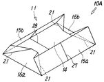
図15は角形蛇篭の第4実施形態を金網の図示を省略して示すもので、この第4実施形態の角形蛇篭10Dは、3つの側面網を備えている点で、上記第1及び第3実施形態の蛇篭10A,10Cと相違している。即ち、この第4実施形態の角形蛇篭10Dは、容体11が、底面網14と、前後の側面網のうち一方の側面網15aと、左右の側面網16a,16bとを有していて、これら左右の側面網16a,16bにそれぞれ折線21が形成されている。この折線21は、前部の側面網15aに連結された側辺側だけに形成されていて、反対側には形成されていない。この蛇篭10Dの上記以外の基本構成や好ましい変形例等については、実質的に上記第1実施形態の蛇篭10Aと同じであるため、主要な同一構成部分に同一符号を付してその説明は省略する。なお、この蛇篭10Dにおいても、必要に応じて上面網が用意される。
【0036】
そしてこの第4実施形態の蛇篭10Dにおいても、左右の側面網16a,16bをそれぞれ上記折線21の位置で斜めに折曲して前部の側面網15aと共に底面網14上に折り重ねることにより、コンパクトに折り畳んで輸送することができるだけでなく、現場での組立作業を、折り重ねた側面網15a,16a,16bを単に立ち上がらせるだけで簡単に行うことができる。
【0037】
なお、図示の例では、左右の側面網16a,16bに折線21が形成されているが、この折線21は、左右の側面網16a,16bに設ける代わりに、図15に鎖線で示すように、それらの間に位置する前部の側面網15aの左右両側に設けることもできる。
【0038】
また、上記第4実施形態の蛇篭10Dは、同様の構成を持つ複数の蛇篭を前後に接続して設置する際に、隣接する蛇篭の接合面間に1枚の側面網15aだけが介在して資材の重複が防止されるようにしたものであるが、同様の考えにより、左右に接続する蛇篭の接合面間に1枚の側面網16a又は16bだけを介在させるようにする場合には、蛇篭を、前後の側面網15a,15bと、左右いずれか一方の側面網16a又は16bとを備えるように構成すれば良く、この場合に折線21は、上記前後の側面網15a,15bにそれぞれ形成されるか、それらの間に位置する側面網16a又は16bに形成される。
【0039】
なお、この第4実施形態の角形蛇篭10Dにおいても、図15に鎖線で示すように、上記底面網14の中間位置に、傾斜する折線21を側部に有する少なくとも1つの仕切面網29を取り付けることができる。
【0040】
図16は角形蛇篭の第5実施形態を金網を省略して示すもので、この第5実施形態の角形蛇篭10Eは、矩形の底面網14と、この底面網14の中間位置に起倒自在に取り付けられた1つ以上の仕切面網29と、上記底面網14の側辺に該仕切面網29と交差する向きに取り付けられた1つの側面網15aとを有している。そして、これらの仕切面網29と側面網15aとは相互に折曲自在なるように連結されていて、上記仕切面網29には、側面網15aに連結された側辺の下端部から斜め上方に向けて傾斜状態に延びる折線21が設けられ、この折線21に沿って斜めに折曲可能なるように構成されている。この蛇篭10Eの上記以外の基本的構成や好ましい変形例等については、実質的に上記第1実施形態の蛇篭10Aと同じであるため、主要な同一構成部分に同一符号を付してその説明は省略する。
【0041】
この角形蛇篭10Eは、図17に示すように、仕切面網29を折線21の位置で折曲することにより側面網15aと共に底面網14上に折り重ね、その状態で現場に輸送したあと、上記仕切面網29と側面網15aとを起立させることにより組み立てる。そして図18に示すように、複数の蛇篭10Eを前後及び左右に配置して、左右の蛇篭間に別形成された共通の側面網16を介在させると共に、後端部に位置する各蛇篭10Eの後面に側面網15bを取り付け、更に、左右両側端部に位置する蛇篭10Eの外側面に側面網16を取り付けることにより、篭マット状に組み立て、内部に石詰めすることにより設置される。この場合、必要に応じて図示しない上面網が取り付けられる。また、蛇篭を段積することもできる。さらに、この角形蛇篭10Eを単独で設置する場合は、別形成された側面網15b及び16a,16bが用意され、開放する3つの側面にこれらの側面網15b及び16a,16bがそれぞれ取り付けられる。
【0042】
なお、図16に示す蛇篭10Eは、仕切面網29の一端側だけに側面網15aを備えているが、同図に鎖線で示すように、仕切面網29の他端側にも側面網15bを設けることができる。この場合には、仕切面網29の両側部に折線21が形成されることは当然である。
【0043】
図19は、折線21を有する側面網15,16又は仕切面網29の変形例を示すもので、この側面網15,16又は仕切面網29は、折線21で区分される各網部分17a,17b,17cを、外周の各辺にそれぞれ骨線31を備えた枠付き網として個別に形成し、これらの網部分の骨線31,31同士を螺旋状連結線のような連結金具32で相互に折曲自在に連結したものである。このような側面網の形態は、図12、図15、図16に示す蛇篭の、一つの折線を有する側面網や仕切面網にも適用できることは言うまでもないことである。
【0044】
なお、上記各実施例では、蛇篭が菱形金網で形成されているが、亀甲金網や溶接金網のようなその他の適宜網材を用いることができることも当然である。
【0045】
【発明の効果】
以上に詳述したように本発明によれば、角形蛇篭を予め容器形など所定の形に組み立てた状態のまま、即ち、各面網を互いに連結した状態のまま、それらを底面網上に折り重ねることができるため、蛇篭を嵩張らないようにコンパクトに折り畳むことができ、現場への輸送が容易で大量の蛇篭を同時輸送することができる。また、現場での蛇篭の組み立ても、折り畳まれた側面網及び仕切面網を単に起立させるだけで、それらを連結する必要がないため、組み立て作業が非常に簡単で一人でも瞬時に行うことができ、蛇篭の設置作業を短時間で効率良く行うことが可能になる。
【図面の簡単な説明】
【図1】本発明に係る角形蛇篭の第1実施形態を示す斜視図である。
【図2】図1の角形蛇篭における容体の一例を示す展開図である。
【図3】図1の角形蛇篭における容体の他例を示す展開図である。
【図4】図1の角形蛇篭における折線付きの側面網の一例を示す正面図である。
【図5】図1の角形蛇篭における折線付きの側面網の他例を示す正面図である。
【図6】図1の角形蛇篭の折り畳み途中の状態を示す金網を省略した斜視図である。
【図7】図1の角形蛇篭の折り畳み後の状態を示す金網を省略した平面図である。
【図8】図1の角形蛇篭の設置例を示す側面図である。
【図9】本発明に係る角形蛇篭の第2実施形態を示す金網を省略した斜視図である。
【図10】図9の角形蛇篭の折り畳み状態を示す金網を省略した平面図である。
【図11】図9の角形蛇篭の他の折り畳み状態を示す金網を省略した平面図である。
【図12】本発明に係る角形蛇篭の第3実施形態を示す金網を省略した斜視図である。
【図13】図12の角形蛇篭の折り畳み状態を示す金網を省略した斜視図である。
【図14】図12の角形蛇篭の設置方法を説明する金網を省略した斜視図である。
【図15】本発明に係る角形蛇篭の第4実施形態を示す金網を省略した斜視図である。
【図16】本発明に係る角形蛇篭の第5実施形態を示す金網を省略した斜視図である。
【図17】図16の角形蛇篭の折り畳み状態を示す金網を省略した平面図である。
【図18】図16の角形蛇篭の設置方法を説明するための平面図である。
【図19】折線を有する側面網又は仕切面網の変形例を示す正面図である。
【図20】従来の角形蛇篭の斜視図である。
【符号の説明】
10A,10B,10C,10D,10E 蛇篭
14 底面網
15a,15b,15 前後の側面網
16a,16b,16 左右の側面網
18 骨線
22 側辺
24 環
25 骨線
29 仕切面網[0001]
TECHNICAL FIELD OF THE INVENTION
The present invention relates to a foldable square gabion, a gabion package, and a method of handling the same.
[0002]
[Prior art]
For example, a square gabion generally called a futon basket or an stone stuffing basket as shown in FIG. 20 is used for revetment work, residential land development work, and the like. This square gabion is usually formed in a hexahedral shape by a rhombus wire mesh, a tortoise wire mesh, a welded wire mesh, and the like, and is placed on the site by filling the inside with debris while opening the upper surface net and then closing the upper net.
[0003]
Such a square gabion generally forms the bottom net 1 and the front and rear side nets 2a and 2b and the left and right side nets 3a and 3b and the top net 4, respectively, and keeps them separated. The partially connected products are transported to the site in a folded state, and the adjacent sides of the respective screen nets are connected to each other by a spiral connection line 5 at the site to be assembled into a container shape. . However, since the connecting line 5 must be wound around the side to be connected while rotating around the central axis, the connecting operation is quite troublesome, and the number of gabions to be installed is tens or hundreds. If the number is too large, it takes a lot of trouble and time to assemble them, resulting in poor work efficiency.
[0004]
Therefore, assembling the above gabion into a container in advance at a factory or the like and transporting it to the site can simplify the on-site assembly work.However, the assembled gabion is very bulky, which is inconvenient for packing and transport, and is therefore inconvenient. Can not be transported.
Such a problem is caused not only by the gabion having all the four side nets 2a, 2b and 3a, 3b as described above, but also by eliminating some side nets, the side nets overlap between adjacent gabions. This is common to a gabion having a special configuration that prevents the occurrence of the gabion.
[0005]
[Problems to be solved by the invention]
The technical problem of the present invention is to prevent the bulky gabion from being bulky and easily transported to the site by configuring the gabion so that it can be folded while being assembled in a predetermined shape. An object of the present invention is to improve the efficiency of the installation work by simplifying the assembly work.
[0006]
[Means for Solving the Problems]
According to the present invention, in order to solve the above-mentioned problems, a rectangular bottom net and at least two side nets adjacent to each other among four side nets are included, and mutually adjacent sides of each net are freely bendable. And one of the adjacent side nets extends obliquely upward from the lower end of the side connected to the other side net. Bone line And this Bone line The folding square gabion which can be bent obliquely along is provided.
[0007]
At least one partition net can be mounted upside down at an intermediate position of the bottom net, in which case the partition net can be folded into a side net whose end intersects the partition net. Connected to and inclined Bone line It is configured so that it can be bent obliquely.
[0008]
Further, according to the present invention, a rectangular bottom net, at least one partition net attached to an intermediate position of the bottom net so as to be able to be turned upside down, and intersects with the partition net on a side of the bottom net. One or two side nets mounted in a direction, these partition nets and the side nets are connected so as to be freely bendable, and the partition nets are connected to the intersecting side nets. Extends obliquely upward from the lower end of the connected side Bone line And this Bone line The folding square gabion which can be bent obliquely along is provided.
[0009]
The square gabion of the present invention having such a configuration, Bone line With side and partition nets Bone line By obliquely bending at the position of, each surface net is folded on the bottom net, and transported to the site in that state, then assembled by erecting the side net and the partition net at the site, and internally It is installed on site by filling it with debris. At this time, an upper surface net is attached to the upper surface as needed. the above Bone line Is desirably substantially 45 degrees.
[0010]
Thus, according to the above-mentioned square gabion, it is possible to fold the gabion in a state assembled in a predetermined shape such as a container shape in advance, that is, in a state where the respective surface nets are connected to each other, on the bottom net. It is possible to fold compactly so as not to be bulky, it is easy to transport to the site, and a large amount of gabions can be transported simultaneously. In addition, the assembly of the gabion on site can be done simply by erecting the folded side nets and the partition nets, and there is no need to connect them. It can be carried out.
[0011]
In the square gabion of the present invention, Bone line Is a net with Bone line Are divided into a plurality of net portions, and these net portions are Bone line Are foldably connected to each other.
[0012]
The adjacent sides of each surface mesh are one Or two It is desirable that they are connected to each other via a bone line.
[0013]
Further, according to the present invention, the square gabion, while the respective screens are interconnected, Bone line With a screen net Bone line A gabion package is provided, wherein the package is folded obliquely at the position shown in FIG.
[0014]
Furthermore, according to the present invention, the above-mentioned square gabion, while the respective screen nets are interconnected, Bone line With a screen net Bone line A gabion handling method, characterized in that it is folded on the bottom net by being bent obliquely at the position, transported to the site in that state, and then assembled by erecting the surface nets at the site. Is done.
[0015]
BEST MODE FOR CARRYING OUT THE INVENTION
FIG. 1 shows a first embodiment of a square gabion according to the present invention. This square gabion 10A has a container 11 in the shape of a rectangular container having an open upper surface, and an upper surface net 12 for closing the upper surface if necessary. The container 11 and the upper surface net 12 are formed by a rhombus wire net formed by sequentially connecting a plurality of column lines bent in a flat spiral shape.
[0016]
The container 11 is composed of a rectangular bottom net 14, a pair of front and rear rectangular side nets 15a and 15b, and a pair of right and left rectangular side nets 16a and 16b. , 15a, 15b, 16a, and 16b are assembled in a rectangular container shape in advance by connecting mutually adjacent sides so as to be bendable. In this case, as shown in FIG. 2, each of the surface nets 14, 15a, 15b, 16a, 16b is individually formed and connected to each other by a suitable connecting means such as a bone line 18, or As shown in FIG. 3, the bottom net 14 and the front and rear side nets 15a, 15b are formed integrally, and the left and right side nets 16a, 16b are formed individually, and they are mutually connected by the same appropriate connecting means. They may be connected.
[0017]
In the example shown in FIG. 2, the bottom net 14 and the front and rear side nets 15a, 15b are provided in common with one bent portion 19a of the column line 19 located at the adjacent end of each of the nets 14, 15a, 15b. By inserting the bone lines 18, they are connected to each other, and the bottom net 14 and the left and right side nets 16 a and 16 b insert one common bone line 18 into the ring 19 b formed at the end of the row line 19. By doing so, the side edges of the adjacent side nets 15a and 16a and the adjacent side nets 15b and 16b are connected to the bent portion 19a of the column line 19 located at the end and the ring 19b formed at the end of the column line. Are connected to each other by inserting a single common bone line 18 into them. Further, in the example shown in FIG. 3, the same as in FIG. 2 except that one bone line 18 is inserted into the boundary between the integrally formed bottom net 14 and the front and rear side nets 15a and 15b. The screens 14, 15a, 15b, 16a, 16b are connected by the following method. That is, in these examples, the mutually adjacent sides of each of the surface nets 14, 15a, 15b, 16a, 16b are connected to each other by one bone line 18.
[0018]
Note that the words "front and rear" and "left and right" are used in the description of the side net, but this is an expression used for convenience in describing the illustrated gabion, and The installation direction is not specified.
In addition, the side nets 15a, 15b and 16a, 16b are simply denoted by reference numerals "15" or "16" when it is not necessary to distinguish them.
[0019]
The left and right side nets 16a and 16b of the container 11 are formed with fold lines 21 for allowing these side nets to be bent obliquely. The fold line 21 diagonally connects the lower end of the side 22 connected to the adjacent side nets 15a and 15b and the middle of the upper side 23, as shown in detail in FIG. 4 or FIG. The column line 19 forming the side nets 16a and 16b is divided at the position of the fold line 21, and a ring 24 is formed at each of the divided line ends. The folded lines 21 are formed by connecting the lines 19 to each other. In the example shown in FIG. 4, the bent lines 21 are formed at positions where the bent portions 19a of the respective column lines 19, 19 should engage with each other. In the example shown in FIG. The folding line 21 is formed between the bent portions 19a and 19a. However, depending on the spiral pitch of the column line 19, the inclination angle of the fold line 21, and the like, the fold line 21 is inclined with respect to the row of the bent portions 19a of the column line 19 as shown by the chain line in FIG. , May be provided so as to straddle this bent part row. The inclination angle θ of the folding line 21 is desirably substantially 45 degrees, but may be slightly larger or smaller than 45 degrees.
[0020]
Further, the upper side 23 of the side nets 16a, 16b is divided into two or three line portions by the formation of the fold lines 21, and these line portions are connected to bend freely. That is, as shown in FIGS. 4 and 5, for example, the length L of the side nets 16a and 16b is larger than twice the height H, and the folding line 21 is formed on both sides of the side nets 16a and 16b by a 45-degree inclination angle. In this case, since the upper ends of the two fold lines 21 intersect with the upper side 23 at positions separated from each other, the upper side 23, that is, the bone line 26 is divided into three line portions 26a, 26b, 26c, and these line portions Are bendably connected to each other. On the other hand, when the length L of the side nets 16a and 16b is approximately twice the height H, the upper ends of these fold lines 21 intersect each other at the center of the upper side 23, so that the bone line 26 is 2 Is divided into two line parts.
[0021]
Therefore, the side nets 16a and 16b having the fold lines 21 are formed by the fold lines 21 into a plurality of net portions, that is, net portions 17a and 17b forming a triangular shape on both sides, and a trapezoidal or triangular net between them. The mesh portion is divided into a portion 17c and these mesh portions are connected to each other by a bone line 26 at the position of the folding line 21 so as to be freely bendable.
[0022]
Reference numeral 27 in FIG. 1 denotes a reinforcing line vertically attached to an intermediate position between the front and rear side nets 15a and 15b in order to maintain shape retention, and 28 denotes a reinforcing line for reinforcing the bottom net 14. is there.
[0023]
The rectangular gabion 10A having the above-described configuration is a state in which the container 11 is assembled in a box shape in advance as shown in FIG. 1, in other words, the adjacent sides of the adjacent side nets 15a, 15b, 16a, 16b are connected to each other. 6, the left and right side nets 16a and 16b provided with the fold line 21 are bent obliquely inward at the position of the fold line 21, as shown in FIG. At the same time, the front and rear side nets 15a and 15b are folded over on the bottom net 14 by falling on the front side nets 15a and 15b, thereby being folded flat as shown in FIG. Then, in this state, one or more packages are packed together and transported to the site as a gabion package, and then the packing is unpacked at the site, and the side nets 15a, 15b, 16a, 16b are raised to form a figure. As shown in FIG. 1, it is assembled in a box shape, a required number is arranged in a predetermined place, earth and the like are filled therein, and the upper surface net 12 is closed to be installed at the site. In this case, each gabion 10A is not necessarily installed with the front and rear side nets 15a and 15b facing the front and rear of the installation location, and naturally it is installed with the left and right side nets 16a and 16b facing front and rear. possible.
[0024]
The attachment of the upper surface net 12 can be performed by appropriate means. However, even when a spiral connection line is used, compared with the conventional construction method using a spiral connection line for connection of all the surface nets, the use of the connection method is less. Since it is limited only to the attachment of the upper net 12, the number and time required for the connection are greatly reduced. For example, in a case where a plurality of cascades are stacked vertically, a top network of the lower cascade can be omitted by covering the upper surface of the lower cascade with the upper cascade.
[0025]
In addition, the gabion 10A may be continuously installed at a place where the inclination angle changes in the middle, for example, as shown in FIG. 8, in which an inclined slope 20a and a horizontal road shoulder 20b are connected. In such a case, the gabion 10A installed at the corner is formed such that the side nets 15a, 15b or 16a, 16b facing the corner are inclined. By forming the above-mentioned fold lines 21 on the side nets 15a, 15b or 16a, 16b, the fold can be made freely.
[0026]
Thus, according to the above-mentioned square gabion 10A, these are assembled in a container shape in advance, that is, in a state in which adjacent sides of adjacent side nets 15a, 15b, 16a, 16b are connected to each other. By folding each side net on the bottom net 14, it is possible to fold it compactly so as not to be bulky, to easily transport it to the site, and to transport a large number of gabions simultaneously. In addition, assembling at the site, the folded side nets 15a, 15b, 16a, and 16b only need to be made to stand up, so that the assembling work is very simple and can be performed by one person instantaneously. It can be performed efficiently in a short time.
[0027]
In the illustrated embodiment, the fold line 21 is provided on the shorter side nets 16a and 16b, but the fold line 21 may be provided on the longer side nets 15a and 15b. Is natural.
[0028]
FIG. 9 shows the second embodiment of the square gabion without a wire mesh. The square gabion 10B of the second embodiment has a partition net 29 for partitioning the inside into a plurality of stone-packed areas. This is different from the square gabion 10A of the first embodiment. That is, in the square gabion 10B of the second embodiment, the partition net 29 is arranged at an intermediate position of the bottom net 14 in parallel with the left and right side nets 16a and 16b, and the bottom of the partition net 29 is set to the bottom net 14B. And both sides are connected to the front and rear side nets 15a and 15b, respectively, so as to be freely bent. As a method for connecting the partition surface net 29 to the other surface nets 14, 15a, 15b, the same method as the method for connecting the bottom net 14 and the side nets 15a, 15b, 16a, 16b can be used. However, other methods may be used. Like the left and right side nets 16a and 16b, the partitioning net 29 has a fold line 21 inclined obliquely upward from the lower end of the side connected to the side nets 15a and 15b. It is configured so that it can be bent obliquely at the position of the folding line 21. Since the gabion 10B is substantially the same as the gabion 10A of the first embodiment described above except for the configuration other than the above, the necessity of the upper surface net, or a preferred modification, the same reference numerals are given to the same components. The description is omitted.
[0029]
Therefore, also in the square gabion 10B of the second embodiment, as shown in FIG. 10, the partition net 29 is bent at the position of the folding line 21 in the same manner as the left and right side nets 16a and 16b, so that each side surface is bent. It can be folded together with the nets 15a, 15b and 16a, 16b on the bottom net 14.
[0030]
Instead of providing the folding lines 21 on the left and right side nets 16a and 16b as described above, the folding lines 21 may be provided on the front and rear side nets 15a and 15b as shown by chain lines in FIG. The square gabion 10B is folded as shown in FIG.
In the illustrated example, one partition net 29 is provided, but it goes without saying that a plurality of partition nets 29 can be provided according to the length of the gabion.
[0031]
FIG. 12 shows a third embodiment of a square gabion without a wire net. The square gabion 10C of the third embodiment has only two adjacent side nets 15a and 16a as side nets. , And is different from the gabion 10A of the first embodiment having four side nets 15a, 15b, 16a, 16b of front, rear, left and right. That is, in the square gabion 10C of the third embodiment, the container 11 is configured such that the bottom net 14, the one side net 15a of the pair of front and rear side nets, and the one side net 16a of the pair of right and left side nets. A folding line 21 is formed on one of the two side nets 15a, 16a. The folding line 21 is formed only on the side 22a connected to the side net 15a, and is not formed on the other side 22b. The basic structure and preferred modified examples of the gabion 10C other than the above are substantially the same as those of the gabion 10A of the first embodiment, and thus the same reference numerals are given to the same main components, and description thereof will be omitted. I do.
Although not shown, the upper net 12 is also prepared for the gabion 10C as required.
[0032]
As shown in FIG. 13, the square gabion 10C folds and packs the side nets 15a and 16a on the bottom net 14, and transports the net to the site in that state. Then, as shown in FIG. As shown in FIG. 14, a plurality of similarly configured gabions 10C are arranged in front and rear and left and right and connected to each other by appropriate means, as shown in FIG. By attaching the side nets 15b and 16b individually formed to the gabion 10C to be assembled, a plurality of gabions 10C are assembled into an integrated basket mat shape, and the interior is filled with earth and stone and the top net is attached. Is done. No fold lines are formed on the side net 16a.
[0033]
Thus, the gabion can be installed in a state where only one side net 15a, 16a is interposed between the joining surfaces of the two adjacent gabions 10C, 10C. Can be planned. In this case, the upper surface net may be individually attached to each gabion 10C, or an upper surface net having a length corresponding to the vertical or horizontal gabion column may be attached, or a plurality of vertical or horizontal gabion columns may be attached. The gabion can be used as one unit, and an upper surface net having a width corresponding to each unit can be attached to each unit. Further, for example, in the case where a plurality of cascades are vertically stacked, the upper surface of the lower cascade can be omitted by covering the upper surface of the lower cascade with the upper cascade.
[0034]
In the square gabion 10C according to the third embodiment, as shown by the chain line in FIGS. 29 can be attached.
When the square gabion 10C is independently installed, the above-described side nets 15b and 16b may be attached to two open side surfaces thereof.
[0035]
FIG. 15 shows a fourth embodiment of a square gabion without arranging a wire mesh. The square gabion 10D of the fourth embodiment has three side nets. It is different from the gabions 10A and 10C of the embodiment. That is, in the square gabion 10D of the fourth embodiment, the container 11 has a bottom net 14, one of the front and rear side nets 15a, and left and right side nets 16a and 16b. Fold lines 21 are formed on the left and right side nets 16a and 16b, respectively. The fold line 21 is formed only on the side connected to the front side net 15a, and is not formed on the opposite side. Since the basic structure and preferred modified examples of the gabion 10D other than the above are substantially the same as those of the gabion 10A of the first embodiment, the same reference numerals are given to the same main components, and the description is omitted. I do. In addition, also in this gabion 10D, an upper surface net is prepared as needed.
[0036]
Also in the gabion 10D of the fourth embodiment, the left and right side nets 16a and 16b are each bent obliquely at the position of the folding line 21 and folded on the bottom net 14 together with the front side net 15a. Not only can it be compactly folded and transported, but also the on-site assembling operation can be easily performed simply by standing up the folded side nets 15a, 16a, 16b.
[0037]
In the illustrated example, the fold lines 21 are formed on the left and right side nets 16a and 16b. Instead of providing the fold lines 21 on the left and right side nets 16a and 16b, as shown by chain lines in FIG. They may be provided on the left and right sides of the front side net 15a located between them.
[0038]
In the gabion 10D of the fourth embodiment, when a plurality of gabions having the same configuration are connected to each other before and after installation, only one side net 15a is interposed between the joining surfaces of the adjacent gabions. Although the overlapping of the materials is prevented, the same idea is applied to the case where only one side net 16a or 16b is interposed between the joining surfaces of the gabions connected to the left and right. May be configured to include the front and rear side nets 15a and 15b and the left or right side net 16a or 16b. In this case, the folding line 21 is formed on the front and rear side nets 15a and 15b, respectively. Or formed on the side net 16a or 16b located therebetween.
[0039]
Also in the square gabion 10D of the fourth embodiment, as shown by a chain line in FIG. 15, at least one partition surface net 29 having an inclined fold line 21 on the side is attached to an intermediate position of the bottom net 14. be able to.
[0040]
FIG. 16 shows a fifth embodiment of a square gabion without a wire net. A square gabion 10E according to the fifth embodiment has a rectangular bottom net 14 and an intermediate position between the bottom net 14 so as to be free to fall. It has one or more partition nets 29 attached, and one side net 15a attached to the side of the bottom net 14 in a direction crossing the partition nets 29. The partition net 29 and the side net 15a are connected to each other so as to be freely bendable. The partition net 29 is obliquely upward from the lower end of the side connected to the side net 15a. A fold line 21 is provided which extends in an inclined state toward, and can be bent obliquely along the fold line 21. The basic structure and preferred modified examples of the gabion 10E other than the above are substantially the same as those of the gabion 10A of the first embodiment. Omitted.
[0041]
As shown in FIG. 17, this square gabion 10E is folded on the bottom net 14 together with the side net 15a by bending the partition net 29 at the position of the fold line 21, and after being transported to the site in that state, The partition net 29 and the side net 15a are assembled by standing up. Then, as shown in FIG. 18, a plurality of gabions 10E are arranged in front and rear and left and right, a common side net 16 formed separately between the left and right gabions is interposed, and each of the gabions 10E located at the rear end is formed. By attaching the side net 15b to the rear surface, and further attaching the side net 16 to the outer side surface of the gabion 10E located at both left and right end portions, the gabion is assembled into a mat shape and packed inside by stone. In this case, a top net (not shown) is attached as needed. Gabions can also be stacked. Furthermore, when this square gabion 10E is installed alone, separately formed side nets 15b, 16a, and 16b are prepared, and these side nets 15b, 16a, and 16b are attached to three open side surfaces, respectively.
[0042]
The gabion 10E shown in FIG. 16 is provided with a side net 15a only at one end of the partition net 29, but as shown by a chain line in FIG. Can be provided. In this case, it is natural that the folding lines 21 are formed on both sides of the partition surface net 29.
[0043]
FIG. 19 shows a modified example of the side nets 15 and 16 or the partition net 29 having the fold lines 21. The side nets 15 and 16 or the partition net 29 are formed by the net portions 17a and 17a divided by the fold line 21. 17b and 17c are individually formed as framed nets each having a skeleton 31 on each side of the outer periphery, and the skeletons 31 of these net portions are mutually connected by a connection fitting 32 such as a spiral connection line. It is connected to bend freely. It is needless to say that such a form of the side net can be applied to the side net or the partition net having one folding line of the gabion shown in FIGS. 12, 15, and 16.
[0044]
In each of the above embodiments, the gabion is formed of a rhombus wire mesh, but it is obvious that other appropriate mesh materials such as a turtle wire mesh or a welded wire mesh can be used.
[0045]
【The invention's effect】
As described in detail above, according to the present invention, the square gabions are assembled in a predetermined shape such as a container in advance, that is, they are folded on the bottom net while the nets are connected to each other. Since the gabions can be stacked, the gabions can be folded compactly so as not to be bulky, and can be easily transported to the site and a large number of gabions can be transported simultaneously. Also, as for the assembly of the gabion on site, the folded side net and the partition net are simply raised and there is no need to connect them, so the assembling work is very easy and one person can do it instantly. In addition, the gabion installation work can be performed efficiently in a short time.
[Brief description of the drawings]
FIG. 1 is a perspective view showing a first embodiment of a square gabion according to the present invention.
FIG. 2 is a development view showing an example of a container in the square gabion of FIG.
FIG. 3 is a developed view showing another example of the container in the square gabion of FIG. 1;
FIG. 4 is a front view showing an example of a side net with a folding line in the square gabion of FIG. 1;
FIG. 5 is a front view showing another example of the side net with fold lines in the square gabion of FIG. 1;
FIG. 6 is a perspective view of the square gabion shown in FIG. 1, showing a state in which the gabion is being folded, without a wire mesh;
FIG. 7 is a plan view of the square gabion of FIG. 1 after folding, showing a state after folding;
FIG. 8 is a side view showing an example of installation of the square gabion of FIG. 1;
FIG. 9 is a perspective view of a square gabion according to a second embodiment of the present invention, in which a wire mesh is omitted.
FIG. 10 is a plan view showing the folded state of the square gabion shown in FIG. 9, in which a wire mesh is omitted.
11 is a plan view of the square gabion shown in FIG. 9 in another folded state, in which a wire mesh is omitted.
FIG. 12 is a perspective view of a third embodiment of a square gabion according to the present invention, in which a wire mesh is omitted.
FIG. 13 is a perspective view showing the folded state of the square gabion shown in FIG. 12, in which a wire mesh is omitted.
FIG. 14 is a perspective view in which a wire mesh is omitted for explaining a method for installing the square gabion of FIG. 12;
FIG. 15 is a perspective view of a square gabion according to a fourth embodiment of the present invention, in which a wire mesh is omitted.
FIG. 16 is a perspective view of a square gabion according to a fifth embodiment of the present invention, in which a wire mesh is omitted.
FIG. 17 is a plan view showing the folded state of the square gabion shown in FIG. 16 with a wire mesh omitted.
FIG. 18 is a plan view for explaining a method of installing the square gabion of FIG.
FIG. 19 is a front view showing a modified example of a side net or a partition net having a folding line.
FIG. 20 is a perspective view of a conventional square gabion.
[Explanation of symbols]
10A, 10B, 10C, 10D, 10E Gabion
14 Bottom net
15a, 15b, 15 Front and rear side nets
16a, 16b, 16 Left and right side nets
18 bone line
22 sides
24 rings
25 bone line
29 Partition net