JP3553383B2 - Wireless transmitting / receiving method and wireless transmitting / receiving system - Google Patents
Wireless transmitting / receiving method and wireless transmitting / receiving system Download PDFInfo
- Publication number
- JP3553383B2 JP3553383B2 JP21495898A JP21495898A JP3553383B2 JP 3553383 B2 JP3553383 B2 JP 3553383B2 JP 21495898 A JP21495898 A JP 21495898A JP 21495898 A JP21495898 A JP 21495898A JP 3553383 B2 JP3553383 B2 JP 3553383B2
- Authority
- JP
- Japan
- Prior art keywords
- signal
- reception
- receiving
- wideband signal
- antenna
- Prior art date
- Legal status (The legal status is an assumption and is not a legal conclusion. Google has not performed a legal analysis and makes no representation as to the accuracy of the status listed.)
- Expired - Fee Related
Links
Images


Description
【0001】
【発明の属する技術分野】
本発明は、BS、CSなどの広帯域信号の無線送受信方法に関し、特に、ミリ波を用いた屋内、構内での広帯域信号を無線送受信する方法に関する。
【0002】
【従来の技術】
通常、移動体無線通信では、マルチパスによるフェージングの影響を避け安定した受信を行うために、ダイバーシチ受信が考案されており、さらに、複数チャンネルの受信のために、特開平5−29995号公報に示されているように、チャネルの数だけ受信強度比較回路や、アンテナ切り替え回路を用いる方法が考案されている。
【0003】
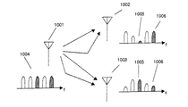
特開平5−29995号公報に示されている多チャンネルの信号を含む多数の電波を一括受信する装置として、本明細書願では衛星放送など放送通信に適用した場合について説明する。図11に従来技術の無線送受信装置を示す。
【0004】
周波数軸上に各チャンネルが配置された多チャンネルの送信信号1004が、送信アンテナ1001から送信される。空間伝送におけるマルチパスによるフェージングの影響で、一部のチャンネルで著しく強度が低下するため、複数のアンテナ1002、1003で受信した場合、各チャンネルで強度の大きいアンテナを選択して受信を行う(ダイバーシチ受信)。たとえば、受信信号のチャンネル1005では、チャンネル1005の強度の大きいアンテナ1003を、受信信号のチャンネル1006ではチャンネル1006の強度の大きいアンテナ1002を独立して選択する。その結果、複数のチャンネルで安定した受信が可能である。
【0005】
【発明が解決しようとする課題】
送信信号1004の各チャンネルの情報がTV映像信号であり、ブラウン管にマルチ画面で映像を表示するためには、その数だけのアンテナ1002、1003の選択回路が必要となることになる。裏番組だけを表示するならば2個、16分割の画面で複数のチャンネルを表示させるためには16個が必要になる。また、あるチャンネルがデジタル信号であり、あるチャンネルがアナログ信号であるように、チャンネル間において送信方式が異なる場合を考慮すると、各送信方式毎に対応したアンテナ切り替え回路が必要となり、非常に複雑なシステムとなる。
【0006】
上記の方法では、チャネルの数だけのダイバーシチ回路が必要となることが避けられず、特開平5−29995号公報においても、その回路を減らすために工夫をしているが、やはり、チャンネルの数だけの受信強度比較回路と、アンテナ切り替え回路が必要になっている。更に、このシステムの場合、ダイバーシチ回路は受信チャンネルを切り替えた場合にダイバーシチ回路も追随して、評価周波数を切り替える必要があり、受信システム全体がダイバーシチ回路専用のシステムである必要がある。
【0007】
本発明の目的は、チャンネル数だけのダイバーシチ回路を必要とすることなく、多チャンネルを含む広帯域信号を受信できる無線送受信方法を提供することを、目的とする。
【0008】
【課題を解決するための手段】
本発明の第1無線送受信方法は、多チャンネルを含む広帯域信号を送信機から受信アンテナを介して受信機に送受信する経路を複数有する無線送受信方法であって、マルチパスによって前記広帯域信号が重畳されていない経路を選択することを特徴する。
【0009】
本発明の第2無線送受信方法は、前記広帯域信号がミリ波帯域信号であることを特徴とする。
【0010】
本発明の第3無線送受信方法は、前記広帯域信号に複数の周波数上で同じ信号強度の基準信号を挿入して送信し、受信した複数の前記基準信号の信号強度差が小さい経路を選択することによって、前記マルチパスによって広帯域信号が重畳されていない経路を選択することを特徴とする。
【0011】
本発明の第4無線送受信方法は、前記広帯域信号に一定信号強度の基準信号を周波数スイープして送信し、受信した前記基準信号のスイープ中の信号強度差が小さい経路を選択することによって、前記マルチパスによって広帯域信号が重畳されていない経路を選択することを特徴とする。
【0012】
本発明の第5無線送受信方法は、前記広帯域信号と異なる周波数上に、信号帯域内のスペクトル情報を挿入して送信し、受信した広帯域信号の周波数分布と前記信号帯域内のスペクトル情報とを比較して前記広帯域信号の周波数分布と前記信号帯域内のスペクトル情報との差が小さい経路を選択することによって、前記マルチパスによって広帯域信号が重畳されていない経路を選択することを特徴とする。
【0013】
また、本発明の第6無線送受信方法は、第3〜5無線送受信方法のいずれかの前記マルチパスによって広帯域信号が重畳されていない経路のうち、受信した前記基準信号の強度が大きい経路を選択することを特徴とする。
【0014】
また、本発明の第7無線送受信方法は、送信開始時、又は受信開始時に前記基準信号を第3〜5無線送受信方法のいずれかで前記マルチパスによって広帯域信号の重畳していない経路を複数選択し、適宜広帯域信号と異なる周波数に基準信号を挿入することによって、受信された前記基準信号の強度の大きい経路を選択することを特徴とする。
【0015】
また、本発明の第8無線送受信方法は、前記アンテナが可動式であり、第3〜7無線送受信方法のいずれかで前記アンテナの方向を選択することを特徴とする。
【0016】
本発明の第9無線送受信方法は、前記アンテナがフェーズアレイアンテナであることを特徴とする。
【0017】
本発明の第10無線送受信方法は、前記アンテナの配置が角度ダイバーシチであることを特徴とする。
【0018】
本発明の第11無線送受信方法は、前記アンテナの配置が位置ダイバーシチであることを特徴とする。
【0019】
本発明の第12無線送受信方法は、前記アンテナの配置が周波数ダイバーシチであることを特徴とする。
【0020】
また、本発明の第13無線送受信方法は、前記送信機が指向性アンテナを備えていることを特徴とする。
【0021】
本発明の第14無線送受信方法は、前記送信機が複数あるいは中継器を備えていることを特徴とする。
【0022】
【発明の実施の形態】
(実施例1)
図1に本発明に係る無線送受信方法の1実施例を示す。ここでは、BS、CS放送の全チャンネルを同時に送受信するシステムの例について説明する。
【0023】
チャンネルの数が多いので全チャンネルをひとつの超広帯域信号(60GHz〜61.5GHz)105として示している。送信機では、BS、CS放送を受信し、一般の集合住宅で利用されているブロックコンバータを用い、約1〜1.5GHzのIF周波数に変換したものを、ミリ波(60〜61.5GHz)にアップコンバートして送信アンテナ101から超広帯域信号105を送信している。超広帯域信号105は、複数の受信アンテナ102、103、104で受信されている。
【0024】
この時、本実施例では以下のような受信状況になっているものとする。受信アンテナ102ではマルチパスのため、一部の信号に著しい強度の低下を生じている受信信号106となっている。受信アンテナ103では送信アンテナからの直接波のみを受信して、各チャンネルに強度差が無い受信信号107となっている。受信アンテナ103では、反射波を受信しているため、受信強度は低いがマルチパスが無いため受信強度が著しく低いチャンネルがない受信信号108となっている。この場合、受信アンテナ103を選択することで良好な受信が可能となる。また、送受信アンテナ間を人が遮るなどして受信アンテナ103の受信感度が低下した場合(シャドウイング)に、受信アンテナ104に切り替えることで安定した受信が可能となる。具体的に受信アンテナ103、104を選択するための方法を次に述べる。
【0025】
図2(a)に実施例1での最適な受信アンテナを選択するため方法について示す。超広帯域信号206とは別の周波数とした複数の信号強度の同じ基準信号205を送信アンテナ201から同時に送信する。受信した時の複数の基準信号の信号強度が異なる場合には、マルチパスのある経路と判断する。本実施例では、受信アンテナ202で受信された基準信号207の一部の信号強度に強度の小さいものを含む時には、一部の信号に著しい強度の低下が生じた受信信号208となっていることが分かる。従って、受信アンテナ202で受信した場合、複数の基準信号207のうち最低信号強度のものが受信感度を下回っていなくとも、実際の受信映像信号の全て周波数の中には大きく受信感度が低下しているチャンネルを含む受信信号208となるので、一定以上の差があるものはマルチパスを含む信号として排除する。
【0026】
また、受信した複数の基準信号の信号強度の同じアンテナにおいては、基準信号の強度が大きい順に受信アンテナを選択する。本実施例では、受信アンテナ203、204の場合には、受信された基準信号209、211が同じであり、受信信号210、212ではマルチパスによる影響を受けていない。この場合には、受信した基準信号の信号強度の大きい受信アンテナ203を選択する。尚、受信アンテナ203への経路は、直接送信アンテナから受信アンテナに直接送受信された経路であるシングルパスとなる例であり、受信アンテナ204への経路は、送受信途中で反射された経路となった例である。
【0027】
次に、図2(b)では、図2(a)で説明した無線送受信方法に用いる受信装置の回路例を示す。受信アンテナ231で受信した信号は、RFアンプ232で増幅され、ミキサ234に入り、ローカル発振器233からの周波数とミキシングされIF周波数帯の信号となり、フィルター236によって基準信号が取り出され、基準信号比較回路237に入る。図2(b)では3個のアンテナの例をあげており、同じ構成の回路が3個並列しており、各々、基準信号比較回路に入力されている。基準信号比較回路237では、基準信号に基づいて最も適したアンテナを選択し、スイッチ238をON、OFFする。ミキサー234からの出力はフィルター235にも入力され、フィルター235では広帯域信号が出力され、スイッチ238を通ってIF信号出力端子239に出力される。IF信号出力端子には、通常のBS、CS放送のIF信号受像装置を接続すればどのチャンネルも受像装置のチャンネル選択のみで選択可能である。また、複数台の受像機を接続して、独立に別々のチャンネルを選択することも可能である。
【0028】
本実施例では、受信アンテナを複数個備えることによって、その中から最適なアンテナを選び出すこととしたが、1つの受信アンテナを可動可能とし、その受信アンテナの最適な位置を決定するのに本発明の方法を用いても構わない。
【0029】
(実施例2)
図3に、実施例1とは異なるアンテナ選択方法の例を示す。
超広帯域信号306とは別の周波数上で周波数スイープした基準信号305を送信アンテナ301から送信する。受信した基準信号の信号強度がスイープ中に変化した場合は、マルチパスのある経路と判断し、その経路に用いる受信アンテナを排除する。本実施例では受信アンテナ302で受信した基準信号のスイープ中に信号強度が変化しており、一定値を越える変化があるとして受信アンテナ302は排除される。ここで、一定値を越える変化とは、使用環境などによって使用者が適宜決定する値である。
【0030】
また、受信した基準信号がスイープ中に変化しない場合には、基準信号強度の大きい経路を選択する。本実施例の場合には、受信アンテナ303で受信された基準信号309と受信アンテナ304で受信された基準信号311との信号強度を比較して、信号強度の大きい受信アンテナ303の経路を選択する。
【0031】
また、基準信号の強度が変化しなかった経路において、基準信号の強度が大きい順にアンテナを選択する。従って、本実施例では、受信された基準信号強度の大きい受信アンテナ303の経路が選択される。
【0032】
本実施例のように周波数スイープし、その変化に基づいて経路を選択する場合には、サンプリング周波数が実施例1の場合より多くできるので、マルチパスを見つけるのに非常に効果的である。
【0033】
より確実にマルチパス経路を排除する方法について、図4に示す。図4では、信号周波数帯域401より周波数帯域の同じ若しくは広い周波数帯域で基準信号のスイープ402を行っている。信号周波数帯域401より広いスイープ402を行うことで確実にフェージングの有無をチェックすることができる。
【0034】
(実施例3)
図5に、実施例1、2のような一定の基準信号とは異なり、実際の映像等の信号を使ってマルチパスの有無を調べる方法を示す。
【0035】
実際の映像信号、音声信号などは異なる強度、帯域幅、そして、それらが時間的に変化しているので、その様子を簡略化して超広帯域信号507に示した。本実施例の超広帯域信号507では、ある帯域信号506(矢印の付された帯域信号)を含む3つの帯域からなっている。実際の超広帯域信号507とは別に帯域信号内のスペクトル情報505を付加し、送信アンテナ501から送信する。
【0036】
ここで、信号帯域内のスペクトル情報505は、超広帯域信号507の強度情報を含んでおり、受信機で実際に受信した信号と、帯域信号内のスペクトル情報とを比べ、マルチパスの有無を調べることでマルチパスの有無を判別する。ここでは、帯域信号内のスペクトル情報505として、超広帯域信号507の信号強度を周波数軸上でスイープした信号をAM変調して送信する例である。強度情報信号は現在のスイープ部分(帯域信号506)と同じ強度となるように送信される。
【0037】
帯域信号内のスペクトル情報505と、実際の信号(帯域信号506)は異なる周波数なので受信アンテナ502のようにマルチパスがあると受信された帯域信号内のスペクトル情報505からの予想される各周波数での信号強度(点線)と実際の強度(実線)が異なる。受信アンテナ503、504では、シングルパスなのでスペクトル情報と、実際の信号(帯域信号506)は同じ強度となる。
【0038】
この方法では実際のチャンネル周波数全体でのマルチパスの有無がチェックでき、しかも、比較用の信号帯域内のスペクトル情報を追加するだけでいいので、使用する周波数帯域がほとんど増加無く実現することができる。
【0039】
当然、帯域信号内のスペクトル情報505だけでなく、周波数スイープの情報信号を入れてもよく、AM変調でなくとも可能である。ここで、AM変調を用いたのは、反射で信号強度が低下した場合(受信アンテナ504)でも強度信号情報も同様に強度が低下するので直接比較できるメリットがあるためである。この方法は、一定の基準信号で周波数スイープするのとは異なり、使用中の全周波数を常にチェックすることが可能である。
【0040】
(実施例4)
本実施例では、本発明に係る実際の運用について説明する。最も簡単には、送信開始時、又は受信開始時、一度、周波数スイープでマルチパスの有無をチェックする。図6(a)に周波数スイープの状態を示す。この時に、最も適したアンテナを選択し、以後最も適したアンテナ使用する方法が可能である。図6(b)には、広帯域信号を示す。この場合は、非常に受信状態のよい場所で、受信途中にシャドウイング、マルチパスの変化等が起こらない場合に有効である。ここでは、周波数スイープによる方法としたが、実施例3で示したスペクトル情報を用いても構わない。
【0041】
また、人間の移動があり、シャドウイングがある場合は、図7のように送信開始時、又は受信開始時(図7(a)にこの時送信する周波数スイープを示す)に、一度、周波数スイープでマルチパスの有無をチェックし、適した複数のアンテナを選択する。以後、一定期間おきに先述した基準信号を用いて、基準信号604の強度の強いものを使用する方法が可能である。この様子を図7(b)に示す。この場合には、受信信号601が受信できるようにアンテナを選択する。次に、図7(c)の様に、シャドウイングで受信信号605の強度が低下したら、この時に信号強度の大きい基準信号608に基づいて、別の受信信号606が受信できるアンテナを使用する。図7に示すような運用を行う場合は、人間が主に電波の吸収体であり、反射がほとんど無視できるミリ波帯の通信に適している。
【0042】
ミリ波通信の場合でも、ドア、窓、ブラインド、他、ミリ波を反射する大きな物が移動する場合は、マルチパスの新たな経路の発生が無視できなくなるので、それらのものに電波吸収体を取り付けるとよい。
【0043】
この方法は、最初にマルチパスの評価をした後は、基準信号強度だけで評価するので構成が簡単にできる。上記の例では、周波数スイープでマルチパスの影響を評価したが、実施例1、3のような方法を用いてもよい。
【0044】
本実施例では、送信開始時又は受信開始時にマルチパスのチェックを行うとしたが、使用環境によっては、本発明の送受信方法を設置したときのみマルチパスのチェックを行ってもよい。あるいは、利用者が受信状況から必要と感じたときに行ってもよい。
【0045】
(実施例5)
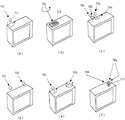
実際のアンテナの配置、システムの構成例を示す。図8(a)は、送信開始時、又は受信開始時に指向性アンテナ方向を前述の方法で評価し、アンテナの方向を決定する例である。手動でアンテナ711方向を変え、良好なアンテナ方向701の場合に光、音等で知らせることで適切なアンテナ方向を選択する。当然、自動でアンテナを駆動させてもよい。
【0046】
図8(b)は、フェーズドアレイアンテナ712を使った同様の例である。可動部分が無いので非常に高速に方向を変化させることができる。
【0047】
図8(c)は、複数の指向性アンテナを前述の方法で評価し、実施例3、4の方法を用いて方向701、702、703、704を切り替えて利用する例である。角度ダイバーシチに相当するである。より好ましくは、個々のアンテナが図8(a)のように可動であり、好ましい方向を向いた上で相互に選択できるともっとも効率的である。
【0048】
図8(d)は、位置ダイバーシチでの同様の例である。ミリ波の場合はシャドウイング(主に人体による)で致命的な受信妨害を引き起こすので、図8(e)のように角度ダイバーシチとの組み合わせが更にに効果的となる。なぜなら、送信機は比較的上方に複数配置してある場合が多く、基本的には直接波を選択受信することになるが、受信装置の両端にアンテナを設置すれば、ある程度の大きさの装置であれば、その複数箇所に配置したアンテナをすべて人体が覆う可能性が少ないからである。
【0049】
図8(f)は、周波数ダイバーシチでの同様の例である。周波数にゆとりがあれば、複数箇所(送信方向705、706)から異なる周波数で送信を行ったほうが送信機相互の干渉によるフェージングが減少するので非常に効果的である。この場合受信側では、複数のアンテナを同様に切り替えて受信するのも可能であるが、同じアンテナ713で受信し、周波数で、マルチパスが無く受信できる送信機(送信方向705)を選択することも可能である。
【0050】
(実施例6)
図9は、送信機801がマルチビームの例である。受信機805では、送信アンテナ802からの電波を受信しているが、電波を反射する金属製のロッカーなど障害物806があり、マルチパスが生じる経路807(点線)を避けて(送信アンテナ803を障害物806の方向に向けない)送信することでより、安定したシステムの運用が可能である。更に、電波の障害物808を避けて、アンテナ804で送信することで見通し外の受信機809に送信することも可能である。この場合、指向性が無ければ、障害物808で多くのマルチパスの経路が発生し、受信機805の受信にも障害を与える可能性があるので、指向性であることが重要である。
【0051】
(実施例7)
図10では、複数の送信機を配置して異なった角度からの複数の経路、シャドウイングによる受信障害を積極的に回避している例を示す。ここでは、複数の送信機を置く代わりに、送信機901から、指向性アンテナ903を用いて中継器902に信号を送り、中継器902では送受信アンテナ904を用いて受信機に中継する。送信機901からの経路905と、中継器902からの経路906を積極的に構成している。これは、シャドウイングを避けた、通信の確実性を高めるのに非常に有効な方法であると共に、不本意なマルチパスによる受信障害の可能性も大きくなるため、本特許の方式で、マルチパスかどうかの評価を行なうことが非常に重要となる。
【0052】
【発明の効果】
本特許の方法であれば、チャンネル毎のダイバーシチ回路が必要なく、処理後の信号から、普通の受信装置を用いて複数のチャンネルを選択し受信すること、或いは、複数の受信機を接続して別々のチャンネルを受信することが可能となる。
【0053】
さらには、伝送信号の変調方式、チャンネル間隔、各チャンネルの帯域、その他の伝送方式の情報はダイバーシチ回路にとって必要ないので、複数の伝送方式の混合した信号であっても同時受信が可能となる。
【図面の簡単な説明】
【図1】本発明の実施例1の無線送受信方法を説明する図である。
【図2】本発明の実施例1の無線送受信方法における最適な送受信経路を選択する方法を説明する図である。
【図3】本発明の実施例2の無線送受信方法を説明する図である。
【図4】本発明の実施例2の送信する信号周波数帯域を示す図である。
【図5】本発明の実施例3の無線送受信方法を説明する図である。
【図6】本発明の実施例4の無線送受信方法を説明する図である。
【図7】本発明の実施例4の無線送受信方法を説明する図である。
【図8】本発明の実施例5の無線送受信方法を説明する図である。
【図9】本発明の実施例6の無線送受信方法を説明する図である。
【図10】本発明の実施例7の無線送受信方法を説明する図である。
【図11】従来の無線送受信方法を説明する図である。
【符号の説明】
101、201、301、501 送信アンテナ
102、103、104 受信アンテナ
202、203、204 受信アンテナ
302、303、304 受信アンテナ
502、503、504 受信アンテナ
105、206、306、507 超広帯域信号
106、107、108 受信信号
208、210、212 受信信号
308、310、312 受信信号
601、602、603、605、606、607 受信信号
205、305、604、608 基準信号
207、209、211、307、309、311、608 受信された基準信号
231 受信アンテナ
232 RFアンプ
233 ローカル発振器
234 ミキサ
235、236 フィルタ
237 基準信号比較回路
238 スイッチ
239 IF信号出力端子
401 信号周波数帯域
402 スイープ
505 帯域信号内のスペクトル情報
506 帯域信号
508、510、512 受信された基準信号
509、511、513 受信された帯域信号
701、702、703、704 アンテナ方向
711、713 アンテナ
712 フェーズアレイアンテナ
705、706 送信方向
801 送信機
802、803、804 送信アンテナ
805 受信機
806、808 障害物
807 マルチパスが生じる経路
809 受信機
901 送信機
902 中継器
903 指向性アンテナ
904 送受信アンテナ
905、906 経路[0001]
TECHNICAL FIELD OF THE INVENTION
The present invention relates to a method of wirelessly transmitting and receiving a wideband signal such as a BS and a CS, and more particularly, to a method of wirelessly transmitting and receiving a wideband signal indoors or in a premises using a millimeter wave.
[0002]
[Prior art]
Generally, in mobile radio communication, diversity reception has been devised in order to perform stable reception while avoiding the effects of multipath fading. Further, in order to receive a plurality of channels, Japanese Patent Application Laid-Open No. 5-29995 discloses As shown, a method using a reception intensity comparison circuit and an antenna switching circuit for the number of channels has been devised.
[0003]
As an apparatus disclosed in Japanese Patent Application Laid-Open No. Hei 5-29995, which collectively receives a large number of radio waves including multi-channel signals, the present application will describe a case where the present invention is applied to broadcast communication such as satellite broadcasting. FIG. 11 shows a wireless transmission / reception device of the prior art.
[0004]
A
[0005]
[Problems to be solved by the invention]
The information of each channel of the
[0006]
In the above method, it is inevitable that a diversity circuit of the number of channels is required, and in Japanese Patent Application Laid-Open No. 5-29995, a device is devised to reduce the number of circuits. Only a reception intensity comparison circuit and an antenna switching circuit are required. Further, in the case of this system, it is necessary that the diversity circuit follows the diversity circuit when the reception channel is switched, and switches the evaluation frequency, and the entire reception system needs to be a system dedicated to the diversity circuit.
[0007]
An object of the present invention is to provide a wireless transmission / reception method capable of receiving a wideband signal including multiple channels without requiring a diversity circuit of the number of channels.
[0008]
[Means for Solving the Problems]
A first wireless transmission / reception method according to the present invention is a wireless transmission / reception method having a plurality of paths for transmitting / receiving a wideband signal including multiple channels from a transmitter to a receiver via a receiving antenna, wherein the wideband signal is superimposed by multipath. It is characterized by selecting a route that does not exist.
[0009]
In a second wireless transmission / reception method according to the present invention, the wideband signal is a millimeter wave band signal.
[0010]
In the third radio transmission / reception method of the present invention, a reference signal having the same signal strength on a plurality of frequencies is inserted into the wideband signal and transmitted, and a path having a small signal strength difference between the received plurality of reference signals is selected. A path on which a wideband signal is not superimposed by the multipath is selected.
[0011]
The fourth wireless transmission / reception method of the present invention transmits the reference signal having a constant signal strength to the broadband signal by frequency sweeping, and selects a path having a small signal strength difference during sweeping of the received reference signal, A path on which a wideband signal is not superimposed is selected by multipath.
[0012]
The fifth radio transmitting and receiving method according to the present invention is characterized in that the spectrum information in the signal band is inserted and transmitted on a frequency different from the wideband signal, and the frequency distribution of the received wideband signal is compared with the spectrum information in the signal band. Then, by selecting a path having a small difference between the frequency distribution of the wideband signal and the spectrum information in the signal band, a path on which the wideband signal is not superimposed by the multipath is selected.
[0013]
Also, in the sixth radio transmission / reception method of the present invention, a path in which the strength of the received reference signal is high is selected from paths in which a wideband signal is not superimposed by the multipath of any of the third to fifth radio transmission / reception methods. It is characterized by doing.
[0014]
Also, in the seventh radio transmission / reception method of the present invention, at the start of transmission or at the start of reception , a plurality of paths on which the wideband signal is not superimposed by the multipath are selected by any of the third to fifth radio transmission / reception methods. Then, by appropriately inserting a reference signal at a frequency different from that of the wideband signal, a path having a high strength of the received reference signal is selected.
[0015]
An eighth wireless transmission / reception method according to the present invention is characterized in that the antenna is movable, and the direction of the antenna is selected by any of the third to seventh wireless transmission / reception methods .
[0016]
In a ninth wireless transmission / reception method according to the present invention, the antenna is a phase array antenna.
[0017]
A tenth wireless transmission / reception method according to the present invention is characterized in that the arrangement of the antennas is angle diversity.
[0018]
An eleventh wireless transmission / reception method according to the present invention is characterized in that the arrangement of the antenna is position diversity.
[0019]
A twelfth wireless transmission / reception method according to the present invention is characterized in that the antenna arrangement is frequency diversity.
[0020]
Also, a thirteenth wireless transmission / reception method of the present invention is characterized in that the transmitter includes a directional antenna.
[0021]
A fourteenth wireless transmission / reception method according to the present invention is characterized in that the transmitter includes a plurality of or repeaters.
[0022]
BEST MODE FOR CARRYING OUT THE INVENTION
(Example 1)
FIG. 1 shows an embodiment of a wireless transmission / reception method according to the present invention. Here, an example of a system for simultaneously transmitting and receiving all channels of BS and CS broadcasts will be described.
[0023]
Since the number of channels is large, all the channels are shown as one ultra wideband signal (60 GHz to 61.5 GHz) 105. The transmitter receives BS and CS broadcasts, converts them to IF frequencies of about 1 to 1.5 GHz using a block converter used in general apartment buildings, and converts them to millimeter waves (60 to 61.5 GHz). And the ultra
[0024]
At this time, in the present embodiment, it is assumed that the reception status is as follows. Due to the multipath in the receiving
[0025]
FIG. 2A shows a method for selecting an optimum receiving antenna in the first embodiment. A plurality of
[0026]
Further, for antennas having the same signal strength of a plurality of received reference signals, the receiving antennas are selected in descending order of the strength of the reference signals. In the present embodiment, in the case of the receiving antennas 203 and 204, the received
[0027]
Next, FIG. 2B illustrates a circuit example of a receiving device used for the wireless transmission / reception method described with reference to FIG. The signal received by the receiving antenna 231 is amplified by the
[0028]
In the present embodiment, by providing a plurality of receiving antennas, an optimum antenna is selected from the plurality of receiving antennas. However, the present invention is applied to making one receiving antenna movable and determining an optimum position of the receiving antenna. May be used.
[0029]
(Example 2)
FIG. 3 illustrates an example of an antenna selection method different from that of the first embodiment.
A
[0030]
If the received reference signal does not change during the sweep, a path having a large reference signal strength is selected. In the case of the present embodiment, the signal strength of the
[0031]
Further, the antennas are selected in the order in which the strength of the reference signal is large in the path where the strength of the reference signal has not changed. Therefore, in the present embodiment, the path of the receiving
[0032]
In the case where the frequency sweep is performed and the path is selected based on the change as in the present embodiment, the sampling frequency can be increased more than in the case of the first embodiment, which is very effective in finding a multipath.
[0033]
FIG. 4 shows a method for more surely eliminating a multipath route. In FIG. 4, sweep 402 of the reference signal is performed in the same or wider frequency band than
[0034]
(Example 3)
FIG. 5 shows a method of checking the presence or absence of multipath by using a signal such as an actual video, which is different from a fixed reference signal as in the first and second embodiments.
[0035]
Actual video signals, audio signals, and the like have different intensities and bandwidths, and since they vary with time, the state is simplified and shown in the
[0036]
Here, the
[0037]
Since the
[0038]
In this method, it is possible to check the presence or absence of multipath in the entire actual channel frequency, and furthermore, it is only necessary to add spectral information in the signal band for comparison, so that the frequency band to be used can be realized with almost no increase. .
[0039]
Naturally, not only the
[0040]
(Example 4)
In this embodiment, an actual operation according to the present invention will be described. Most simply, at the start of transmission or the start of reception, the presence or absence of multipath is checked once by frequency sweep. FIG. 6A shows a state of the frequency sweep. At this time, it is possible to select the most suitable antenna and then use the most suitable antenna. FIG. 6B shows a wideband signal. This case is effective when shadowing, multipath change, and the like do not occur during reception in a location having a very good reception state. Here, the method is based on the frequency sweep, but the spectrum information described in the third embodiment may be used.
[0041]
If there is a human movement and shadowing occurs, the frequency sweep is performed once at the start of transmission or at the start of reception as shown in FIG. 7 (the frequency sweep transmitted at this time is shown in FIG. 7A). To check the presence or absence of multipath and select a suitable plurality of antennas. Thereafter, it is possible to use a method in which the
[0042]
Even in the case of millimeter-wave communication, when doors, windows, blinds, and other large objects that reflect millimeter waves move, the occurrence of new multipath paths cannot be ignored, so use a radio wave absorber for those objects. It is good to attach.
[0043]
In this method, after the multipath is evaluated first, the evaluation is performed only with the reference signal strength, so that the configuration can be simplified. In the above example, the influence of the multipath is evaluated by the frequency sweep, but a method as in the first and third embodiments may be used.
[0044]
In this embodiment, the multipath check is performed at the start of transmission or at the start of reception. However, depending on the use environment, the multipath check may be performed only when the transmission / reception method of the present invention is installed. Alternatively, it may be performed when the user feels necessary from the reception status.
[0045]
(Example 5)
An actual antenna arrangement and a system configuration example are shown. FIG. 8A shows an example in which the direction of the directional antenna is evaluated by the above-described method at the start of transmission or at the start of reception, and the direction of the antenna is determined. An appropriate antenna direction is selected by manually changing the direction of the antenna 711 and notifying the antenna direction with light, sound, or the like in the case of the
[0046]
FIG. 8B is a similar example using the phased
[0047]
FIG. 8C shows an example in which a plurality of directional antennas are evaluated by the above-described method, and
[0048]
FIG. 8D shows a similar example in position diversity. In the case of a millimeter wave, a fatal reception disturbance is caused by shadowing (mainly by a human body), so that the combination with the angle diversity as shown in FIG. 8E is more effective. Because, in many cases, a plurality of transmitters are arranged relatively above, basically a direct wave is selected and received, but if antennas are installed at both ends of the receiving device, a device of a certain size can be obtained. If so, it is unlikely that the human body covers all of the antennas arranged at the plurality of locations.
[0049]
FIG. 8F shows a similar example in frequency diversity. If there is enough frequency, transmitting at different frequencies from a plurality of locations (
[0050]
(Example 6)
FIG. 9 is an example in which the
[0051]
(Example 7)
FIG. 10 shows an example in which a plurality of transmitters are arranged and a plurality of paths from different angles, and reception obstacles due to shadowing are actively avoided. Here, instead of placing a plurality of transmitters, a signal is transmitted from the
[0052]
【The invention's effect】
According to the method of the present invention, a diversity circuit for each channel is not required, and a plurality of channels can be selected and received from a processed signal using an ordinary receiver, or a plurality of receivers can be connected. It becomes possible to receive different channels.
[0053]
Further, since the information of the modulation scheme of the transmission signal, the channel interval, the band of each channel, and other information of the transmission scheme is not necessary for the diversity circuit, simultaneous reception is possible even for a signal in which a plurality of transmission schemes are mixed.
[Brief description of the drawings]
FIG. 1 is a diagram illustrating a wireless transmission / reception method according to a first embodiment of the present invention.
FIG. 2 is a diagram illustrating a method of selecting an optimum transmission / reception path in the wireless transmission / reception method according to the first embodiment of the present invention.
FIG. 3 is a diagram illustrating a wireless transmission / reception method according to a second embodiment of the present invention.
FIG. 4 is a diagram illustrating a signal frequency band to be transmitted according to a second embodiment of the present invention.
FIG. 5 is a diagram illustrating a wireless transmission / reception method according to a third embodiment of the present invention.
FIG. 6 is a diagram illustrating a wireless transmission / reception method according to a fourth embodiment of the present invention.
FIG. 7 is a diagram illustrating a wireless transmission / reception method according to a fourth embodiment of the present invention.
FIG. 8 is a diagram illustrating a wireless transmission / reception method according to a fifth embodiment of the present invention.
FIG. 9 is a diagram illustrating a wireless transmission / reception method according to a sixth embodiment of the present invention.
FIG. 10 is a diagram illustrating a wireless transmission / reception method according to a seventh embodiment of the present invention.
FIG. 11 is a diagram illustrating a conventional wireless transmission / reception method.
[Explanation of symbols]
101, 201, 301, 501 Transmitting
Claims (16)
マルチパスによって広帯域信号が重畳されていない非重畳経路を選択する無線送受信方法であって、A wireless transmission and reception method for selecting a non-overlapping path on which a wideband signal is not superimposed by multipath,
広帯域信号の周波数外の互いに異なる周波数を有し、同じ信号強度を有する複数の基準信号を上記広帯域信号に挿入して送信する送信工程と、A transmission step of transmitting a plurality of reference signals having different frequencies outside the frequency of the wideband signal and inserting the plurality of reference signals having the same signal strength into the wideband signal,
これら複数の基準信号を上記複数の経路を介して受信し、基準信号間の受信強度差の小さい経路を非重畳経路として選択する第1選択工程とを含むことを特徴とする無線送受信方法。A first selection step of receiving the plurality of reference signals via the plurality of paths and selecting a path having a small difference in reception intensity between the reference signals as a non-overlapping path.
マルチパスによって広帯域信号が重畳されていない非重畳経路を選択する無線送受信方法であって、A wireless transmission and reception method for selecting a non-overlapping path on which a wideband signal is not superimposed by multipath,
周波数スイープして得られた、広帯域信号とは周波数の異なる一定信号強度の基準信号を上記広帯域信号に挿入して送信する送信工程と、A transmission step of inserting a reference signal having a constant signal strength different in frequency from the wideband signal, obtained by frequency sweeping, into the wideband signal and transmitting the signal,
周波数スイープして得られた上記の基準信号を上記複数の経路を介して受信し、この基準信号内での受信強度差の小さい経路を非重畳経路として選択する第1選択工程とを含むことを特徴とする無線送受信方法。Receiving the reference signal obtained by frequency sweeping via the plurality of paths, and selecting a path having a small reception intensity difference in the reference signal as a non-overlapping path. Characteristic wireless transmission and reception method.
マルチパスによって広帯域信号が重畳されていない非重畳経路を選択する無線送受信方法であって、A wireless transmission and reception method for selecting a non-overlapping path on which a wideband signal is not superimposed by multipath,
広帯域信号の強度情報を含む、広帯域信号とは周波数の異なるスペクトル情報を、基準信号として前記広帯域信号に付加して送信する送信工程と、A transmission step of adding spectral information having a different frequency from the wideband signal, including the strength information of the wideband signal, and adding and transmitting the spectrum information as a reference signal to the wideband signal,
基準信号としてのスペクトル情報を上記複数の経路を介して受信し、広帯域信号の受信強度分布と上記スペクトル情報との差の小さい経路を非重畳経路として選択する第1選択工程とを含むことを特徴とする無線送受信方法。A first selection step of receiving spectrum information as a reference signal via the plurality of paths and selecting a path having a small difference between the reception intensity distribution of the wideband signal and the spectrum information as a non-overlapping path. Wireless transmission and reception method.
これら複数の非重畳経路のうち、基準信号の受信強度が最大となる経路を選択する、第2選択工程を含むことを特徴とする請求項1〜3のいずれかに記載の無線送受信方法。The wireless transmission / reception method according to any one of claims 1 to 3, further comprising a second selection step of selecting, from among the plurality of non-overlapping paths, a path having the highest reception intensity of the reference signal.
その後、上記第2選択工程を一定時間おきに実施するように設定されていることを特徴とする請求項5に記載の無線送受信方法。The wireless transmission / reception method according to claim 5, wherein the second selection step is set so as to be performed at regular intervals thereafter.
マルチパスによって広帯域信号が重畳されていない非重畳経路を選択する無線送受信システムであって、A wireless transmission / reception system that selects a non-overlapping path on which a wideband signal is not superimposed by multipath,
上記送信機が、互いに異なる周波数を有し、同じ信号強度を有する複数の基準信号を上記広帯域信号に挿入して送信するように設定されており、The transmitter has a different frequency from each other, a plurality of reference signals having the same signal strength is set to be inserted into the wideband signal and transmitted,
上記受信機が、これら複数の基準信号を上記複数の経路を介して受信し、基準信号間の受信強度差の小さい経路を非重畳経路として選択するように設定されていることを特徴とする無線送受信システム。The receiver is configured to receive the plurality of reference signals via the plurality of paths, and to select a path having a small reception intensity difference between the reference signals as a non-overlapping path. Transmission / reception system.
マルチパスによって広帯域信号が重畳されていない非重畳経路を選択する無線送受信システムであって、A wireless transmission / reception system that selects a non-overlapping path on which a wideband signal is not superimposed by multipath,
上記送信機が、周波数スイープして得られた一定信号強度の基準信号を上記広帯域信号に挿入して送信するように設定されており、The transmitter is set to insert a reference signal having a constant signal strength obtained by frequency sweep into the wideband signal and transmit the signal.
上記受信機が、周波数スイープして得られた上記の基準信号を上記複数の経路を介して受信し、この基準信号内での受信強度差の小さい経路を非重畳経路として選択するように設定されていることを特徴とする無線送受信システム。The receiver is configured to receive the reference signal obtained by frequency sweeping through the plurality of paths, and to select a path having a small reception intensity difference in the reference signal as a non-overlapping path. A wireless transmission / reception system, comprising:
マルチパスによって広帯域信号が重畳されていない非重畳経路を選択する無線送受信システムであって、A wireless transmission / reception system that selects a non-overlapping path on which a wideband signal is not superimposed by multipath,
上記送信機が、広帯域信号の強度情報を含む、広帯域信号とは周波数の異なるスペクトル情報を、基準信号として前記広帯域信号に付加して送信するように設定されており、The transmitter, including the strength information of the broadband signal, the broadband signal and the spectral information different in frequency, is set to be added to the wideband signal as a reference signal and transmitted,
上記受信機が、基準信号としてのスペクトル情報を上記複数の経路を介して受信し、広帯域信号の受信強度分布と上記スペクトル情報との差の小さい経路を非重畳経路として選択するように設定されていることを特徴とする無線送受信システム。The receiver is configured to receive spectrum information as a reference signal via the plurality of paths, and to select a path having a small difference between the reception intensity distribution of the wideband signal and the spectrum information as a non-overlapping path. Wireless transmission and reception system.
Priority Applications (1)
| Application Number | Priority Date | Filing Date | Title |
|---|---|---|---|
| JP21495898A JP3553383B2 (en) | 1998-07-30 | 1998-07-30 | Wireless transmitting / receiving method and wireless transmitting / receiving system |
Applications Claiming Priority (1)
| Application Number | Priority Date | Filing Date | Title |
|---|---|---|---|
| JP21495898A JP3553383B2 (en) | 1998-07-30 | 1998-07-30 | Wireless transmitting / receiving method and wireless transmitting / receiving system |
Publications (2)
| Publication Number | Publication Date |
|---|---|
| JP2000049672A JP2000049672A (en) | 2000-02-18 |
| JP3553383B2 true JP3553383B2 (en) | 2004-08-11 |
Family
ID=16664391
Family Applications (1)
| Application Number | Title | Priority Date | Filing Date |
|---|---|---|---|
| JP21495898A Expired - Fee Related JP3553383B2 (en) | 1998-07-30 | 1998-07-30 | Wireless transmitting / receiving method and wireless transmitting / receiving system |
Country Status (1)
| Country | Link |
|---|---|
| JP (1) | JP3553383B2 (en) |
Families Citing this family (3)
| Publication number | Priority date | Publication date | Assignee | Title |
|---|---|---|---|---|
| JP4600091B2 (en) * | 2005-03-03 | 2010-12-15 | 日本電気株式会社 | Digital signal communication system, signal transmission device, and signal reception device for transmitting video and audio |
| EP2148447A1 (en) * | 2007-05-14 | 2010-01-27 | Mitsubishi Electric Corporation | Obstacle detector, wireless receiver, wireless transmitter, and wireless communication system |
| JP2012094931A (en) * | 2009-02-18 | 2012-05-17 | Panasonic Corp | Television receiver |
-
1998
- 1998-07-30 JP JP21495898A patent/JP3553383B2/en not_active Expired - Fee Related
Also Published As
| Publication number | Publication date |
|---|---|
| JP2000049672A (en) | 2000-02-18 |
Similar Documents
| Publication | Publication Date | Title |
|---|---|---|
| US7421276B2 (en) | Method, apparatus and system of configuring a wireless device based on location | |
| US4704733A (en) | Cell enhancer for cellular radio telephone system having diversity function | |
| AU659703B2 (en) | Radio frequency broadcasting systems and methods using two low-cost geosynchronous satellites | |
| US8244173B2 (en) | RF repeater | |
| JP3544891B2 (en) | Wireless transmission system and method for determining directivity direction of antenna | |
| JP4276664B2 (en) | Digital terrestrial television broadcasting transmitter / receiver | |
| CN101842995A (en) | System for and method of configuring distributed antenna communications system | |
| CA2158386A1 (en) | Rf repeaters for tdma mobile telephone systems | |
| JP2000509950A (en) | Method and system for improving communication | |
| US20220399933A1 (en) | Radio frequency signal boosters for providing indoor coverage of high frequency cellular networks | |
| JPWO2005081459A1 (en) | Wireless access method and system | |
| US20040130496A1 (en) | Diversity antenna and method for controlling the same | |
| US6275482B1 (en) | Combined angular, spatial, and temporal diversity for mobile radio system | |
| US11595110B1 (en) | Radio frequency signal boosters for providing indoor coverage of high frequency cellular networks | |
| JP3553383B2 (en) | Wireless transmitting / receiving method and wireless transmitting / receiving system | |
| AU2003200262A1 (en) | Improved radio signal repeater | |
| JP3865715B2 (en) | Digital terrestrial television broadcasting transmission apparatus and receiving apparatus | |
| JP3419750B2 (en) | Automatic repeater for mobile radio communication | |
| GB2307375A (en) | Mobile Radio Communication System with Diversity Reception | |
| KR100204941B1 (en) | Repeater monitoring method | |
| KR100457836B1 (en) | Wireless repeater for satellite broadcasting and method thereof | |
| JPH08172390A (en) | Mobile radio communication system | |
| KR102504415B1 (en) | IN-BUILDING RELAYING APPARATUS WITH BEAMFOARMING AND BEAM STEERING ANTTENA FOR 28GHz BAND SERVICE OF 5G NETWORK | |
| JP2000295153A (en) | Communication system, reception device and interference monitoring method | |
| JP3877930B2 (en) | Wireless communication system |
Legal Events
| Date | Code | Title | Description |
|---|---|---|---|
| TRDD | Decision of grant or rejection written | ||
| A01 | Written decision to grant a patent or to grant a registration (utility model) |
Free format text: JAPANESE INTERMEDIATE CODE: A01 Effective date: 20040427 |
|
| A61 | First payment of annual fees (during grant procedure) |
Free format text: JAPANESE INTERMEDIATE CODE: A61 Effective date: 20040428 |
|
| R150 | Certificate of patent or registration of utility model |
Free format text: JAPANESE INTERMEDIATE CODE: R150 |
|
| LAPS | Cancellation because of no payment of annual fees |