JP3553034B2 - Ink jet recording device and ink cartridge - Google Patents
Ink jet recording device and ink cartridge Download PDFInfo
- Publication number
- JP3553034B2 JP3553034B2 JP2001264896A JP2001264896A JP3553034B2 JP 3553034 B2 JP3553034 B2 JP 3553034B2 JP 2001264896 A JP2001264896 A JP 2001264896A JP 2001264896 A JP2001264896 A JP 2001264896A JP 3553034 B2 JP3553034 B2 JP 3553034B2
- Authority
- JP
- Japan
- Prior art keywords
- ink
- identification
- ink cartridge
- identification piece
- length
- Prior art date
- Legal status (The legal status is an assumption and is not a legal conclusion. Google has not performed a legal analysis and makes no representation as to the accuracy of the status listed.)
- Expired - Fee Related
Links
Images


Description
【0001】
【発明の属する技術分野】
本発明は、印刷信号に対応してインク滴を吐出する記録ヘッドにインクを適正な負圧状態で供給するインクカートリッジの識別技術に関する。
【0002】
【従来の技術】
インクジェット記録装置は、通常、記録用紙の紙幅方向に往復動するキャリッジに印刷信号に対応してインク滴を吐出するインクジェット記録ヘッドを搭載して、外部のインクタンクから記録ヘッドにインクを供給するように構成されている。このようなインクタンク等のインク貯蔵容器は、小型の記録装置にあってはキャリッジに着脱可能に搭載され、また大型の記録装置にあっては、函体に設置されてインク供給チューブを介して記録ヘッドに接続されている。
【0003】
キャリッジに搭載されるインクタンクは、キャリッジの往復動によるインクの波立ち等による圧力変化を可及的に減少させるため、通常、スポンジ等の多孔質材を収容し、これにインクを含浸させて構成されている。
【0004】
また、函体に設置された大容量のインク袋からインク供給チューブを介してインクの供給を受ける場合にも、キャリッジの往復動によるチューブの屈曲に起因するインク圧の変化を防止するため、キャリッジの運動によるインク圧の変化を防止するためのダンピング機能を備えたサブタンクを介して記録ヘッドにインクを供給するように構成されている。
このため、前者にあっては多孔質材を収容する分だけ、インクタンクのサイズや、また重量が収容可能なインク量に比較して大きくなるという問題があり、また後者にあっては、揺動によるインクの圧力変化を防止する機構が必要となり構造が複雑化するという問題がある。
さらに、印字品質の向上を目指して記録ヘッドやインクが改良され、記録ヘッドに適したインクがメーカにより指定されている。
一方、インクカートリッジは、その記録装置の構造等の面から直方体状の容器として構成されている関係上、記録装置に適したインクカートリッジの識別が容易ではなく、選択ミスを起こすという問題がある。
このような問題を解消するため、記録装置のインクカートリッジホルダに凸部を、またインクカートリッジにはこれら凸部に係合する凹部を形成し、凸部が凹部に係合した場合にのみ、インク供給針がインク供給口に貫通するように構成されている。
【0005】
【発明が解決しようとする課題】
しかしながら、高速印字を可能とするために、インクカートリッジの軽量化、つまり小容量化を図ると、狭い底部に形成できる凹部の種類数には限界が生じるという問題がある。
本発明はこのような問題に鑑みてなされたものであって、その目的とするところは、比較的狭い空間を利用して適合性判定のための形状の種類を増やすことができるインクジェット記録装置、及びこれに適したインクカートリッジを提供することである。
【0006】
【課題を解決するための手段】
このような課題を解決するために本発明のインクジェット記録装置は、インク供給口を備え内部にインクを収容する容器と、記録装置のカートリッジ装着領域に形成された複数の識別片にそれぞれ対応する複数の識別片挿入領域とを備えたインクカートリッジにおいて、前記識別片挿入領域には、前記インクカートリッジの挿入方向に平行な第1の方向、及び前記第1の方向に垂直な第2の方向における所定の位置に、所定の形状以外の前記識別片の進入を阻止する識別係合部がそれぞれ形成されており、前記複数の識別片挿入領域は、前記第1の方向及び前記第2の方向に垂直な第3の方向に並ぶように配設されている。
【0007】
【作用】
空間を三次元に利用して識別片を配置するため、組み合わせ数が多くなる。
【0008】
【発明の実施の形態】
そこで以下に本発明の詳細を図示した実施例に基づいて説明する。
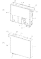
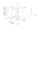
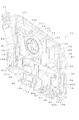
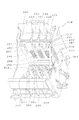
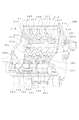
図1、図2は、それぞれ本発明のインクカートリッジ1の一実施例を、これを構成する容器本体8の表裏の構造を、また図3は底面から見た構造で示すものであって、略水平方向に延びる壁2により上下に分割され、下部領域に第1インク収容室3が形成され、また上部には後述する負圧発生機構となる差圧弁収容室4、及びフィルタを収容するフィルタ室5、及び第2、第3のインク収容室15、16が形成されている。
【0009】
これら差圧弁収容室4とフィルタ室5とは、厚み方向で壁6により分離され、差圧弁収容室側には凸部からなる弁座6a、及び貫通孔6bが形成されている。また、フィルタ室側にはフィルタ18を固定する枠部10が形成されている。
【0010】
上下の部屋は、一側部で上下方向に延びる壁11a、11b、及び水平方向に延びる壁11c、11dにより迷路状、より具体的には垂直面内で周回する流路を介して終端がフィルタ室5の上部領域の開口5aに連通されている。
【0011】
一方、貫通孔6bによりフィルタ室5と接続された差圧弁収容室4は、第1インク収容室3と隔離するように形成された流路13によりインク供給口14に連通されている。また、差圧弁収容室4、及びフィルタ室5を挟むように前述のインク収容室15、16が配置され、第1インク収容室3から上昇したインクに含まれている気泡をこれらインク収容室15、16にトラップするようになっている。
【0012】
容器本体8の上部には、容器本体8の外壁と若干の間隙を形成するように水平方向に延びる壁20を形成して流路21が設けられ、この流路21は、キャピラリ22を介して大気開放口17に連通されている。また流路21は、通気性膜24a、及び筒状部25を介して第1インク収容室3に連通されている。すなわち、第1インク収容室3は、筒状部25、通気性膜24a、キャピラリ22を介して大気開放口17に接続されている。
【0013】
キャピラリ22は、差圧弁収容室側の面に形成された蛇行溝を遮気性フィルム37により封止して形成されており、その一端22aが大気開放口17に接続され、他端が通気性膜24aと遮気性膜24bとにより区画された領域に溝23cを介して連通されている。通気性膜24aは、容器本体8に形成された凹部23の中段に張設されている。具体的には、凹部23の中段に膜支持部23aを形成してここに通気性膜24aを張設するとともに、凹部23の上面23bに遮気性膜24bを張設して外気と遮断されている。
【0014】
流路21は、筒状部25を介して第1インク収容室3に連通されている。筒状部25の上部には開口26が設けられ、弾性変形可能な遮気性膜27により封止され、また筒状部25には図示しない常閉型の弁が収容されている。
この構成により、インクカートリッジ1が記録装置に装着された際に進入してくる作動杆により膜27が弾性変形して弁が開弁され、その結果第1インク収容室3が流路21に連通する。
【0015】
インク供給口14が形成されている下面には、差圧弁収容室4の直下に下面側に開口する凹部30が形成され、ここにインクカートリッジ識別用の識別用突出部31が形成されている。またこの下面には製造時にインクを充填するためのインク注入口33、34も形成されている。
【0016】
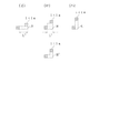
凹部30は、図4に示したように容器の長手方向Xを3つ、また容器の幅方向Yを2つ、さらに容器の高さ方向Zを6つに区分した領域を座標点とし、座標点を選択するようにして識別係合部を構成する複数の識別用突出部31−1、31−2、31−3、31−4が座標点(X1、Y2、Z1)、(X1、Y1、Z6)、(X3、Y2、Z3)、及び(X3、Y1、Y2、Z5)に配置されている。いうまでもなく、座標点を、それぞれのインクカートリッジの種類、例えばインクの種類等に対応して一義的に設定しておくことにより、インクの種類が異なるインクカートリッジを装着するといったミスを防止することができる。
【0017】
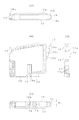
図5(イ)、(ロ)は、それぞれ負圧付与手段としての差圧弁の一実施例を、閉弁状態、及び開弁状態で示すものであって、外周に環状の厚肉部40aを、また中心に貫通孔40bが穿設された厚肉部40cを、さらに厚肉部近傍に略S字条の屈曲部40dを備えた膜弁40を、円筒状のホルダ41に固定して差圧弁収容室4に嵌装されている。中心の厚肉部40cと容器本体72の間にはコイルバネ42が挿入されている。コイルバネ42は、記録ヘッドでのインクの消費によりインク供給口14に一定の負圧が作用した時点で膜弁40を弁座6aから離れさせ(図5(ロ))、また記録ヘッドにインクの供給が終了した時点で膜弁40を弁座6aに弾接させる(図5(イ))ことができるようにその弾圧力を調整されている。
【0018】
このように構成された容器本体8は、フィルタ室側の面を蓋体36により、また差圧弁室側の面に遮気性フィルム37を張設して封止されて密封容器に構成され、インク供給口14をインク供給針の挿入により破砕可能なフィルムにより封止した状態で、底面のインク注入口33、34にインク注入手段を接続してインクを充填し、充填後、これらのインク注入口33、34を栓体、または遮気性フィルムで封止してインクカートリッジ1に仕上げられる。
【0019】
図6(イ)は、上述したインクカートリッジ1に適したインクカートリッジホルダ50の一実施例を示すものであって、基部51にインクカートリッジの前面、及び前面に隣接する両側面に一致する壁52、53、54と、インクカートリッジの垂直凹部に対向する位置に凸部55を設けて構成され、インクカートリッジ種類を検出するための識別片56が、インクカートリッジの挿抜方向に伸びるように形成されている。
【0020】
この識別片56は、具体的には複数の片56−1、56−2、56−3から構成されていて、それぞれがキャリッジの表面からインクカートリッジの凹部30に形成された識別用突出部31−1、31−2、31−3、31−4の下面に到達する長さ、つまり適合するインクカートリッジを受容に際しては、識別係合部である識別用突出部31−1、31−2、31−3、31−4に衝突しないサイズに選択されている。
これにより、このキャリッジに適したインクカートリッジが装着された場合には、ホルダ50への装着を可能とし、また不適合なインクカートリッジが装着されようとした場合には、インク供給針へのさらなる移動をキャリッジの識別片と協同して阻止する。
【0021】
この実施例において、インクカートリッジ1をインクカートリッジホルダ50に装着すると、前面側の3面が壁52、53、54に、また凹部が凸部55にガイドされて図6(ロ)に示したように所定位置に位置決めされ、また弁体27が図示しない記録装置の作動杆により押圧され開弁する。これにより、第1インク収容室3がキャピラリ、流路21を介して大気に開放される。
【0022】
この状態で、記録ヘッドでインクが消費されてインク供給口14に負圧が作用すると、膜弁40が差圧を受けてコイルバネ42の付勢力に抗して弁座6aから離れる。第1インク収容室3のインクはフィルタ18を通過して貫通孔6bから差圧弁収容室4に流れ込み、膜弁40の貫通孔40bを通過して流路13を経由してインク供給口14に流れ込む。
【0023】
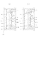
他方、インク供給口14からのインクの流れ出しによりフィルタ室5に負圧が作用すると、図7に示したように第1インク収容室3のインクは壁11により区画された垂直方向に伸びる流路A、最上部で水平方向に伸びる流路B、フィルタ室5を区画する壁と水平方向に伸びる壁2とで形成された流路C、垂直な流路D、水平な流路Eを経由して第1インク収容室3のインクがフィルタ室5の上部に吸い込まれる。このように第1インク収容室3のインクは、2つのインク収容室15、16を経由し、その底部から流れ出すため、インクの気泡は、インク収容室15、16の上部に停滞させられてフィルタ室5に流入する以前に可能な限り除去される。
【0024】
このようにしてインクが消費されると、下部に位置する第1インク収容室3のインクが上部のフィルタ室5に吸い上げられ、その後、差圧弁機構を介してインク供給口14に供給される。
【0025】
他方、インクカートリッジ1のインクが消費されたり、また途中でインク種を変更するべくインクカートリッジ1が取り外されると、第1インク室3と流路21とを連通していた筒状部25内の弁体が記録装置側の作動杆の支持を失って閉弁し、また膜弁40もバネ42により付勢されて弁座6aに弾接しているため、インク供給口14からのインクの漏れ出しが防止される。
【0026】
なお、上述の実施例においては、識別用の突起をインクカートリッジに一体に形成しているが、図8に示したようにインクカートリッジ1を構成する容器本体8に凹部60を形成し、この凹部60の内周に挿入固定可能な枠体61を別体として構成するとともに、この枠体61の内面に識別用突出部31を形成して識別用ブロック62を構成する。
この実施例によれば、インクカートリッジ1の種類に対応して識別用突出部31の位置を異ならせた識別用ブロック62を用意することで、容器本体8を各種のインクの容器として共通に使用することができる。
【0027】
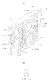
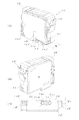
図9(イ)、(ロ)、及び図10(イ)乃至(ニ)は、それぞれ本発明のインクカートリッジの一実施例の外観を示すものであって、インクカートリッジ71は、一方の面が開口した扁平な矩形状の有底箱型の容器本体72と、この開口を封止する蓋体73とを主体として構成されている。キャリッジへの挿入方向の先端側、この実施例では底面の、長手方向の一方に偏するようにインク供給口74が、上部の側方にはそれぞれ係止部材75、76が形成されている。
【0028】
またインク供給口側の係止部材75の下部の凹部72bには記憶手段77が設けられ、他方の係止部材76の下部にはバルブ収容室78が形成されている。インク供給口74の近傍で、かつ容器本体72の中央領域にはインクカートリッジ71の挿抜方向に延びるスリット部79が形成されている。
【0029】
一方、インクカートリッジ71が装着されるキャリッジ200は、図11に示したように底面に記録ヘッド201を設けるとともに、記録ヘッド201に連通するインク供給針202を設けて構成されている。インク供給針202が設けられている領域から離れた領域にはカートリッジ押圧部材、この実施例では板バネ203が設けられ、またインク供給針202と板バネ203との間に位置決め用の凸片204がインクカートリッジ71の挿抜方向に延出形成されている。
インク供給針202の側の側壁205には電極206が配置され、その上部に係止部材75の突起75aと係合する凹部207が形成され、対向する側の側壁208には、インクカートリッジ71の係止部材76の突起76aと係合する凹部209が形成されている。
【0030】
このような構造を採ることにより、図12(イ)に示したようにインク供給口74を奥側として挿入し、板バネ203に抗して押え込むと、スリット部79が凸片204に規制されるため、一方に偏して設けられた板バネ203によりインク供給口74の側が下方となるように回転力(図中、矢印A)を受けるとしても、姿勢が規定の挿抜方向、この実施例では上下方向に平行となるように規制される。
【0031】
さらにインクカートリッジ71を板バネ203に抗して押し込むと、図12(ロ)に示したように係止部材75の突起75aが、係止部材75の全体の弾性に抗して凹部207に落ち込んで係合し、また、係止部材76が凹部209にも係合する。
【0032】
一方、交換等によりインクカートリッジ71をキャリッジ200から取り外す場合には、係止部材75を容器本体72側に弾圧すると、係止部材75の突起75aが凹部207から離れるから、この状態で引き抜くと、インク供給針202に曲げ力などを作用させることなく取り外すことができる。
【0033】
図13、図14は、同上インクカートリッジ71を構成する容器本体72に形成された流路の一実施例を示すものであって、容器本体72は、略水平方向、より詳細にはインク供給口74の側が若干下方となるように延びる壁80により上下に分割されている。
下部領域には第1インク収容室81が、また上部は、壁80を底面とするように容器本体72の壁82と一定の間隙を持たせて大気連通路83を形成するように枠部84により区画されている。枠部84は、底部に連通口85aが形成された垂直な壁85により分割され、一方の領域を第2インク収容室86として、また他方の領域を第3インク収容室87として形成されている。
【0034】
第2インク収容室86と容器本体72の底面72aとは、下端が第1インク収容室81と連通し、また上端が第2インク収容室86の底部に連通する吸い上げ流路88により接続されている。
【0035】
吸い上げ流路88の下部に連通口89a、89bを備えた壁89が形成されている。またこの吸い上げ流路88に対向する箇所には容器本体72に外部からインクを注入するための開口90と、インク注入時に第1インク収容室81と連通して排気を行う開口91とが形成されている。
【0036】
第3インク収容室87は、枠部84の上面84aと一定の間隙を隔てて壁92と、壁94、96、85とにより、また第4インク収容室93は、壁94、96、97により区画されている。壁92に連続してフィルタ125を収容する壁94により区画され、さらにフィルタ室と対向する他方の面に差圧弁収容室103(図15)を、壁95により区画されている。壁95にはフィルタ125を通過したインクをフィルタ室104と背腹関係に形成された差圧弁収容室103に導く貫通穴95aが設けられている。
【0037】
壁94の下部には壁80との間に連通口96aを備えた区画壁96が、また枠部84との間には下部に連通口97aを備えた区画壁97を設けてインク流路98が形成されている。インク流路98の上部は、貫通穴99を介してインクカートリッジ71の表面側に連通している。
【0038】
この貫通穴99は、図14に示したように壁97に連続するように形成された壁100により分離され、図15に示したようにその凹部100aを介してフィルタ室104の上部に連通されている。より詳細には、貫通穴99は凹部100aを介して壁100、94、92により区画された領域101に連通し、フィルタ室104を区画する壁94の上部の連通口94aを介してフィルタ室104の上部に連通している。
【0039】
差圧弁収容室103の下部とインク供給口74とは、図15(イ)に示したように表面に形成された凹部105と、この凹部105を覆う遮気性フィルムとからなる流路により接続されている。なお、図中符号105aは、インク供給口側に入り込んだ深部を示す。
【0040】
また、容器本体72の表面には、可及的に流路抵抗が高くなるように蛇行する細溝106と、これの周囲に幅広の溝107と、第2インク収容室86に対向する領域に矩形状の凹部108が形成されている。矩形状の凹部108にはさらに一段下がった位置に枠部109とリブ110が形成され、これらに撥インク性と通気性とを備えた通気性フィルムを張設して大気通気室が区画形成されている。凹部108の底面には貫通穴111が形成され、第2インク収容室86の壁112で区画された細長い領域113(図13)に連通されている。また凹部108の、通気性フィルムよりも表面側の領域で細溝106が連通されている。領域113の他端は貫通穴114、連通用の溝115、及び貫通穴116(図15(ロ))を介してバルブ収容室78に連通されている。
【0041】
バルブ収容室78の、インクカートリッジの挿入側の先端、この実施例では図14に示したように下部に窓78aが形成されて開放されていて、記録装置本体のキャリッジ200に設けられた複数の識別片210、211、212(図11)、及びバルブ作動杆が進入可能な後述する識別用ブロック140が装着されている。
【0042】
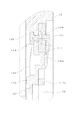
図16は、前述の差圧弁収容室103近傍の断面構造を示すものであって、差圧弁収容室103には、バネ120とエラストマー等の弾性変形可能な材料により構成され、中心に貫通穴121を備えた膜弁122が収容されている。膜弁122はその周囲を環状の厚肉部122aと、この厚肉部122aと一体的に形成された枠部124とを備え、この枠部124を介して容器本体72に固定され、またバネ120は、一端を膜弁122のバネ受け部122bに、他端を収容室の蓋体123のバネ受け部123aに支持されている。
【0043】
なお、図中符号125はフィルタ室104に設けられたフィルタを、また符号126、127は、容器本体72の表面、及び開口面側に貼付された遮気性フィルムをそれぞれ示す。フィルム126は、図14における枠部80、84、壁85、92、94、96、97、100、及び112に溶着等により接着され、上部に位置するインク収容室86、87、93を形成している。
【0044】
このような構成により、フィルタ125を通過したインクは、インク流通口95aを通過して膜弁122に阻止される。この状態でインク供給口74の圧力が低下すると、膜弁122がバネ120の付勢力に抗して弁座部95bから離れるため、貫通穴121を通過し、凹部105により形成された流路を経由してインク供給口74に流れ込む。
【0045】
インク供給口74のインク圧力が所定の値に上昇すると、膜弁122がバネ120の付勢力に負けて弁座部95bに弾接され、インクの流通が遮断される。このような動作を繰返すことにより一定の負圧を維持しながらインクをインク供給口74に排出することができる。
【0046】
図17は、大気連通用のバルブ収容室78の断面構造を示すものであって、バルブ収容室78を区画する壁には貫通穴130が穿設され、ここにゴム等の弾性部材により構成された押圧部材131がその周囲を容器本体72に支持されて移動可能に挿入されている。押圧部材131の進入側の先端には、下端を突起133により固定され、中央部を突起134により規制された板バネなどの弾性部材132に支持され、貫通穴130に常時付勢された弁体135が配置されている。
【0047】
また大気連通用のバルブ収容室78に隣接し、かつ弁体135の押圧部材131を変位させることができるように図18に示した識別用ブロック140が装着されている。識別用ブロック140は、爪140a、140bにより容器本体72の凹部150(図15)に固定される基体に、インクカートリッジ71の挿入方向に平行で、かつインクカートリッジ71の一定の幅をもった複数、この実施例では3本の溝141、142、143を形成し、また特定の1つの溝142には押圧部材131を変位させるアーム144が、一定の位置に一体に形成されている。
なお、アーム144が配置されている溝142の、識別片の進入側(図中、下方)には隣接する一方の溝、この実施例では溝141と一体となるように開口部がDと拡幅されている。これにより、インクカートリッジ71の装着時に、作動杆213の位置が若干変化していても広い開口部で捕まえて、溝142に進入させることができる。
【0048】
アーム144は、若干内側に位置するように回動支点144aにより回動可能で、かつ引き抜き側、この実施例では上部側が作動杆213(図21)の進入路に斜めに突出するように構成されている。また、それぞれの溝141乃至143には、キャリッジ200の識別片210、211、212の先端に対向するように識別用突出部141a、142a、143aが形成されている。
【0049】
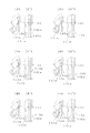
このような構成により、アーム144の位置を一定とする一方、これら突出部141a、142a、143aの位置を、図19(イ)(イ’)乃至(ヘ)(ヘ’)に示したように溝141、142、143内で変更し、また対応して識別片210、211、212の先端の位置を、装着可能なインクカートリッジ71の突出部141a、142a、143aに対応させて設定するすることにより、不適合なインクが収容されたインクカートリッジ71が装着されるのを防止することができる。
【0050】
これら突出部141a、142a、143aの位置は、インクカートリッジ71の挿抜方向だけではなく、インクカートリッジ71の厚み方向の位置をも変えることができるため、突出部141a、142a、143aを3次元的に配列することができ、識別領域形成面積の拡大を招くことなく多くのインク種を識別することができる。また、各溝141、142、143の奥行き(容器本体2の厚み方向)を、各溝ごとに前述の識別片210、211、212を複数挿通できるサイズに設定すると、更に多くの種類を識別することが可能となる。
【0051】
図20、図21は、インクカートリッジが装着されるキャリッジの一実施例を示すものであって、複数個、この実施例ではブラックインク用インクカートリッジを1つと、カラーインク用インクカートリッジを3つが装着可能に構成されている。
すなわち、一側側に若干幅広の第1の装着領域220を設け、これに隣り合うように同一幅の第2乃至第4の装着領域221乃至223が、両端のリブ224〜226、リブ227〜229により区画されている。
【0052】
各インクカートリッジの装着領域には、図11に基づいて前述したように、記録ヘッド201に連通するインク供給針202が設けられ、インク供給針202が設けられている領域から離れた領域には押圧部材、この実施例では板バネ203が設けられ、またインク供給針202との間に位置決め用の凸片204がインクカートリッジの挿抜方向に延出形成されている。
【0053】
また、インク供給針202の側の側壁205には電極206が配置され、その上部には係止部材75の突起75aと係合する凹部207が形成されている。
【0054】
この実施例では、位置決め用の凸片204は、図22(イ)に示したようにインクカートリッジ71の表面に平行に延びる側部204aが形成され、位置決めの確実性と、薄くて長い凸片204の強度を確保するように構成されている。これに対応するようにインクカートリッジ71のスリット部79は、インクカートリッジ71の挿入方向の先端が、図22(ロ)に示したように少なくとも側部204aに対向する領域に凹部79aが形成されていて表面側に延出されている。
【0055】
インク供給針202の周囲には、インクカートリッジ71のインク供給口74を挟むように形成された断面「コ」の字状のリブ74a、74aと係合するリブ202aが形成されていて、これらリブによりインク供給口74にインク供給針202が挿通された状態に保持することができる。
【0056】
このように構成されたキャリッジ200にインクカートリッジ71を装着すると、キャリッジ200の識別片210、211、212が識別用ブロック140の溝141、142、143に進入し、また作動杆213が溝142に進入する。インクカートリッジ72が、この装着領域に適合する場合には、インクカートリッジ71のインク供給口74がインク供給針202に係合可能な位置まで移動し、この過程で作動杆213が識別用ブロック140のアーム144を押圧して大気連通用のバルブ収容室78の弁体135を開弁させる。これにより、インクカートリッジ71の第1のインク収容室81を大気に連通させ、前述したごとく記録ヘッドにインクを供給することが可能となる。
【0057】
一方、装着領域に適合しないインクカートリッジが装填されると、インクカートリッジ71のインク供給口74がインク供給針202に係合する以前に、識別用ブロック140の溝141、142、143の識別用突出部141a、142a、143aのいずれかがキャリッジ200の識別片210、211、212に衝突して移動を阻止される。これにより、インク供給口74がインク供給針202と係合する以前で、かつ作動杆213が識別用ブロック140のアーム144を押圧する以前に装着ミスに気付くことができる。
【0058】
上述した識別用ブロックの機能について詳述する。
例えば図19に示した識別用ブロック140のように3つの識別片挿入領域、つまり溝141、142、143が準備され、かつ各挿入領域の識別可能領域数、つまり座標数が図18(ハ)に示したように3つの場合には、表1に示したように27通りの異なったパターンを設定することができる。
【表1】

【0059】
一方、識別片挿入領域の1つ、上述の実施例では溝142の、最先端側に大気開放弁の押圧部材131を変位させるアーム144を配置する関係上、この溝142に設定できる座標が2つとなり、このため表2に示したように18通りだけのパターンが設定できる。
【表2】
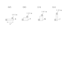
上述の識別用ブロック140に対応する識別片210、211、213は、図23に示したように相対高さHが1で、かつ溝の奥側の相対長さLが3(パターンA)、相対高さHが2で、かつ溝の奥側の相対長さLが2(パターンB)、または相対高さHが2で、かつ溝の下側の奥側の相対長さL1が2で、かつ溝の上側の奥側の相対長さL2が1(パターンB’)、及び相対高さHが3で、かつ溝の奥側の相対長さLが1(パターンC)との配置位置、つまり溝141、142、143のいずれに対応させるかにより、18通りのカートリッジを識別することができる。
なお、識別片のパターンが図23(ニ)乃至(ヘ)に示した形状の場合には、パターンA乃至Cよりも小さいため、これらパターンA乃至Cを識別する溝にも進入可能となり、不適合なインクカートリッジを確実には排除することができないが、パターンの組み合わせ次第では使用可能となる。
【0061】
そして、前述の識別片A乃至Cに対応させて識別用ブロックの各溝141、142、143の奥ゆきを、パターンAに対しては相対長さL’を3とし、またパターンB、及びB’のものに対しては2とし、さらにパターンCに対しては相対長さL’を1とするように図中クロスハッチングで示す座標点をも規制することにより、これら3種類のパターンA乃至Cを確実に識別して、インクカートリッジ71の誤挿入を防止することができる(なお、パターンBに対応する識別用ブロックの溝と完全に符合する形ではパターンB’が一致しないものの挿入可能であるから、パターンBとパターンB’とはいずれか一方だけ他のパターンA、Cと組み合わせて使用可能である)。
【0062】
同様に識別用ブロック140に4つの溝を形成した場合には、各溝141、142、143の奥行きを相対長さを4、また各溝のインクカートリッジの挿抜方向の相対高さ4として、図25(イ)乃至(ニ)に示したように相対高さHが1で、相対長さLが4(パターンE)、相対高さHが2で、相対長さLが3(パターンF〜F”)、相対高さHが3で、相対長さLが2(パターンG〜G”)、及び相対高さHが4で、相対長さLが1(パターンJ)の識別片を用意する。
【0063】
これにより前述したように相対高さが最も高い識別片J以外は、図26(イ)乃至(ニ)に示したように、溝の奥行き、つまり相対長さL”を図中クロスはハッチングで示した領域を規制することにより、確実に識別することができる。
【0064】
すなわち、インクカートリッジの挿入方向に平行な方向、及びインクカートリッジの奥行き方向にそれぞれN(Nは3以上の整数)の座標点を有する場合には、第1パターンの識別片は、インクカートリッジの挿入方向に平行な軸方向第1の座標点、及びインクカートリッジの奥行きに平行な軸方向第nの座標点に到達する端部を備え、2≦i≦(n−1)なる整数iについて、第iパターンの識別片が、インクカートリッジの挿入方向に平行な軸方向第iの座標点と、インクカートリッジの奥行き方向に平行な軸方向第(n−i+1)の座標点に到達する位置とに端部を備え、また第nパターンの識別片は、インクカートリッジの挿入方向に平行な軸方向第n座標点と、インクカートリッジの奥行き方向に平行な軸方向第1の座標点に到達するように端部を形成すればよい。
【0065】
ところで、幅広とされた装着領域220に装填されるインクカートリッジ71’は、基本的には図10乃至図17に示した第2、及び第4の装着領域に装填されるインクカートリッジ71と同様の構造に構成されるものではあるが、図27に示したように容器本体72’は、開口面の形状は同一で、その深さWだけ大きくなるように構成されている。これにより、容器本体72’の深さWを変更するだけで収容可能なインク量を増加することができる。
【0066】
そして、インク供給口74’、記憶手段77’は、その配列中心が、他のインクカートリッジと同様に容器本体72’の表面、つまり底から一定の位置W1となるように設定されている。なお、識別用ブロック140’は、容器本体72’の表面側に装着されているから、当然に同一の位置に配置されることになる。
【0067】
また、係止部材75’、76’は、装填時にインク供給口74’に確実に押圧力が作用するように、図28(イ)に示したようにインク供給口74’と同様に容器本体72’の側に偏して配置されている。
また、容器本体2に貼付される装飾用フィルム130(図16(イ))のインク注入口90、91’に対向する領域に舌部230aを形成し、図28(ロ)に示したように舌部230aをインク注入口90’、91’を封止してもよい。
【0068】
なお、上述の実施例においては、識別用突出部が識別用ブロックに一体に形成されているが、識別用ブロックに孔を設け、ここにピンを挿入するようにしてもよい。
【0069】
また、上述の実施例においては識別用ブロックに複数の溝を形成し、この溝に識別用突出部を形成しているが、図29に示したように識別片A、B、Cの外形形状に一致する凹部を備えたブロック220として形成しても同様の作用を奏することは明らかである。この場合には、弁体135を開弁させる作動杆213が進入できる間隙をインクカートリッジ71との間に形成したり、またブロック自体に凹部、貫通孔を形成しておくことにより、弁体の近傍にブロックを配置することができる。
【0070】
また、識別ブロックを弁体の開閉に近接させて配置する必要がない場合には、インクカートリッジを構成する容器に凸片からなる識別片を設け、キャリッジの対応する箇所に前述の識別ブロックを装着、固定するようにしてもよい。
また、識別片及び識別ブロックと、インクカートリッジの記憶手段を組み合わせ、装着ミスが生じないインクカートリッジ同士では、記憶手段に格納されている情報におり適否を判定することができる。
さらに、識別用係合部は、識別片と当接する必要はなく、他の識別片と区別できる程度にクリアランスが設定されていてもよい。
【0071】
さらに、上述の実施例においては、負圧発生手段として差圧弁を使用する場合について説明したが、スポンジ等の多孔質材にインクを含浸させ、細孔の毛細管力により負圧を維持するようにしても同様の作用を奏することは明らかである。
【0072】
【発明の効果】
以上説明したように本発明によれば、空間を三次元に利用して識別用規制部を配置するため、組み合わせ数が多くなり、記録装置に適した多種類のインクカートリッジをミスなく装着できる。
【図面の簡単な説明】
【図1】図(イ)、(ロ)は、それぞれ本発明のインクカートリッジの一実施例の表裏の構造を示す図である。
【図2】図(イ)、(ロ)は、それぞれ同上インクカートリッジを封止している側面形成部材を取り外して示す図である。
【図3】同上インクカートリッジの底面の構造を示す図である。
【図4】同上インクカートリッジに形成された誤挿入防止形成領域を拡大して示す説明図である。
【図5】図(イ)、(ロ)は、それぞれ負圧発生機構を構成する差圧弁の一実施例を、閉弁状態、及び開弁状態で示す断面図である。
【図6】図(イ)、(ロ)は、それぞれ同上インクカートリッジに適したインクカートリッジホルダを一部を切り欠いて示す図、及びインクカートリッジが装着された状態を示す図である。
【図7】インクカートリッジに形成されているフィルタ室側のインク流路を中心に示す正面図である。
【図8】本発明の他の実施例を示す図である。
【図9】図(イ)、(ロ)は、それぞれ本発明のインクカートリッジの一実施例の表裏の外観を示す図である。
【図10】図(イ)乃至(ニ)は、それぞれ同上インクカートリッジの上面図、正面図、底面図、及び側面図である。
【図11】同上インクカートリッジが装着されるキャリッジの一実施例を示す断面図である。
【図12】図(イ)、(ロ)は、それぞれインクカートリッジをキャリッジに装着する過程を示す図である。
【図13】同上インクカートリッジを構成する容器本体の底面の構造を示す斜視図である。
【図14】同上インクカートリッジを構成する容器本体の開口面の構造を示す斜視図である。
【図15】図(イ)は同上インクカートリッジを構成する容器本体の表面の構造を示す斜視図であり、また図(ロ)は、連通用の溝に形成された貫通孔を示す図である。
【図16】負圧発生手段収容室の断面構造を拡大して示す図である。
【図17】大気連通用のバルブ収容室の断面構造を拡大して示す図である。
【図18】図(イ)、(ロ)は、それぞれ識別用ブロックの一実施例を示す斜視図と正面図であり、また図(ハ)は、識別用ブロックに設定されている座標点を示す図である。
【図19】図(イ)(イ’)乃至(ヘ)(ヘ’)は、それぞれ識別用ブロックによる識別可能な凸部の形態を示す斜視図と正面図である。
【図20】複数のインクカートリッジが収容可能に構成されたキャリッジの一実施例を示す斜視図である。
【図21】同上キャリッジの向きを変えて示す斜視図である。
【図22】図(イ)、(ロ)は、それぞれ同上キャリッジのインク供給針の近傍、及びインクカートリッジのインク供給口の近傍を拡大して示す図である。
【図23】図(イ)乃至(ハ)、及び図(ニ)乃至(ヘ)は、それぞれ識別片として適した形状、及び不適合な形状を示す図である。
【図24】図(イ)乃至(ハ)は、同上識別片を識別用ブロックで識別のために識別用ブロックに形成すべき規制部を示す図である。
【図25】図(イ)乃至(ニ)は、それぞれ識別片の他の実施例を示す図である。
【図26】図(イ)乃至(ニ)は、同上識別片を識別用ブロックで識別のために識別用ブロックに形成すべき規制部を示す図である。
【図27】図(イ)乃至(ハ)は、それぞれ同上インクカートリッジの他の実施例を示す斜視図と底面図である。
【図28】図(イ)、(ロ)は、それぞれ同上インクカートリッジのインク注入口の封止構造を示す図である。
【図29】識別用ブロックの他の実施例を示す斜視図である。
【符号の説明】
1 インクカートリッジ
8 容器本体
14 インク供給口
15、16 インク収容室
31 識別用突出部
31−1〜31−4 識別用突出部
50 インクカートリッジホルダ
56−1〜56−3 識別片
61 枠体
62 識別用ブロック
71 インクカートリッジ
72 容器本体
77 記憶手段
78 バルブ収容室
140 識別用ブロック
141〜143 溝
141a〜143a 識別用突出部
144 アーム
202 インク供給針
206 電極
210〜212 識別片
213 作動杆[0001]
TECHNICAL FIELD OF THE INVENTION
The present invention relates to a technique for identifying an ink cartridge that supplies ink at an appropriate negative pressure to a recording head that ejects ink droplets in response to a print signal.
[0002]
[Prior art]
Ink jet recording apparatuses are usually equipped with an ink jet recording head that ejects ink droplets in response to a print signal on a carriage that reciprocates in the paper width direction of recording paper, and supplies ink from an external ink tank to the recording head. Is configured. Such an ink storage container such as an ink tank is removably mounted on a carriage in a small recording apparatus, and is installed in a box in a large recording apparatus, and is mounted on a box via an ink supply tube. Connected to the recording head.
[0003]
The ink tank mounted on the carriage usually contains a porous material such as a sponge and impregnates the ink with the ink, in order to minimize the pressure change due to the ripple of the ink due to the reciprocation of the carriage. Have been.
[0004]
In addition, even when ink is supplied from a large-capacity ink bag installed in a box via an ink supply tube, a change in ink pressure due to bending of the tube due to reciprocation of the carriage is prevented. The ink is supplied to the recording head via a sub-tank having a damping function for preventing a change in ink pressure due to the movement of the recording head.
For this reason, in the former case, there is a problem that the size and weight of the ink tank are larger than the amount of ink that can be stored, and the shaking is in the latter case. There is a need for a mechanism for preventing a change in the pressure of the ink due to movement, and there is a problem that the structure is complicated.
Further, recording heads and inks have been improved with the aim of improving print quality, and inks suitable for recording heads have been specified by manufacturers.
On the other hand, since the ink cartridge is configured as a rectangular parallelepiped container in view of the structure of the recording apparatus, there is a problem that it is not easy to identify an ink cartridge suitable for the recording apparatus and a selection error occurs.
In order to solve such a problem, a convex portion is formed in the ink cartridge holder of the recording apparatus, and a concave portion is formed in the ink cartridge so as to engage with the convex portion, and the ink is formed only when the convex portion engages with the concave portion. The supply needle is configured to penetrate the ink supply port.
[0005]
[Problems to be solved by the invention]
However, if the weight of the ink cartridge is reduced to achieve high-speed printing, that is, if the capacity of the ink cartridge is reduced, there is a problem that the number of types of concave portions that can be formed in the narrow bottom portion is limited.
The present invention has been made in view of such a problem, an object thereof is to use an ink jet recording apparatus that can increase the number of types of suitability determination using a relatively narrow space, And an ink cartridge suitable for this.
[0006]
[Means for Solving the Problems]
In order to solve such a problem, the inkjet recording apparatus of the present invention isAn ink cartridge having an ink supply port and accommodating ink therein, and a plurality of identification piece insertion areas respectively corresponding to a plurality of identification pieces formed in a cartridge mounting area of the recording apparatus; In the area, the identification piece having a shape other than a predetermined shape is prevented from entering at a predetermined position in a first direction parallel to the insertion direction of the ink cartridge and in a second direction perpendicular to the first direction. Each of the identification engaging portions is formed, and the plurality of identification piece insertion regions are arranged so as to be arranged in a third direction perpendicular to the first direction and the second direction.
[0007]
[Action]
Since the identification pieces are arranged using the space in three dimensions, the number of combinations increases.
[0008]
BEST MODE FOR CARRYING OUT THE INVENTION
Therefore, the details of the present invention will be described below based on the illustrated embodiment.
FIGS. 1 and 2 show an embodiment of the
[0009]
The differential pressure
[0010]
The upper and lower chambers are maze-shaped by walls 11a and 11b extending on one side and
[0011]
On the other hand, the differential pressure
[0012]
At the upper part of the
[0013]
The
[0014]
The
With this configuration, when the
[0015]
On the lower surface where the
[0016]
As shown in FIG. 4, the
[0017]
FIGS. 5 (a) and 5 (b) show an embodiment of a differential pressure valve as a negative pressure applying means in a valve closed state and a valve open state, respectively. Further, a thick portion 40c having a through
[0018]
The container
[0019]
FIG. 6A shows an embodiment of an
[0020]
Specifically, the
Accordingly, when an ink cartridge suitable for this carriage is mounted, mounting to the
[0021]
In this embodiment, when the
[0022]
In this state, when ink is consumed by the recording head and a negative pressure acts on the
[0023]
On the other hand, when a negative pressure acts on the
[0024]
When the ink is consumed in this manner, the ink in the lower first
[0025]
On the other hand, when the ink in the
[0026]
In the above embodiment, the protrusion for identification is formed integrally with the ink cartridge. However, as shown in FIG. 8, a
According to this embodiment, the container
[0027]
FIGS. 9A, 9B, and 10A to 10D show the appearance of an embodiment of the ink cartridge according to the present invention. It is mainly composed of a flat rectangular bottomed box-shaped
[0028]
Further, a storage means 77 is provided in the
[0029]
On the other hand, the
An
[0030]
By adopting such a structure, as shown in FIG. 12A, when the
[0031]
When the
[0032]
On the other hand, when the
[0033]
13 and 14 show an embodiment of a flow path formed in the container
A first
[0034]
The second
[0035]
A
[0036]
The
[0037]
A
[0038]
The through
[0039]
As shown in FIG. 15A, the lower part of the differential pressure
[0040]
Further, on the surface of the
[0041]
A plurality of windows 78a formed in the
[0042]
FIG. 16 shows a cross-sectional structure in the vicinity of the above-described differential pressure
[0043]
In the drawing,
[0044]
With such a configuration, the ink that has passed through the
[0045]
When the ink pressure at the
[0046]
FIG. 17 shows a cross-sectional structure of a
[0047]
Further, an
Note that the
[0048]
The
[0049]
With such a configuration, while the position of the
[0050]
The positions of the protrusions 141a, 142a, and 143a can be changed not only in the insertion / removal direction of the
[0051]
FIGS. 20 and 21 show an embodiment of a carriage on which ink cartridges are mounted. A plurality of ink cartridges are mounted. In this embodiment, one black ink cartridge and three color ink cartridges are mounted. It is configured to be possible.
That is, the first mounting
[0052]
As described above with reference to FIG. 11, the ink supply needles 202 communicating with the
[0053]
An
[0054]
In this embodiment, as shown in FIG. 22A, the
[0055]
Around the
[0056]
When the
[0057]
On the other hand, when an ink cartridge that does not fit in the mounting area is loaded, before the
[0058]
The function of the above-described identification block will be described in detail.
For example, as shown in the
[Table 1]
[0059]
On the other hand, since the
[Table 2]
As shown in FIG. 23, the
In the case where the pattern of the identification piece has the shape shown in FIGS. 23D to 23F, since it is smaller than the patterns A to C, it is possible to enter the groove for identifying these patterns A to C, and Although a proper ink cartridge cannot be reliably eliminated, it can be used depending on the combination of patterns.
[0061]
The depth of each of the
[0062]
Similarly, when four grooves are formed in the
[0063]
As a result, as shown in FIGS. 26A to 26D, the depth of the groove, that is, the relative length L ″, except for the identification piece J having the highest relative height as described above, is cross-hatched in the figure. By regulating the indicated area, it is possible to identify the area reliably.
[0064]
That is, when there are N (N is an integer of 3 or more) coordinate points in a direction parallel to the insertion direction of the ink cartridge and in the depth direction of the ink cartridge, the identification piece of the first pattern is An end reaching an axial first n-th coordinate point parallel to the direction of the ink cartridge and an axial n-th coordinate point parallel to the depth of the ink cartridge, and an integer i satisfying 2 ≦ i ≦ (n−1). The i-pattern identification piece ends at an i-th coordinate point in the axial direction parallel to the insertion direction of the ink cartridge and at a position where it reaches the (n-i + 1) th coordinate point in the axial direction parallel to the depth direction of the ink cartridge. And the identification piece of the n-th pattern reaches the n-th coordinate point in the axial direction parallel to the insertion direction of the ink cartridge and the first coordinate point in the axial direction parallel to the depth direction of the ink cartridge. It may be formed end to so that.
[0065]
Incidentally, the ink cartridge 71 'to be loaded in the
[0066]
The ink supply port 74 'and the storage means 77' are arranged such that the arrangement center thereof is at a fixed position W1 from the surface of the container body 72 ', that is, the bottom, similarly to other ink cartridges. Since the identification block 140 'is mounted on the front side of the container body 72', it is naturally arranged at the same position.
[0067]
Further, the locking members 75 'and 76' are provided in the same manner as the ink supply port 74 'as shown in FIG. 28A so that the pressing force acts on the ink supply port 74' during loading. 72 '.
Further, a tongue 230a is formed in a region facing the
[0068]
In the above embodiment, the identification protrusion is formed integrally with the identification block. However, a hole may be provided in the identification block, and a pin may be inserted here.
[0069]
In the above-described embodiment, a plurality of grooves are formed in the identification block, and the identification protrusions are formed in the grooves. However, as shown in FIG. 29, the outer shapes of the identification pieces A, B, and C are formed as shown in FIG. Obviously, the same effect can be obtained even if the
[0070]
When it is not necessary to dispose the identification block close to the opening and closing of the valve element, an identification piece made of a convex piece is provided on the container constituting the ink cartridge, and the above-described identification block is attached to a corresponding portion of the carriage. , May be fixed.
In addition, the identification pieces and the identification blocks are combined with the storage unit of the ink cartridge, and the ink cartridges in which mounting errors do not occur can be determined based on the information stored in the storage unit.
Furthermore, the identification engaging portion does not need to contact the identification piece, and the clearance may be set to such an extent that it can be distinguished from other identification pieces.
[0071]
Further, in the above-described embodiment, the case where the differential pressure valve is used as the negative pressure generating means has been described. However, a porous material such as a sponge is impregnated with ink so that the negative pressure is maintained by the capillary force of the pores. It is clear that the same effect is obtained even when the above-mentioned operation is performed.
[0072]
【The invention's effect】
As described above, according to the present invention, since the discriminating regulating portions are arranged using the space three-dimensionally, the number of combinations increases, and various types of ink cartridges suitable for the recording apparatus can be mounted without mistake.
[Brief description of the drawings]
FIGS. 1A and 1B are diagrams showing the front and back structures of an embodiment of an ink cartridge according to the present invention, respectively.
FIGS. 2 (a) and 2 (b) are views showing a state where a side surface forming member sealing the ink cartridge is removed.
FIG. 3 is a diagram showing a structure of a bottom surface of the ink cartridge.
FIG. 4 is an enlarged view showing an erroneous insertion prevention forming area formed in the ink cartridge;
FIGS. 5A and 5B are cross-sectional views showing one embodiment of a differential pressure valve constituting a negative pressure generating mechanism in a closed state and an open state, respectively.
FIGS. 6 (a) and 6 (b) are a view showing an ink cartridge holder suitable for the same ink cartridge, respectively, with a part cut away, and a view showing a state where the ink cartridge is mounted.
FIG. 7 is a front view mainly showing an ink flow path on the filter chamber side formed in the ink cartridge.
FIG. 8 is a diagram showing another embodiment of the present invention.
FIGS. 9A and 9B are front and back views of an embodiment of an ink cartridge according to the present invention, respectively.
FIGS. 10A to 10D are a top view, a front view, a bottom view, and a side view of the same ink cartridge, respectively.
FIG. 11 is a sectional view showing an embodiment of a carriage on which the ink cartridge is mounted.
FIGS. 12A and 12B are diagrams illustrating a process of mounting an ink cartridge on a carriage, respectively.
FIG. 13 is a perspective view showing a structure of a bottom surface of a container main body constituting the ink cartridge.
FIG. 14 is a perspective view showing a structure of an opening surface of a container main body constituting the ink cartridge.
FIG. 15A is a perspective view showing the structure of the surface of a container main body constituting the ink cartridge, and FIG. 15B is a view showing a through hole formed in a communication groove. .
FIG. 16 is an enlarged view showing a cross-sectional structure of a negative pressure generating means housing chamber.
FIG. 17 is an enlarged view showing a cross-sectional structure of a valve accommodating chamber for communicating with the atmosphere.
18 (a) and (b) are a perspective view and a front view, respectively, showing an embodiment of an identification block, and FIG. 18 (c) shows coordinate points set in the identification block. FIG.
FIGS. 19A to 19F are a perspective view and a front view, respectively, showing a form of a convex portion that can be identified by an identification block.
FIG. 20 is a perspective view illustrating an embodiment of a carriage configured to be capable of accommodating a plurality of ink cartridges.
FIG. 21 is a perspective view showing the same carriage in a different direction.
FIGS. 22A and 22B are enlarged views of the vicinity of the ink supply needle of the carriage and the vicinity of the ink supply port of the ink cartridge, respectively.
FIGS. 23 (a) to 23 (c) and FIGS. 23 (d) to 23 (f) are diagrams respectively showing a shape suitable as an identification piece and an inappropriate shape.
FIGS. 24 (a) to (c) are diagrams showing a restriction portion to be formed on the identification block for identification by the identification piece in the identification block.
FIGS. 25A to 25D are diagrams showing another embodiment of the identification piece.
FIGS. 26 (a) to 26 (d) are diagrams showing a restriction portion to be formed on the identification block for identification by using the identification piece in the identification block.
FIGS. 27A to 27C are a perspective view and a bottom view, respectively, showing another embodiment of the same ink cartridge.
FIGS. 28A and 28B are diagrams showing a sealing structure of an ink injection port of the ink cartridge, respectively.
FIG. 29 is a perspective view showing another embodiment of the identification block.
[Explanation of symbols]
1 Ink cartridge
8 Container body
14 Ink supply port
15, 16 Ink storage chamber
31 Identification protrusion
31-1 to 31-4 Projection for identification
50 Ink cartridge holder
56-1 to 56-3 Identification Piece
61 Frame
62 Identification block
71 Ink cartridge
72 Container body
77 storage means
78 Valve accommodation room
140 Identification block
141-143 groove
141a-143a Projecting part for identification
144 arm
202 Ink supply needle
206 electrodes
210-212 Identification piece
213 Operating rod
Claims (9)
前記識別片挿入領域には、前記インクカートリッジの挿入方向に平行な第1の方向、及び前記第1の方向に垂直な第2の方向における所定の位置に、所定の形状以外の前記識別片の進入を阻止する識別係合部がそれぞれ形成されており、
前記複数の識別片挿入領域は、前記第1の方向及び前記第2の方向に垂直な第3の方向に並ぶように配設されていることを特徴とするインクカートリッジ。A container having an ink supply port and containing ink therein, and an ink cartridge having a plurality of identification piece insertion areas respectively corresponding to the plurality of identification pieces formed in the cartridge mounting area of the recording apparatus,
The identification piece insertion area has a first direction parallel to the direction in which the ink cartridge is inserted, and a predetermined position in a second direction perpendicular to the first direction. Identification engagement portions for preventing entry are formed respectively,
The ink cartridge according to claim 1, wherein the plurality of identification piece insertion areas are arranged in a third direction perpendicular to the first direction and the second direction.
前記第1の方向の長さが前記第2の方向の長さよりも長い第1の識別片の進入を許可する第1の識別片挿入領域と、
前記第1の方向の長さが前記第1の識別片よりも短く、前記第2の方向の長さが前記第1の識別片よりも長い第2の識別片の進入を許可する第2の識別片挿入領域と、
により形成されている請求項1に記載のインクカートリッジ。The identification piece insertion area,
A first identification piece insertion area that permits the entry of a first identification piece whose length in the first direction is longer than the length in the second direction;
A second length that allows a second identification piece whose length in the first direction is shorter than the first identification piece and whose length in the second direction is longer than the first identification piece to enter; An identification piece insertion area,
The ink cartridge according to claim 1, wherein the ink cartridge is formed by:
1)前記第1の方向の長さが前記第2の方向の長さよりも長い第1の識別片、
2)前記第1の方向の長さが前記第1の識別片よりも短く、前記第2の方向の長さが前記第1の識別片よりも長い第2の識別片、
3)前記第1の方向の長さが前記第1の識別片よりも短く、前記第2の識別片の長さよりも長く、前記第2の方向の長さが前記第1の識別片よりも長く、前記第2の識別片の長さよりも短い第3の識別片、
の3種類の識別片を識別可能に形成されている請求項1に記載のインクカートリッジ。The identification engagement portion in the identification piece insertion region,
1) a first identification piece whose length in the first direction is longer than the length in the second direction;
2) a second identification piece whose length in the first direction is shorter than the first identification piece and whose length in the second direction is longer than the first identification piece;
3) The length in the first direction is shorter than the first identification piece, longer than the length of the second identification piece, and the length in the second direction is longer than the first identification piece. A third identification piece that is long and shorter than the length of the second identification piece;
The ink cartridge according to claim 1, wherein the three types of identification pieces are formed so as to be identifiable.
Priority Applications (34)
| Application Number | Priority Date | Filing Date | Title |
|---|---|---|---|
| JP2001264896A JP3553034B2 (en) | 2001-02-09 | 2001-08-31 | Ink jet recording device and ink cartridge |
| PT01124327T PT1199179E (en) | 2000-10-20 | 2001-10-19 | Ink-jet recording device and ink cartridge |
| DE60125252T DE60125252T2 (en) | 2000-10-20 | 2001-10-19 | ink cartridge |
| ES04020548T ES2276200T3 (en) | 2000-10-20 | 2001-10-19 | INK CARTRIDGE. |
| DE60125251T DE60125251T3 (en) | 2000-10-20 | 2001-10-19 | Ink jet recording device and ink cartridge |
| ES01124327T ES2275603T5 (en) | 2000-10-20 | 2001-10-19 | INJECTION RECORD DEVICE FOR INK AND INK CARTRIDGE. |
| AT04020547T ATE348007T1 (en) | 2000-10-20 | 2001-10-19 | INKJET RECORDING APPARATUS AND INK CARTRIDGE |
| SG200502380-9A SG137690A1 (en) | 2000-10-20 | 2001-10-19 | Ink-jet recording device and ink cartridge |
| MYPI20014879 MY135230A (en) | 2000-10-20 | 2001-10-19 | Ink-jet recording device and ink cartridge |
| PT04020548T PT1481808E (en) | 2000-10-20 | 2001-10-19 | Ink cartridge |
| CA002359434A CA2359434C (en) | 2000-10-20 | 2001-10-19 | Ink-jet recording device and ink cartridge |
| EP01124327A EP1199179B2 (en) | 2000-10-20 | 2001-10-19 | Ink-jet recording device and ink cartridge |
| EP04020547A EP1481807B2 (en) | 2000-10-20 | 2001-10-19 | Ink jet recording device and ink cartridge |
| DE60125125T DE60125125T3 (en) | 2000-10-20 | 2001-10-19 | Ink jet recording device and ink cartridge |
| EP04020548A EP1481808B1 (en) | 2000-10-20 | 2001-10-19 | Ink cartridge |
| US10/045,933 US6722762B2 (en) | 2000-10-20 | 2001-10-19 | Ink-jet recording device and ink cartridge |
| ES04020547T ES2276199T3 (en) | 2000-10-20 | 2001-10-19 | AN INJECTION RECORD DEVICE FOR INK AND INK CARTRIDGE. |
| PT04020547T PT1481807E (en) | 2000-10-20 | 2001-10-19 | Ink jet recording device and ink cartridge |
| SG200106518A SG103840A1 (en) | 2000-10-20 | 2001-10-19 | Ink-jet recording device and ink cartridge |
| AT01124327T ATE348005T1 (en) | 2000-10-20 | 2001-10-19 | INKJET RECORDING APPARATUS AND INK CARTRIDGE |
| AT04020548T ATE348008T1 (en) | 2000-10-20 | 2001-10-19 | INK CARTRIDGE |
| KR10-2001-0064909A KR100533054B1 (en) | 2000-10-20 | 2001-10-20 | Ink-jet recording device and ink cartridge |
| CN01143187A CN1349894A (en) | 2000-10-20 | 2001-10-20 | Ink-jet recording apparatus and ink box |
| CN2004101020352A CN1623777B (en) | 2000-10-20 | 2001-10-20 | Ink-jet recording device and ink cartridge |
| CA002379717A CA2379717C (en) | 2001-04-03 | 2002-04-02 | Ink-jet recording device and ink cartridge |
| CNB021060088A CN1297406C (en) | 2001-04-03 | 2002-04-03 | Ink jet recording equipment and ink box |
| KR1020020018279A KR100675073B1 (en) | 2001-04-03 | 2002-04-03 | Ink-jet recording device and ink cartridge |
| TW091106768A TW590900B (en) | 2001-04-03 | 2002-04-03 | Ink-jet recording device and ink cartridge |
| CNU022298754U CN2649336Y (en) | 2001-04-03 | 2002-04-03 | Ink jet recording device and ink cartridge |
| MYPI20021211 MY138848A (en) | 2001-04-03 | 2002-04-03 | Ink-jet recording device and ink cartridge |
| HK02105656.2A HK1044134B (en) | 2000-10-20 | 2002-07-31 | Ink-jet recording device and ink cartridge |
| HK05103090A HK1070331A1 (en) | 2000-10-20 | 2002-07-31 | Ink jet recording device and ink cartridge |
| US10/778,766 US7367652B2 (en) | 2000-10-20 | 2004-02-13 | Ink-jet recording device and ink cartridge |
| US12/053,911 US7748835B2 (en) | 2000-10-20 | 2008-03-24 | Ink-jet recording device and ink cartridge |
Applications Claiming Priority (7)
| Application Number | Priority Date | Filing Date | Title |
|---|---|---|---|
| JP2001-33074 | 2001-02-09 | ||
| JP2001033074 | 2001-02-09 | ||
| JP2001-147418 | 2001-05-17 | ||
| JP2001147418 | 2001-05-17 | ||
| JP2001149315 | 2001-05-18 | ||
| JP2001-149315 | 2001-05-18 | ||
| JP2001264896A JP3553034B2 (en) | 2001-02-09 | 2001-08-31 | Ink jet recording device and ink cartridge |
Related Child Applications (1)
| Application Number | Title | Priority Date | Filing Date |
|---|---|---|---|
| JP2004075447A Division JP4576858B2 (en) | 2001-02-09 | 2004-03-17 | ink cartridge |
Publications (3)
| Publication Number | Publication Date |
|---|---|
| JP2003034040A JP2003034040A (en) | 2003-02-04 |
| JP3553034B2 true JP3553034B2 (en) | 2004-08-11 |
| JP2003034040A5 JP2003034040A5 (en) | 2005-02-24 |
Family
ID=27482039
Family Applications (1)
| Application Number | Title | Priority Date | Filing Date |
|---|---|---|---|
| JP2001264896A Expired - Fee Related JP3553034B2 (en) | 2000-10-20 | 2001-08-31 | Ink jet recording device and ink cartridge |
Country Status (1)
| Country | Link |
|---|---|
| JP (1) | JP3553034B2 (en) |
Families Citing this family (9)
| Publication number | Priority date | Publication date | Assignee | Title |
|---|---|---|---|---|
| US7614729B2 (en) | 2003-03-18 | 2009-11-10 | Seiko Epson Corporation | Liquid jetting device |
| JP4682862B2 (en) * | 2005-03-31 | 2011-05-11 | セイコーエプソン株式会社 | Liquid container and liquid filling method thereof |
| KR100675982B1 (en) * | 2005-10-20 | 2007-01-30 | 주식회사 잉크테크 | Ink recharge system of ink cartridge, bulk ink cartridge used in said system, and ink recharge method using those |
| JP4994648B2 (en) | 2005-11-30 | 2012-08-08 | キヤノン株式会社 | Ink tank and ink jet recording apparatus using the same |
| JP4189690B2 (en) | 2006-04-12 | 2008-12-03 | セイコーエプソン株式会社 | Liquid container |
| JP4341688B2 (en) | 2006-04-12 | 2009-10-07 | セイコーエプソン株式会社 | Liquid container |
| KR100830667B1 (en) * | 2006-12-29 | 2008-05-19 | 주식회사 잉크테크 | Ink-cartridge for printers and ink refilling method |
| JP2009101598A (en) * | 2007-10-23 | 2009-05-14 | Seiko Epson Corp | Liquid container |
| JP2014046544A (en) | 2012-08-31 | 2014-03-17 | Seiko Epson Corp | Printing device and ink pack unit |
-
2001
- 2001-08-31 JP JP2001264896A patent/JP3553034B2/en not_active Expired - Fee Related
Also Published As
| Publication number | Publication date |
|---|---|
| JP2003034040A (en) | 2003-02-04 |
Similar Documents
| Publication | Publication Date | Title |
|---|---|---|
| EP1481807B1 (en) | Ink jet recording device and ink cartridge | |
| CA2359434C (en) | Ink-jet recording device and ink cartridge | |
| KR100487976B1 (en) | Ink cartridge for ink jet recording device | |
| EP1541361B1 (en) | Ink cartridge, ink jet recording apparatus, and set of ink cartridges | |
| JP4026407B2 (en) | Ink cartridge and ink jet recording apparatus using the same | |
| JP3553034B2 (en) | Ink jet recording device and ink cartridge | |
| JP3797430B2 (en) | Ink cartridge for ink jet recording apparatus | |
| JP3596611B2 (en) | Ink cartridge for inkjet recording device | |
| KR100675073B1 (en) | Ink-jet recording device and ink cartridge | |
| JP2004203059A (en) | Ink cartridge for ink-jet recording device | |
| JP4576858B2 (en) | ink cartridge | |
| JP3624948B2 (en) | ink cartridge | |
| JP2006281793A (en) | Ink cartridge and inkjet recorder | |
| CN100528576C (en) | Ink-jet recording device and ink cartridge | |
| TW577821B (en) | Ink-jet recording device and ink cartridge | |
| JP2004195995A (en) | Ink cartridge and ink jet recorder | |
| CA2491005C (en) | Ink cartridge | |
| JP4780354B2 (en) | Ink cartridge set | |
| JP3855704B2 (en) | Ink cartridge and method for assembling air release valve in ink cartridge |
Legal Events
| Date | Code | Title | Description |
|---|---|---|---|
| A521 | Written amendment |
Free format text: JAPANESE INTERMEDIATE CODE: A523 Effective date: 20040317 |
|
| A621 | Written request for application examination |
Free format text: JAPANESE INTERMEDIATE CODE: A621 Effective date: 20040317 |
|
| A871 | Explanation of circumstances concerning accelerated examination |
Free format text: JAPANESE INTERMEDIATE CODE: A871 Effective date: 20040317 |
|
| A975 | Report on accelerated examination |
Free format text: JAPANESE INTERMEDIATE CODE: A971005 Effective date: 20040331 |
|
| TRDD | Decision of grant or rejection written | ||
| A01 | Written decision to grant a patent or to grant a registration (utility model) |
Free format text: JAPANESE INTERMEDIATE CODE: A01 Effective date: 20040414 |
|
| A61 | First payment of annual fees (during grant procedure) |
Free format text: JAPANESE INTERMEDIATE CODE: A61 Effective date: 20040427 |
|
| R150 | Certificate of patent or registration of utility model |
Free format text: JAPANESE INTERMEDIATE CODE: R150 |
|
| FPAY | Renewal fee payment (event date is renewal date of database) |
Free format text: PAYMENT UNTIL: 20080514 Year of fee payment: 4 |
|
| FPAY | Renewal fee payment (event date is renewal date of database) |
Free format text: PAYMENT UNTIL: 20090514 Year of fee payment: 5 |
|
| FPAY | Renewal fee payment (event date is renewal date of database) |
Free format text: PAYMENT UNTIL: 20100514 Year of fee payment: 6 |
|
| FPAY | Renewal fee payment (event date is renewal date of database) |
Free format text: PAYMENT UNTIL: 20110514 Year of fee payment: 7 |
|
| FPAY | Renewal fee payment (event date is renewal date of database) |
Free format text: PAYMENT UNTIL: 20120514 Year of fee payment: 8 |
|
| FPAY | Renewal fee payment (event date is renewal date of database) |
Free format text: PAYMENT UNTIL: 20130514 Year of fee payment: 9 |
|
| FPAY | Renewal fee payment (event date is renewal date of database) |
Free format text: PAYMENT UNTIL: 20140514 Year of fee payment: 10 |
|
| S531 | Written request for registration of change of domicile |
Free format text: JAPANESE INTERMEDIATE CODE: R313531 |
|
| R350 | Written notification of registration of transfer |
Free format text: JAPANESE INTERMEDIATE CODE: R350 |
|
| LAPS | Cancellation because of no payment of annual fees |