JP3552257B2 - Bell-less furnace top charging device for rigid furnaces - Google Patents
Bell-less furnace top charging device for rigid furnaces Download PDFInfo
- Publication number
- JP3552257B2 JP3552257B2 JP32728593A JP32728593A JP3552257B2 JP 3552257 B2 JP3552257 B2 JP 3552257B2 JP 32728593 A JP32728593 A JP 32728593A JP 32728593 A JP32728593 A JP 32728593A JP 3552257 B2 JP3552257 B2 JP 3552257B2
- Authority
- JP
- Japan
- Prior art keywords
- chute
- furnace
- raw material
- vertical
- rectification
- Prior art date
- Legal status (The legal status is an assumption and is not a legal conclusion. Google has not performed a legal analysis and makes no representation as to the accuracy of the status listed.)
- Expired - Fee Related
Links
Images
Landscapes
- Blast Furnaces (AREA)
Description
【0001】
【産業上の利用分野】
本発明は、高炉等の炉頂に配設され、旋回半径を可変とした旋回シュートを介して炉内に装入される炉半径方向の原料分布を最適にすることができる堅型炉用ベルレス式炉頂装入装置に関するものである。
【0002】
【従来の技術】
堅型炉の一つとしての高炉の操業においては、炉頂部半径方向での原料装入物(コークスや鉱石等)の分布、すなわち粒度分布や層厚分布(LO /LC :LO は鉱石の層厚、LC はコークスの層厚)を適正に制御して、ガス流分布、熱流比分布(固体の熱容量流量と気体の熱容量流量の比)、さらにその結果として生ずる鉱石の還元・溶解状況を円周方向で均一化するとともに、半径方向で最適な分布をもつようにすることが重要である。そのためには常に変化し続ける高炉の操業状態に対応して、炉頂での装入物の分布を柔軟に高精度で制御する必要がある。
【0003】
このような炉頂での装入物の分布制御手段としては、従来からベル式装入装置が周知であり、上記コークスや鉱石等の装入物の分布をストックライン、Iバッチの装入量、装入シークエンス、ムーバブルアーマの位置などにより装入物粒体群の落下運動、アーマーでの反射、装入面上での転がり挙動を考慮して最適化していた。
【0004】
また、原料装入物の分布制御の自由度をより大きくする分布制御手段としては、ベルレス式旋回シュートがあり、旋回シュートの旋回数と旋回シュートの角度変更によって多種多様の分布制御を実現していた。
しかるに、上記いずれの装入手段においても、装入物粒子群は装入装置のすべり面(ベル式の場合にはベルカップのすべり面、ベルレス装入装置の場合は旋回シュートのすべり面)に沿ってすべり落ち、該すべり面の先端から自由落下し、推積上での転がり運動を経て層厚、粒度分布が規定されるものであった。
【0005】
しかし、このような装入物の分布制御法は、
(1)自由落下距離が長いため、落下時に粉化する恐れがある。
(2)自由落下方向がすべり面の延長方向であるため、落下時の強い遠心慣性力により、前の装入面をくずし、層厚分布を変化させる。
(3)さらに(2)の場合、旧推積面を形成している装入物の粒度分布により装入物粒子群が半径方向で粒度分級されることも起こる。
(4)またIバッチの装入量を変化させたり、旧推積面の高さ(ストックライン)を変化させた場合には装入物分布が極端に変わり外乱に対する安定性が悪い。
(5)原料落下位置が正確に推定できない。
等の問題点があった。
【0006】
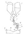
このような問題点を改善する装入装置として、特開昭49−23111 号公報に旋回ローテーション装置に先端部の位置可変機構とシュート先端部に原料整流用垂直シュートを装着したものが開示された。
図4は該特許公開公報に開示された原料装入装置の模式図を示したものであり、シュートローテーション装置11に垂直シュート4が取り付けてある。この垂直シュート4に取り付けた支持部材19にピン20を介して親シュート5aを支持させ、さらに親シュート5aを摺動する子シュート5bを取付ける。この子シュート5bの先端にピン21を介して原料整流用シュート7aを支持させて旋回シュートを形成するものである。
【0007】
子シュート5bは親シュート5aに沿って前後進することができるようになっており、垂直シュート4から落下する原料は親シュート5aに受け入れた後、子シュート5bを辷り落ちながら原料整流用シュート7aを介して高炉8内に装入される。
この時、炉内に装入される原料の炉半径方向の投入位置調整は親シュート5aに沿って子シュート5bを前後に摺動させることによって行われる。
【0008】
しかしながら、図4に示す特開昭49−23111 号公報に開示の炉頂装入装置では、上記のような問題点は軽減し、
(1)円周方向での落下位置の均一化
(2)狭い落下幅による原料装入
(3)垂直落下による原料装入前の原料表面高さによらない落下位置の均一化
が実現したが、
(1)旋回ローテーション装置の先端部に配設された子シュートの位置可変機構は構造状複雑なものが必要であり、高温でダストの多い環境化に置かれる装置としては保守管理が煩雑なものとなる。
(2)V字型またはM字型をした炉内装入物の旧推積面に新たに装入する粒子群が炉半径方向全体に高精度で分布させうるためには原料整流用シュートは垂直下方向からある適正な角度をもってずれている方が好ましい。
(3)旋回シュート自体を垂直方向に立てることができないため、堅型炉の中心部のみに装入物を分布させるような特殊装入をおこなうことができない。
(4)シュートが回転する際に生じる旋回シュートの向きとホッパ位置との配置関係の変化や、装入物粒子群の旋回シュート上でのすべり速度のバラツキによって生じる装入物装入量速度の時間変化(バラツキ)を防止することができない。
(5)炉半径方向の速度成分の消去が不十分なため、目的とする落下位置に推積させる精度に改善の余地がある。
等の問題点があった。
【0009】
【発明が解決しようとする課題】
この発明は、以上の問題点を解決する、すなわち、
(1)装入装置自体ができうる限りシンプルな構造のものであり、
(2)V字型またはM字型をした炉内装入物の旧推積面に対して原料整流用シュートを適正な角度をもって傾斜さすことが可能であり、
(3)旋回シュート自体を垂直方向に立てずに堅型炉の中心部のみに装入物を分布させるような特殊装入をおこなうことができ、
(4)シュートが回転する際に生じる旋回シュートの向きとホッパ位置との配置関係の変化や、装入物粒子群の旋回シュート上でのすべり速度のバラツキによって生じる装入物装入量速度の時間変化(バラツキ)を防止することができる、
(5)より精度良く目的とする落下位置に推積させる、
堅型炉用ベルレス式炉頂装入装置を提供することを目的とするものである。
【0010】
【課題を解決するための手段】
前記目的を達成するための請求項1記載の本発明は、炉頂ホッパの下部に設けた流量調整ゲートを用いて排出された原料を導く垂直シュートと、この垂直シュートの下部に設けた第1連結ピンを介して駆動により傾動自在に一端部を支持された旋回シュートと、この旋回シュートの他端部に設けた第2連結ピンを介して支持された原料整流用シュートとを備えた堅型炉用ベルレス式炉頂装入装置において、前記第1連結ピンと第2連結ピンとを結ぶ直線に交叉させてリンクロッドを配設し、当該リンクロッドの一端部を第3連結ピンを介して垂直シュートに連結する一方、他端部を第4連結ピンを介して原料整流用シュートに連結して作動用リンク機構を形成し、当該作動用リンク機構のリンクロッドを介して前記旋回シュートの傾動駆動力を原料整流用シュートに伝達し、原料整流用シュートの傾動角度を原料中心装入のときには鉛直下方線に対して炉中心方向寄りに、また原料周辺装入のときには鉛直下方線に対して炉壁方向寄りに傾動するように構成したことを特徴とする堅型炉用ベルレス式炉頂装入装置である。
【0012】
請求項2記載の本発明は、原料整流用シュートに連結するリンクロッドの垂直シュート側における第3連結ピンの固定位置を可動し得る構造とすることにより、炉操業中に原料整流用シュートの傾動角を変更できるように構成したことを特徴とする請求項1記載の堅型炉用ベルレス式炉頂装入装置である。
【0013】
【作用】
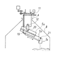
図1は本発明の請求項1に対応するベルレス式炉頂装入装置の模式図であり、2基の炉頂ホッパ1の下部にそれぞれ配設された流量調整ゲート2を用いて排出された原料6を導く集合シュート3を備えた垂直シュート4と、この垂直シュート4の下部に第1連結ピン11を介して駆動により傾動自在に一端部を支持された旋回シュート5と、この旋回シュート5の他端部に設けた第2連結ピン12を介して支持された原料整流用シュート7とを備えている。
【0014】
本発明では、上記第1連結ピン11と第2連結ピンとを結ぶ直線Aに交叉させてリンクロッド10を配設し、このリンクロッド10の一端部を第3連結ピン13を介して垂直シュート4に連結する一方、他端部を第4連結ピン14を介して原料整流用シュート7に連結して作動用リンク機構を形成する。
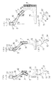
【0020】
図2は、請求項1記載の本発明に対応する旋回シュート5の傾斜角度θを変更しながら原料6を装入する手順を示している。図2においては、第1連結ピン11と第2連結ピン12とを結ぶ直線Aに交叉するようにリンクロッド10を配設し、このリンクロッド10の一端部を、第1連結ピン11の上方に位置する第3連結ピン13を介して垂直シュート4に連結する一方、他端部を第2連結ピン12の下方に位置する第4連結ピン14を介して原料整流用シュート7に連結して作動用リンク機構を形成する。
【0021】
リンクロッド10を用いて形成された作動用リンク機構を介して旋回シュート5を傾動させる傾動駆動装置(図示せず)の駆動力をリンクロッド10によって原料整流用シュート7に伝達し、これによって原料整流用シュート7の傾斜角度θ1 を変更するものである。
すなわち、図2の(a)に示すように旋回シュート5の傾斜面を流れる原料6を炉内装入物15の炉中心部近傍に装入する場合には旋回シュート5の傾斜角度θを小さくしてあるので垂直シュート4により固定されている第1連結点11および第3連結点13を起点にして移動する第2連結点12および第4連結点14は図2の(a)′に示すように第1連結ピン11と第2連結ピン12とを結ぶ直線Aに対してリンクロッド10の交叉点Cが図2の(a)′に示すように上部に位置する状態となって原料整流用シュート7はリンクロッド10により鉛直方向に対して中心方向寄りに傾斜する。
【0022】
また炉内装入物15の炉半径方向中間部に装入する場合には旋回シュート5の傾斜角度θを少しづつ大きくして行くとリンクロッド10により原料整流用シュート7の傾斜角度θ1 が小さくなり、図2の(b)に示すように原料整流用シュート10は鉛直(θ1 =0)状態になり炉中径方向の中間部に原料6が装入される。さらに旋回シュート5の傾斜角度θが大きくなるように傾動するとリンクロッド10により原料整流用シュート7は反対側の高炉8の炉壁方向に傾動し、図2の(c)に示すように傾斜角度θ2 をもって原料6は周辺装入となる。
【0023】
この場合、直線Aとリンクロッド10の交点Cは図2の(a)′、(b)′、および(c)′に示すように次第に下方に移動しながら原料整流用シュート7の装入物排出方向を中心装入のときには鉛直下方線に対して中心方向寄りに、また周辺装入のときには鉛直下方線に対して炉壁方向寄りに傾動するようにすることが可能となる。それゆえこの場合には、旋回シュート自体を垂直方向に立てずに堅型炉の中心部のみに装入物を分布させるような特殊装入をおこなうことができ、また、旋回シュートの長さが炉頂部の炉半径に比して短くても炉壁周辺にまで装入物を推積させることが可能となる。
【0024】
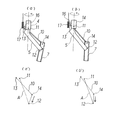
図3は、請求項2記載の本発明に対応する実施態様を示す模式図であり、一定長さのリンクロッド10の一端部に設けた連結ピン13を垂直シュート4に沿って上下方向に移動可能な機構とするものである。その上下移動機構は特定しないが、たとえば垂直シュート4の側面に、その上下方向に向けガイド(図示せず)を設け、このガイドに嵌る昇降ブロック16を配設する。そして昇降ブロック16にリンクロッド10を連結する連結ピン13を設けると共に昇降ブロック16を上方から垂下した昇降装置17により昇降させるようにする。
【0025】
図3の(a)に示すように昇降装置17により連結ピン13を備える昇降ブロック16を垂直シュート4の下端部に位置させたときにはリンクロッド10を介して原料整流用シュート7は鉛直下方に対して炉中心方向寄りに傾動する。また昇降ブロック16を垂直シュート4の高さ方向中間部に位置させたときにはリンクロッド10を介して原料整流用シュート7はほぼ鉛直状態に傾動する。さらに昇降ブロック16を垂直シュート4の上端部に位置させたときにはリンクロッド10を介して原料整流用シュート7は鉛直下方に対して炉壁方向寄りに傾動する。
【0026】
このような昇降ブロック16が垂直シュート4の下端部から中間部、さらには上端部に移動すると図3の(a)′および(b)′に示すように原料整流用シュートの原料排出方向を炉操業中において自由に変更することが可能となる。
【0027】
それゆえこの場合には、上記図2に示す本発明に比して、より極端に旋回シュート自体を垂直方向に立てずに堅型炉の中心部のみに装入物を分布させるような特殊装入をおこなうことができ、また、旋回シュートの長さが炉頂部の炉半径に比して極端に短くても炉壁周辺にまで装入物を推積させることが可能となる。
【0033】
【実施例】
内容積 4500Nm3のベルレス式炉頂装入装置を持つ高炉における改善効果を示す。旋回シュート長4mの先端に長さ約 1.5m、内径 0.5mの原料整流用シュートを駆動用のリンクロッドと共に図2のように取り付けた。
【0035】
次に、図2に示すように旋回シュートの傾動角が小さい時は原料整流用シュートが炉中心側を、旋回シュートの傾動角が大きい時は原料整流用シュートが炉壁側を向くようにリンク長さと原料整流用シュートとの接続位置を変更して操業を行った。
【0036】
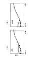
図5に中心部にコークスを集中的に装入した場合の、装入物の推積形状を示す。図5の(a)に示すように従来はコークスの落下位置が中心から外れていたが、図5の(b)に示すように本発明によりコークスは中心部に推積するようになった。
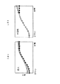
図6に炉壁部に細粒鉱石を装入する前後での推積形状を示す。原料整流用シュートが炉壁側を向くことにより、図6の(a)に示す従来例に比較し、(b)に示す本発明では、細粒鉱石が平坦部に確実に乗るようになり、中心部へ流入しなくなった。
【0037】
以上の実施例による本発明の効果により、中心ガス流制御精度が向上した。中心部温度は本発明実施後は安定し、しかも高めに推移している。また、ΔP/Vも低下し安定した。このため減風頻度が減少し、溶銑製造コストを低下させることができた。また、原料整流用シュートに連結するリンクの他端の固定位置を可変とし、炉中心部、炉壁部に装入した場合は、さらに中心装入、炉壁装入が可能となった。
【0044】
【発明の効果】
以上説明したように本発明によれば、以下の効果を達成することができる。
【0045】
旋回シュートの傾動力をリンクにより原料整流用シュートに伝えることにより、原料整流用シュートを特別な駆動装置無しに旋回シュートの傾動角に対応した指定方向にすることができる。その結果として、安価な投資コストで製銑製造コストを低下させることができた。
【図面の簡単な説明】
【図1】本発明の炉頂装入装置を断面で示す模式図である。
【図2】本発明のリンクロッド交叉型リンク機構による原料整流用シュートを介する原料装入手順を示す説明図である。
【図3】本発明のリンクロッド位置可変型リンク機構による原料整流用シュートを介する原料装入手順を示す説明図である。
【図4】従来の炉頂装入装置を示す模式図である。
【図5】中心部にコークスを集中的装入する場合の前後での装入物推積形状を従来例と本発明例とを比較して示すグラフである。
【図6】炉壁部に細粒鉱石を装入する前後での装入物推積形状を従来と本発明とを比較して示すグラフである。
【符号の説明】
1 炉頂ホッパ
2 流量調整ゲート
3 集合シュート
4 垂直シュート
5 旋回シュート
6 原料
7 原料整流用シュート
8 高炉
10 リンクロッド
11 第1連結ピン
12 第2連結ピン
13 第3連結ピン
14 第4連結ピン
15 炉内装入物
16 昇降ブロック
17 昇降装置
19 支持部材
20 ピン
21 ピン [0001]
[Industrial applications]
The present invention relates to a bellless for a rigid furnace, which is arranged on a furnace top of a blast furnace or the like and is capable of optimizing a raw material distribution in a furnace radial direction which is charged into a furnace through a swirling chute having a variable swirling radius. The present invention relates to a furnace top charging device.
[0002]
[Prior art]
In operation of the blast furnace as a hard-type furnace, the distribution of the raw material charge (coke and ore) at the furnace top portion radially, i.e. the particle size distribution and thickness distribution (L O / L C: L O is The ore layer thickness, L C is the coke layer thickness) is properly controlled to obtain gas flow distribution, heat flow ratio distribution (ratio of heat capacity flow rate of solid to heat capacity flow rate of gas), and the resulting reduction of ore. It is important to make the dissolution state uniform in the circumferential direction and to have an optimal distribution in the radial direction. For this purpose, it is necessary to flexibly control the distribution of the charge at the furnace top with high precision in response to the constantly changing operating state of the blast furnace.
[0003]
As a means for controlling the distribution of the charged material at the furnace top, a bell-type charging device has been conventionally known, and the distribution of the charged material such as coke and ore is determined by a stock line and a charged amount of I batch. The optimization was performed in consideration of the falling motion of the charged particles, the reflection on the armor, and the rolling behavior on the charged surface depending on the charging sequence, the position of the movable armor, and the like.
[0004]
Further, as a distribution control means for increasing the degree of freedom of the distribution control of the raw material charge, there is a bell-less swivel chute, and various kinds of distribution control are realized by changing the number of turns of the swivel chute and the angle of the swivel chute. Was.
However, in any of the above charging means, the charged particles are placed on the sliding surface of the charging device (in the case of a bell type, the sliding surface of a bell cup, and in the case of a bellless charging device, the sliding surface of a turning chute). Along the sliding surface, dropped freely from the tip of the sliding surface, and passed through rolling motion on the pile to determine the layer thickness and the particle size distribution.
[0005]
However, such a method of controlling the distribution of the burden is
(1) Since the free fall distance is long, there is a risk of powdering when dropped.
(2) Since the free-fall direction is the extension direction of the slip surface, a strong centrifugal inertia force at the time of drop breaks the previous charging surface and changes the layer thickness distribution.
(3) In the case of (2), the charged particles may be classified in the radial direction by the particle size distribution of the charged material forming the old piled surface.
(4) Further, when the charging amount of the I-batch is changed or the height of the old piling surface (stock line) is changed, the distribution of the charged material is extremely changed and the stability against disturbance is poor.
(5) The raw material drop position cannot be estimated accurately.
There were problems such as.
[0006]
As a charging device for solving such a problem, Japanese Patent Application Laid-Open No. 49-2311 discloses a rotating rotation device in which a position variable mechanism at the tip and a vertical chute for material rectification are mounted at the tip of the chute. .
FIG. 4 is a schematic view of a raw material charging device disclosed in the above-mentioned patent publication, and a
[0007]
The
At this time, the adjustment of the feeding position of the raw material charged in the furnace in the furnace radial direction is performed by sliding the
[0008]
However, in the furnace top charging apparatus disclosed in JP-49-23111 discloses that shown in FIG. 4, above problems are reduced,
(1) Uniform drop position in the circumferential direction (2) Raw material loading by narrow falling width (3) Uniform drop position by vertical falling regardless of raw material surface height before raw material loading ,
(1) The mechanism for changing the position of the child chute disposed at the tip of the turning rotation device requires a complicated structure, and as a device placed in a high-temperature, dusty environment, maintenance management is complicated. It becomes.
(2) The raw material rectification chute is vertical so that particles to be newly charged on the old piled surface of the V-shaped or M-shaped furnace interior material can be distributed with high accuracy over the entire furnace radial direction. it is preferable that not have the proper angle from the downward direction.
(3) Since the swivel chute itself cannot be set up in the vertical direction, it is not possible to perform special charging such that the charge is distributed only in the center of the rigid furnace.
(4) The change in the positional relationship between the direction of the turning chute and the hopper position generated when the chute rotates, and the change in the charging rate of the charge caused by the variation in the slip velocity of the charged particles on the turning chute. Time change (variation) cannot be prevented.
(5) Since the elimination of the velocity component in the furnace radial direction is insufficient, there is room for improvement in the accuracy of accumulating at the target drop position.
There were problems such as.
[0009]
[Problems to be solved by the invention]
The present invention solves the above problems, that is,
(1) The charging device itself has a structure as simple as possible,
(2) It is possible to incline the raw material rectification chute at an appropriate angle with respect to the old piled surface of the V-shaped or M-shaped furnace interior charge,
(3) It is possible to perform a special charge such that the charge is distributed only in the center of the rigid furnace without setting the turning chute itself in the vertical direction,
(4) The change in the positional relationship between the direction of the turning chute and the hopper position generated when the chute rotates, and the change in the charging rate of the charge caused by the variation in the slip velocity of the charged particles on the turning chute. Time change (variation) can be prevented,
(5) Accumulate more accurately at the target drop position.
It is an object of the present invention to provide a bellless furnace top charging device for a rigid furnace.
[0010]
[Means for Solving the Problems]
According to the first aspect of the present invention, there is provided a vertical chute for guiding a raw material discharged using a flow rate adjusting gate provided at a lower part of a furnace top hopper, and a first chute provided at a lower part of the vertical chute. A rigid type having a turning chute supported at one end so as to be tiltable by driving via a connecting pin, and a raw material rectification chute supported via a second connecting pin provided at the other end of the turning chute. In a bellless type furnace top charging apparatus for a furnace, a link rod is disposed so as to intersect a straight line connecting the first connecting pin and the second connecting pin, and one end of the link rod is vertically chuted via the third connecting pin. While the other end is connected to a raw material rectifying chute via a fourth connecting pin to form an operating link mechanism, and the tilting driving force of the turning chute is provided via a link rod of the operating link mechanism. Transmitted to the raw material rectification chute, the furnace wall direction with respect to the vertical downward direction line when the tilt angle of the material rectification chute into the furnace center direction closer to the vertical downward line when the raw material center charging, also material surrounding charged A bellless type furnace top charging device for a rigid furnace, characterized in that the device is configured to be tilted closer .
[0012]
According to the second aspect of the present invention, the fixed position of the third connection pin on the vertical chute side of the link rod connected to the raw material rectification chute can be moved, so that the raw material rectification chute can be tilted during the furnace operation. it is a hard-type furnace for bell-less furnace ItadakiSo inserting apparatus according to claim 1 Symbol placement, characterized by being configured to be able to change the angle.
[0013]
[Action]
FIG. 1 is a schematic view of a bell-less type furnace top charging apparatus according to claim 1 of the present invention, wherein the gas is discharged using flow rate control gates 2 respectively disposed below two furnace top hoppers 1. A
[0014]
In the present invention, the
[0020]
FIG. 2 shows a procedure for charging the
[0021]
The driving force of a tilt driving device (not shown) for tilting the turning
That is, when charging the
[0022]
In addition, when the slanting angle θ of the revolving
[0023]
In this case, the intersection C of the straight line A and the
[0024]
FIG. 3 is a schematic view showing an embodiment corresponding to the present invention described in claim 2, wherein a connecting
[0025]
Raw rectification chute 7 via a
[0026]
Intermediate portion
[0027]
Therefore, in this case, as compared with the present invention shown in FIG. 2, the special equipment such as distributing the charge only in the center of the rigid furnace without setting the swivel chute itself in the vertical direction is extremely extreme. Even if the length of the swirling chute is extremely short as compared with the radius of the furnace at the furnace top, it is possible to accumulate the charge around the furnace wall .
[0033]
【Example】
Shows the improvement in blast furnace having a bell-less furnace ItadakiSo inserting apparatus of the inner volume of 4500 nm 3. A length of about 1.5m on the tip of the turning chute length 4m, attached to the link rod and co for driving the feed rectification chute having an inner diameter of 0.5m as shown in FIG.
[0035]
Link to next, raw material rectification chute furnace center side when the tilt angle is small, the turning chute as shown in FIG. 2, as a raw material rectifier chute when a large tilting angle of the turning chute faces the furnace wall side The operation was performed by changing the length and the connection position of the raw material rectification chute.
[0036]
FIG. 5 shows the accumulated shape of the charge when coke is intensively charged at the center. Although the conventional as shown in FIG. 5 (a) falling position of the coke had been off-center, coke began to推積the heart by the present invention as shown in FIG. 5 (b).
FIG. 6 shows the piled shape before and after charging the fine ore into the furnace wall. By raw rectification chute faces the furnace wall side, compared with the conventional example shown in (a) of FIG. 6, in the present invention shown in (b), fine ore is to ride securely on the flat portion, Stopped flowing into the center.
[0037]
By the effect of the present invention by the above-described real施例was improved core gas flow control accuracy. The temperature at the center is stable after the present invention has been performed, and has been relatively high. Further, ΔP / V also decreased and became stable. For this reason, the frequency of wind reduction was reduced, and the manufacturing cost of hot metal could be reduced. In addition, when the fixed position of the other end of the link connected to the raw material rectification chute is made variable and inserted into the furnace center and the furnace wall, the center charging and the furnace wall charging can be further performed.
[0044]
【The invention's effect】
As described above, according to the present invention, the following effects can be achieved .
[0045]
By transmitting the tilting force of the swivel chute feed rectification chute by a link, the raw material rectification chute can be specified direction corresponding to the tilt angle of the turning chute to a special drive without. As a result, it was possible to lower the iron making cost with a low investment cost .
[Brief description of the drawings]
FIG. 1 is a schematic view showing a furnace top charging device of the present invention in cross section.
FIG. 2 is an explanatory view showing a raw material charging procedure via a raw material rectifying chute by a link rod crossing type link mechanism of the present invention.
FIG. 3 is an explanatory view showing a raw material charging procedure via a raw material rectifying chute by a link rod position variable link mechanism of the present invention.
FIG. 4 is a schematic view showing a conventional furnace top charging device.
FIG. 5 is a graph showing a comparison between a conventional example and an example of the present invention in terms of the charged material accumulation shape before and after the case where coke is intensively charged in the center.
FIG. 6 is a graph showing a comparison between the prior art and the present invention in terms of the charge accumulation shape before and after charging the fine ore into the furnace wall .
[Explanation of symbols]
1 furnace top hopper 2 flow rate control gate 3
10 Link rod
11 1st connection pin
12 Second connection pin
13 Third connection pin
14 4th connecting pin
15 Furnace interior
16 Lift block
17 lifting equipment
19 support members
20 pins
21 pin
Claims (2)
Priority Applications (1)
| Application Number | Priority Date | Filing Date | Title |
|---|---|---|---|
| JP32728593A JP3552257B2 (en) | 1993-12-24 | 1993-12-24 | Bell-less furnace top charging device for rigid furnaces |
Applications Claiming Priority (1)
| Application Number | Priority Date | Filing Date | Title |
|---|---|---|---|
| JP32728593A JP3552257B2 (en) | 1993-12-24 | 1993-12-24 | Bell-less furnace top charging device for rigid furnaces |
Publications (2)
| Publication Number | Publication Date |
|---|---|
| JPH07179916A JPH07179916A (en) | 1995-07-18 |
| JP3552257B2 true JP3552257B2 (en) | 2004-08-11 |
Family
ID=18197421
Family Applications (1)
| Application Number | Title | Priority Date | Filing Date |
|---|---|---|---|
| JP32728593A Expired - Fee Related JP3552257B2 (en) | 1993-12-24 | 1993-12-24 | Bell-less furnace top charging device for rigid furnaces |
Country Status (1)
| Country | Link |
|---|---|
| JP (1) | JP3552257B2 (en) |
Families Citing this family (5)
| Publication number | Priority date | Publication date | Assignee | Title |
|---|---|---|---|---|
| DE19929180C2 (en) * | 1999-06-25 | 2001-08-09 | Zimmermann & Jansen Gmbh | Feeding device for a shaft furnace |
| KR100733356B1 (en) * | 2001-05-18 | 2007-06-29 | 주식회사 포스코 | Furnace reinforcement input device |
| LU91176B1 (en) * | 2005-06-15 | 2006-12-18 | Wurth Paul Sa | Charging device and distribution chute for a shaftfurnace |
| JP2012076275A (en) * | 2010-09-30 | 2012-04-19 | Toray Ind Inc | Powder material supply device, and method of manufacturing thermoplastic resin composition |
| KR101875148B1 (en) * | 2016-12-13 | 2018-07-06 | 주식회사 포스코 | Apparatus for charging |
-
1993
- 1993-12-24 JP JP32728593A patent/JP3552257B2/en not_active Expired - Fee Related
Also Published As
| Publication number | Publication date |
|---|---|
| JPH07179916A (en) | 1995-07-18 |
Similar Documents
| Publication | Publication Date | Title |
|---|---|---|
| US4243351A (en) | Method of and apparatus for charging a furnace | |
| JP3552257B2 (en) | Bell-less furnace top charging device for rigid furnaces | |
| WO2001067017A1 (en) | Device for charging material into sintering machine | |
| JP3975692B2 (en) | Distribution chute structure of bellless type furnace top charging equipment for blast furnace. | |
| JPS6339641B2 (en) | ||
| KR100471369B1 (en) | Slewing Shute for Charging Apparatus | |
| JP3772377B2 (en) | Rotating chute for bellless type furnace top charging equipment for blast furnace | |
| JP3823485B2 (en) | Rotating chute for bellless type furnace top charging equipment for blast furnace | |
| JP5493885B2 (en) | Rotating chute for bellless type furnace top charging equipment for blast furnace | |
| JP3787240B2 (en) | How to charge the blast furnace center | |
| JP3787238B2 (en) | Charging method into the center of the blast furnace | |
| JPH09235604A (en) | Bellless furnace top charging device for blast furnace | |
| JPH08350Y2 (en) | Adjustment device for time-series particle size characteristics from hopper | |
| CN116710577B (en) | Method for charging raw materials into blast furnace | |
| JPH02195193A (en) | Charge device of sintered material | |
| KR101875148B1 (en) | Apparatus for charging | |
| JP7264186B2 (en) | Furnace top bunker and blast furnace raw material charging method | |
| JPS6314808A (en) | Raw material charging method for bell-less type blast furnace | |
| JP3787231B2 (en) | How to charge the blast furnace center | |
| KR100393758B1 (en) | Control method for sectional classified by burden material of blast furnace | |
| JPS62260009A (en) | Charging method for pellet-compounded raw material in bell-less type blast furnace | |
| JP2000204407A (en) | Method of charging the charge in the center of the blast furnace | |
| JP2754617B2 (en) | Raw material charging method for bell blast furnace | |
| JPS62218507A (en) | Raw material charging method for bell-less blast furnace | |
| JP2996803B2 (en) | Blast furnace operation method by bellless blast furnace |
Legal Events
| Date | Code | Title | Description |
|---|---|---|---|
| A131 | Notification of reasons for refusal |
Free format text: JAPANESE INTERMEDIATE CODE: A131 Effective date: 20040203 |
|
| A521 | Written amendment |
Free format text: JAPANESE INTERMEDIATE CODE: A523 Effective date: 20040318 |
|
| TRDD | Decision of grant or rejection written | ||
| A01 | Written decision to grant a patent or to grant a registration (utility model) |
Free format text: JAPANESE INTERMEDIATE CODE: A01 Effective date: 20040413 |
|
| A61 | First payment of annual fees (during grant procedure) |
Free format text: JAPANESE INTERMEDIATE CODE: A61 Effective date: 20040426 |
|
| R150 | Certificate of patent or registration of utility model |
Free format text: JAPANESE INTERMEDIATE CODE: R150 |
|
| LAPS | Cancellation because of no payment of annual fees |