JP3547845B2 - Injection speed control method and apparatus for injection molding machine - Google Patents
Injection speed control method and apparatus for injection molding machine Download PDFInfo
- Publication number
- JP3547845B2 JP3547845B2 JP10090595A JP10090595A JP3547845B2 JP 3547845 B2 JP3547845 B2 JP 3547845B2 JP 10090595 A JP10090595 A JP 10090595A JP 10090595 A JP10090595 A JP 10090595A JP 3547845 B2 JP3547845 B2 JP 3547845B2
- Authority
- JP
- Japan
- Prior art keywords
- injection
- speed
- plunger
- value
- deceleration
- Prior art date
- Legal status (The legal status is an assumption and is not a legal conclusion. Google has not performed a legal analysis and makes no representation as to the accuracy of the status listed.)
- Expired - Fee Related
Links
Images


Classifications
-
- B—PERFORMING OPERATIONS; TRANSPORTING
- B29—WORKING OF PLASTICS; WORKING OF SUBSTANCES IN A PLASTIC STATE IN GENERAL
- B29C—SHAPING OR JOINING OF PLASTICS; SHAPING OF MATERIAL IN A PLASTIC STATE, NOT OTHERWISE PROVIDED FOR; AFTER-TREATMENT OF THE SHAPED PRODUCTS, e.g. REPAIRING
- B29C45/00—Injection moulding, i.e. forcing the required volume of moulding material through a nozzle into a closed mould; Apparatus therefor
- B29C45/17—Component parts, details or accessories; Auxiliary operations
- B29C45/76—Measuring, controlling or regulating
- B29C45/77—Measuring, controlling or regulating of velocity or pressure of moulding material
Landscapes
- Engineering & Computer Science (AREA)
- Manufacturing & Machinery (AREA)
- Mechanical Engineering (AREA)
- Injection Moulding Of Plastics Or The Like (AREA)
Description
【0001】
【産業上の利用分野】
本発明は、射出成形機における射出速度制御方法および装置に関するものであり、特に充填工程より保圧工程への切換区間における射出プランジャの減速制御を行う射出速度制御方法および装置に関するものである。
【0002】
【従来の技術】
射出成形機において、射出プランジャ(スクリュ)の位置に応じて射出プランジャの前進速度を予め設定されたプロファイルに従ってプログラム制御することは従来より行われている。
【0003】
従来、この射出速度のプロクラム制御は、一般に、図10に例示されているように、射出プランジャの充填ストロークを複数個に区分し、その各区間毎に前進速度V1 、V2 、V3 、V4 を指定して多段の矩形プロファイルを設定し、射出プランジャの前進速度を、射出プランジャの位置に対し、矩形プロファイルで設定した速度V1 、V2 、V3 、V4 により制御する。
【0004】
この速度プロクラム制御のプロファイルの後半部分の速度V3 、V4 は、金型内樹脂流路に溶融樹脂が充満する充填完了時点の手前で、射出プランジャの前進を減速させ、金型内の溶融樹脂圧力に異常な高圧力を発生させない制御のための設定であり、充填完了手前の射出プランジャの減速制御を行うものである。
【0005】
このように射出プランジャの前進速度が設定されると、射出プランジャの前進のための駆動力PAは、図10に示されているように変化する。
【0006】
速度プロクラム制御のプロファイルの後半部分の速度V3 、V4 は、的確に減速を行い、しかも過剰減速によって充填中に金型末端付近の樹脂が過度に冷却されることを防ぐと云う前提条件のもとに、成形品の形状に応じて、また成形に使用する樹脂原料の物性に応じて過不足なく設定されることを要求される。
【0007】
従来、速度V3 、V4 による減速制御特性の設定は、多くの場合、作業者の経験則により試行錯誤のもとに行われている。
【0008】
【発明が解決しようとする課題】
的確に減速を行い、しかも過剰減速によって充填中に金型末端付近の樹脂が過度に冷却されることを防ぐと云う条件を満たす減速制御特性の設定には、高度な成形ノウハウが必要であり、このことが成形条件設定作業を困難なものとしている。実際には試し打ち成形を数多く繰り返して妥協できる減速制御特性を設定しており、減速制御特性の設定には多くの時間がかかると云う問題がある。
【0009】
また射出プランジャの前進速度がV3 、V4 と段階的に減速したのでは、金型内の溶融樹脂圧力は、射出プランジャの前進のための駆動力PAの変動から解るように波打ち形状に変動し、必ずしも金型内の溶融樹脂圧力が健全に保たれない。この不具合を低減、回避するためには、減速区間におけるプランジャ前進速度の変化を多段にしたり、適当な減速関数によって逓減するような減速特性を設定する必要が生じる。しかし、このような設定はプロファイル設定作業をより一層難しいものにする。
【0010】
本発明は、このような問題点を解決することを目的としてなされたものであり、射出プランジャの減速制御特性が適切に設定されたか否かを自動的に判別し、更にはその判別結果に応じて減速制御特性を自動修正し、補正制御によって過不足がない適正な減速制御特性を自動設定する射出成形機の射出速度制御方法および装置を提供することを目的としている。
【0011】
【課題を解決するための手段】
上述の如き目的を達成するために、請求項1による射出成形機の射出速度制御方法は、成形に必要とされる量の計量された溶融樹脂を収容するための射出シリンダ内に進退可能に挿入された射出プランジャの、射出開始位置から保圧切換位置へ向けて前進させ、前記射出プランジャの前進駆動力を第一の検出手段によって検出し、この第一の検出手段で検出された検出値が前記保圧切換位置から射出開始位置へ向けて予め設定された前進駆動力比較有効区間内に予め設定した基準値を超えた時点で、射出プランジャの前進速度を予め定めた減速関数による減速制御プロファイルに従って減速制御し、前記前進駆動力比較有効区間の減速制御中の射出プランジャの前進速度を第二の検出手段によって検出し、この第二の検出手段で検出された検出値が予め設定されている上限値を上回っているか否かと前記検出値が予め設定されている下限値を下回っている否かの少なくとも何れか一方の判別を行い、前記検出値が前記上限値を上回っているか或いは前記検出値が前記下限値を下回っているかの少なくとも何れか一方の場合にアラーム信号を出力することを特徴としている。
【0012】
請求項2による射出成形機の射出速度制御方法は、請求項1に記載の射出成形機の射出速度制御方法において、前記前進駆動力比較有効区間において前記上限値と前記下限値の少なくとも何れか一方を減速制御特性に応じて連続的に、あるいは所定ピッチをもって多点に設定し、前記判別を前記前進駆動力比較有効区間において連続的に、あるいは多点にて行うことを特徴としている。
【0012】
請求項3による射出成形機の射出速度制御方法は、請求項1に記載の射出成形機の射出速度制御方法において、前記第二の検出手段による検出値が、前記前進駆動力比較有効区間において下限値を下回った場合には、同一成形サイクルにおけるそれ以降の前記射出プランジャの前進速度をその時点における前進速度に固定することを特徴としている。
【0013】
請求項4による射出成形機の射出速度制御方法は、請求項1〜3の何れかに記載の射出成形機の射出速度制御方法において、前記基準値が2個以上設定され、各基準値に対し異なる減速関数によって減速制御プロファイルを設定することを特徴としている。
【0014】
請求項5による射出成形機の射出速度制御方法は、請求項1〜4の何れかに記載の射出成形機の射出速度制御方法において、アラーム信号が出力された場合には、次の成形サイクルにおける前記基準値を修正することを特徴としている。
【0015】
請求項6による射出成形機の射出速度制御方法は、請求項1〜5の何れかに記載の射出成形機の射出速度制御方法において、アラーム信号が出力された場合には、減速制御プロファイルを設定する関数を変更して減速制御プロファイルを修正し、次の成形サイクルでは修正された減速制御プロファイルに従って射出プランジャを減速制御することを特徴としている。
【0016】
また上述の如き目的を達成するために、請求項7による射出成形機の射出速度制御装置は、成形に必要とされる量の計量された溶融樹脂を収容するための射出シリンダ内に進退可能に挿入された射出プランジャの、射出開始位置から保圧切換位置へ向けて前進させる駆動力を検出する第一の検出手段と、前記第一の検出手段による検出値が前記保圧切換位 置から前記射出開始位置へ向けて予め設定された前進駆動力比較有効区間内に予め設定した基準値を超えた時点で予め定めた減速関数による減速制御プロファイルに従って前記射出プランジャの前進速度を減速制御する減速制御手段と、前記射出プランジャの前進速度を検出する第二の検出手段と、前記前進駆動力比較有効区間において前記第二の検出手段によって検出される射出プランジャの前進速度が予め設定されている上限値を上回っているか否かと前記検出値が予め設定されている下限値を下回っている否かの少なくとも何れか一方の判別を行い、前記検出値が前記上限値を上回っているか或いは前記検出値が前記下限値を下回っているかの少なくとも何れか一方の場合にアラーム信号を出力するプランジャ速度判別手段とを有していることを特徴としている。
【0017】
請求項8による射出成形機の射出速度制御装置は、請求項7に記載の射出成形機の射出速度制御装置において、前記プランジャ速度判別手段がアラーム信号を出力した場合には、次の成形サイクルにおける前記基準値の修正、前記減速制御プロファイルの修正、前記基準値と前記第一の検出手段による検出値との比較を有効とする区間の変更の少なくとも何れか一つを行う制御要件修正変更手段を有していることを特徴としている。
【0018】
【作用】
請求項1、7による射出成形機の射出速度制御方法および装置では、第一の検出手段によって射出プランジャを前進させる駆動力を検出し、第一の検出手段による検出値が前記保圧切換位置から前記射出開始位置へ向けて予め設定された前進駆動力比較有効区間内に予め設定した基準値を超えた時点で、予め定めた減速関数による減速制御プロファイルに従って射出プランジャの減速制御を開始する。
【0019】
この前進駆動力比較有効区間において第二の検出手段により検出されるプランジャ前進速度が、予め設定されている上限値を上回っているか否かと、予め設定されている下限値を下回っているか否かの少なくとも何れか一方の判別を行い、プランジャ前進速度が上限値を上回っているか或いは下限値を下回っているかの少なくとも何れか一方の場合にアラーム信号を出力する。
【0020】
請求項2による射出成形機の射出速度制御方法では、前記前進駆動力比較有効区間において前記上限値と前記下限値の少なくとも何れか一方を減速制御特性に応じて連続的に、あるいは所定ピッチをもって多点に設定し、プランジャ前進速度が、予め設定されている上限値を上回っているか否かと、予め設定されている下限値を下回っているか否かの少なくとも何れか一方の判別を前記前進駆動力比較有効区間において連続的に、あるいは多点にて行う。
【0021】
請求項3による射出成形機の射出速度制御方法では、前進駆動力比較有効区間中においてプランジャ前進速度が上限値を上回った場合あるいは前記下限値を下回った場合には、同一成形サイクルにおけるそれ以降のプランジャ前進速度をその時点における前進速度に固定し、それ以上にプランジャ前進速度が不適切値になることを回避する。
【0022】
請求項4による射出成形機の射出速度制御方法では、減速制御を開始する基準値が2個以上設定され、各基準値に対し異なる減速関数によって減速制御プロファイルが設定される。
【0023】
請求項5による射出成形機の射出速度制御方法では、アラーム信号が出力されると、次の成形サイクルにおける前記基準値を修正する。
【0024】
請求項6による射出成形機の射出速度制御方法では、アラーム信号が出力されると、次の成形サイクルで使用する減速制御プロファイルを修正する。
【0025】
請求項8による射出成形機の射出速度制御装置では、アラーム信号が出力されると、制御要件修正変更手段によって、次の成形サイクルにおける前記基準値の修正、前記減速制御プロファイルの修正、前記基準値と前記第一の検出手段による検出値との比較を有効とする区間の変更の少なくとも何れか一つが行われる。
【0026】
【実施例】
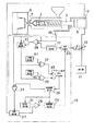
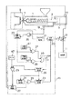
図1は本発明による射出速度制御装置を油圧式射出成形機に適用した実施例を示している。
【0027】
油圧式射出成形機は、成形に必要とされる量を計量された溶融樹脂を収容する射出シリンダ1と、射出シリンダ1内に進退可能に挿入されたスクリュによる射出プランジャ3と、射出プランジャ3を進退駆動する油圧シリンダ装置5とを有し、射出プランジャ3の前進により溶融樹脂をノズル7より金型9内へ射出する。
【0028】
油圧シリンダ装置5には油圧源11より圧油が流量制御弁13により流量を計量されつつ供給される。
【0029】
この場合、射出プランジャ3の前進速度は油圧シリンダ装置5に供給される圧油の流量により決まり、流量制御弁13による圧油の流量制御によって射出プランジャ3の前進速度が制御される。
【0029】
流量制御弁13は、圧油流量を定量的に制御する可変絞り式の電磁制御であり、射出速度設定装置15より速度指令信号を与えられて動作する。
【0030】
射出速度設定装置15には、射出プランジャ3の前進駆動力を油圧シリンダ装置5の油圧により検出する前進駆動力検出器17と、射出プランジャ3の移動位置を検出する位置検出器19とが接続されている。
【0031】
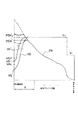
射出速度設定装置15は、図2に示されている速度設定値V1 、V2 による矩形の速度プログラム制御用のプロファイルを設定されたプログラム設定器21と、図2に符号VDにより示されているような所定の減速関数による減速制御プロファイルを設定する減速関数設定器23とを有し、信号切換器20よりプログラム設定器21と減速関数設定器23の何れかより速度指令信号を流量制御弁13へ出力する。
【0032】
比較器25は、現在のプランジャ位置がプランジャの前進駆動力比較有効区間Aの位置であるか否かを判別するものであり、減速制御設定器26に予め設定されたプランジャ移動位置による前進駆動力比較有効区間Aと位置検出器19により検出される射出プランジャ3の位置とを比較し、現在のプランジャ位置が前進駆動力比較有効区間Aになれば、回路開閉器27をオンさせる。
【0033】
回路開閉器27は、オン状態においてのみ前進駆動力検出器17が検出する射出プランジャ3の前進駆動力の検出信号を比較器29へ送信する。
【0034】
比較器29は、前進駆動力検出器17により検出された射出プランジャ3の前進駆動力が基準値設定器31により設定された基準値に達したか否かを判別し、前進駆動力が基準値に達した時には減速関数設定器23へ動作開始指令信号を出力する。
【0035】
減速関数設定器23は動作開始指令信号の入力によって減速制御設定器26の指令によって設定されている減速プロファイルによる速度指令信号を信号切換器20より流量制御弁13へ出力する。
【0036】
これに対し、プログラム設定器21は、比較器29が減速関数設定器23へ動作開始指令信号を出力するまで、即ち射出プランジャ3の前進駆動力が基準値設定器31により設定された基準値に達するまで、図2の速度設定値V1 、V2 を定義しているプロファイルによる速度指令信号を信号切換器20より流量制御弁13へ出力する。
【0037】
速度演算器33は位置検出器19が出力する検出値より射出プランジャ3の前進速度を演算する。
【0038】
比較器35は、位置検出器19が出力する検出値とプログラム設定器21に設定されている保圧切換位置とを比較し、保圧切換位置における射出プランジャ3の前進速度をラッチするために速度演算器33へラッチ信号を出力する。
【0039】
速度演算器33がラッチした保圧切換位置におけるプランジャ前進速度の信号は上限比較器37と下限比較器39に入力される。
【0040】
上限比較器37は、保圧切換位置におけるプランジャ前進速度が上限値設定器41に設定されている上限値を上回っているか否かを判別し、プランジャ前進速度が上限値を上回っていれば、オン信号をOR回路45へ出力する。
【0041】
下限比較器39は、保圧切換位置におけるプランジャ前進速度が下限値設定器43に設定されている下限値を下回っているか否かを判別し、プランジャ前進速度が下限値を下回っていれば、オン信号をOR回路45へ出力する。
【0042】
OR回路45は、上限比較器37と下限比較器39の何れかよりオン信号を入力することによりアラーム信号を出力する。
【0043】
このアラーム信号は減速制御設定器26にも出力され、減速制御設定器26は、アラーム信号の入力により、次の成形サイクルのために基準値設定器31による基準値の修正、減速関数設定器23に設定される減速関数の修正、比較器25に与える前進駆動力比較有効区間データの変更の少なくとも何れか一つを行い、制御要件修正変更手段として機能する。
【0044】
次に上述の如き構成よりなる射出速度制御装置の動作を図2を参照して説明する。
【0045】
充填工程が始まると、先ずプログラム設定器21に設定されている速度プログラム制御用のプロファイルが設定している前進速度V1 、V2 により速度指令信号が信号切換器20を経由して流量制御弁13へ送られる。これにより油圧源11より油圧シリンダ装置5に供給する圧油の流量が流量制御弁13により制御され、射出プランジャ3は、位置に応じて、図2に示されているプロファイルに従って前進速度をV1 、V2 と変化して前進する。
【0046】
この射出プランジャ3の前進により、前進駆動力検出器17により検出される射出プランジャ3の前進駆動力は、図2にて符号PAにより示されているように増加する。
【0047】
射出プランジャ3が減速制御設定器26に予め設定されているプランジャ前進駆動力の比較有効区間Aにまで移動すると、比較器25の出力信号により回路開閉器27がオン状態になり、前進駆動力検出器17が検出する射出プランジャ3の前進駆動力の検出信号が比較器29へ送信される。
【0048】
前進駆動力検出器17により検出された射出プランジャ3の前進駆動力が基準値設定器31により設定されている基準値PSHに達すると、比較器29が動作開始指令信号を減速関数設定器23へ出力することにより、減速関数設定器23が図2に符号VDにより示されているような減速プロファイルによる速度指令信号を信号切換器20より流量制御弁13へ出力する。
【0049】
これにより減速プロファイルVDによる減速制御が実行される。
【0050】
射出プランジャ3が保圧切換位置にまで前進すると、速度演算器33によって演算された保圧切換位置における射出プランジャ3の前進速度VSを示す信号が上限比較器37と下限比較器39へ送られる。
【0051】
上限比較器37では前進速度VSが上限値設定器41に設定されている上限値VAHを上回っているか否かの判別が行われ、下限比較器39では前進速度VSが下限値設定器43に設定されている下限値VALを下回っているか否かの判別が行われる。
【0052】
射出プランジャ3が保圧切換位置に達した時の前進速度VSが許容範囲VAL〜VAH内であれば、そのまま制御が継続される。
【0053】
これに対し前進速度VSが上限値設定器41に設定されている上限値VAHを上回っているか、あるいは下限値設定器43に設定されている下限値VALを下回っていれば、OR回路45がアラーム信号を出力する。
【0054】
このアラーム信号の出力の有無より、射出プランジャ3の減速制御が適切に行われたか否かが自動的に的確に判る。
【0055】
このアラーム信号の出力により、減速制御設定器26は、アラーム信号の入力により、基準値設定器31による基準値PSHの修正、減速関数設定器23に設定される減速関数の修正、比較器25に与える前進駆動力比較有効区間Aの変更の少なくとも何れか一つを行う。
【0056】
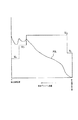
図2のグラフでは、射出プランジャ3の前進駆動力PAが基準値PSHに達した時、所定の減速関数により減速プロファイルVDに従った減速制御が行われ、保圧切換位置における射出プランジャ3の前進速度がVSとなっている。
【0057】
このVS値は下限値VALを下回っているので、減速制御設定器26によって基準値PSHより大きい新たな基準値PSH′が修正設定される。
【0058】
これにより次の成形サイクルでは、前進側にシフトされた減速プロファイルVD′に従って減速制御が行われ、保圧切換位置での射出プランジャ前進速度がVS′となって、適性範囲VAL〜VAH内に入るようになる。以後、基準値PSH′を減速制御開始点して速度制御が行われる。
【0059】
図2に示す本発明による射出速度制御方法、装置における速度プログラム自動設定の状況を、図10に示す従来例と比較すると、充填開始時の速度設定値V1 、V2 の設定は同一であるが、図10の従来例で設定している3段目以降の速度V3 、V4 は定義していない。
【0060】
これに代えて本発明による射出速度制御方法、装置における速度プログラム自動設定では、減速制御開始の基準値PSHと、保圧切換位置における射出プランジャ前進速度の上限値VAHと下限値VALを設定している。
【0061】
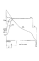
アラーム出力時には、基準値PSHの修正に代えて、図3に示されているように、減速関数設定器23に設定される減速関数を修正することにより、次の成形サイクルでは減速プロファイルをVDよりVD′に変更し、次の成形サイクルにおける保圧切換位置での射出プランジャ前進速度VS′が適性範囲VAL〜VHL内に入るようにしてもよい。
【0062】
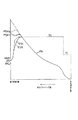
またこれ以外に、アラーム出力時には、図4に示されているように、比較器25に与える前進駆動力比較有効区間をAよりA′に変更することにより、減速プロファイルVDよる減速開始点を変更し、次の成形サイクルにおける保圧切換位置での射出プランジャ前進速度VS′が適性範囲VAL〜VAH内に入るようにしてもよい。
【0063】
これらの減速制御要件の修正、変更により、減速制御特性が自動的に最適化される。
【0064】
また基準値を2個以上選択可能に設定し、各基準値に対し異なる減速関数によって減速制御プロファイルを演算設定することもできる。この場合には、減速制御がより一層きめ細かく要求特性に適合した特性をもって行われ得るようになる。
【0065】
図5に示されたグラフでは、基準値PSH1 ではある所定の減速関数による減速プロファイルVD1 を設定し、基準値PSH2 では減速プロファイルVD1 の減速関数とは異なった減速関数による減速プロファイルVD2 を設定している。
【0066】
図6は本発明による射出速度制御装置を油圧式射出成形機に適用した他の実施例を示している。尚、図6に於いて、図1に対応する部分は図1に付した符号と同一の符号を付して説明を省略する。
【0067】
この実施例においては、減速制御設定器26にはプランジャ前進駆動力の比較有効区間が充填開始時からの経過時間により指定されており、比較器25は、タイマ47から送られるクロック信号と減速制御設定器26に指定されている比較有効時間とを比較し、比較有効時間になれば、回路開閉器27をオンさせる。
【0068】
この実施例では、プランジャ前進駆動力の比較有効区間が充填開始時からの経過時間によって設定されること以外は、上述の実施例と同一である。
【0069】
従って、この実施例においても上述の実施例と同様の作用が得られる。
【0070】
図7は本発明による射出速度制御装置を油圧式射出成形機に適用した他の実施例を示している。尚、図7に於いても、図1に対応する部分は図1に付した符号と同一の符号を付して説明を省略する。
【0071】
この実施例においては、減速制御設定器26より比較有効区間であることを示す信号あるいは比較器29より減速制御区間であることを示す信号が速度演算器33に与えられ、速度演算器33は、比較有効区間あるいは減速制御区間を与えられている間、位置検出器19が出力する検出値より射出プランジャ3の前進速度を演算する。速度演算器33により演算されたプランジャ前進速度の信号は下限比較器39に入力される。
【0072】
下限比較器39は、比較有効区間あるいは減速制御区間におけるプランジャ前進速度が下限値設定器43に設定されている下限値を下回っているか否かを判別し、プランジャ前進速度が下限値設定器43に設定されている下限値を下回っていれば、アラーム信号を出力する。なお、請求項の記載では、比較有効区間と減速制御区間とを総称して減速制御区間としている。
【0073】
このアラーム信号は減速制御設定器26にも出力され、減速制御設定器26は、アラーム信号の入力により、同一成形サイクルにおける射出プランジャのそれ以降の前進速度をその時点における前進速度に固定する指令と、次の成形サイクルのために基準値設定器31による基準値の修正、減速関数設定器23に設定される減速関数の修正、比較器25に与える前進駆動力比較有効区間データの変更の少なくとも何れか一つを行う。
【0074】
この実施例では、プランジャ前進速度が下限値設定器43に設定されている下限値を下回ると、同一成形サイクルにおける射出プランジャのそれ以降の前進速度が、その時点における前進速度に固定されるから、それ以上にプランジャ前進速度が低下することがなく、プランジャ前進速度がそれ以上に不適切値になることが回避される。
【0075】
図8は射出プランジャ速度の多段プロファイルを設定した場合の制御例である。V11、V12、V13、V14、V15のように速度を増減がある多段設定した場合、射出プランジャに要求される前進駆動力PAは、図示されるように増減を繰り返すような挙動を示す。
【0076】
この場合、前進駆動力PAが基準値PSHに達した時点で減速制御を開始させようとすると、点Pa、Pb、Pcの3点で、前進駆動力PAが基準値PSHに到達する。
【0077】
しかし実際に減速を開始させたいのは点Pcである。従ってこの場合には、射出プランジャを前進させる駆動力PAと基準値PSHとの比較を有効とする区間を点Peから点Phまでの区間に限定し、点Paから点Peまでの区間は、比較しない制御を行うことにより、点Pcから減速プロファイルVDによる減速制御が行われる。
【0078】
なお保圧切換点における射出プランジャの前進速度VSが許容範囲VAH〜VAL内であるか否かの判別、その後の減速制御要件の修正、変更などは図1の場合と同様に行われればよい。
【0079】
上述の何れの実施例においても、プランジャ前進速度の適否判別を保圧工程への切換位置の一点で行っているが、この適否判別は、減速制御区間において上限値VAHと下限値VALの少なくとも何れか一方を減速制御特性に応じて連続的に、あるいは所定ピッチをもって多点に設定し、射出プランジャ3の前進速度VSが、予め設定されている上限値VAHを上回っているか否かと、予め設定されている下限値VALを下回っている否かの少なくとも何れか一方の判別を減速制御区間において連続的に、あるいは最低2点の多点にて行われてもよい。
【0080】
図9は上述の判別を減速制御区間において連続的行う場合の射出プランジャの前進速度と前進駆動力との変化特性の一例を示している。この場合には、上限値と下限値は各々関数fにより、減速制御特性に適合するものとして、f(VAH)、f(VAL)とされ、図に示されているプログラム設定器21に予め設定される。
【0081】
これにより、減速制御区間において、射出プランジャ3の前進速度VSが適正範囲f(VAL)〜f(VAH)内であるか否かの判別がプランジャ位置に応じて連続的に行われ、射出速度制御がより一層的確に行われるようになる。
【0082】
【発明の効果】
以上の説明から理解される如く、請求項1、7による射出成形機の射出速度制御方法および装置では、第一の検出手段によって射出プランジャを前進させる駆動力を検出し、第一の検出手段による検出値が前記保圧切換位置から前記射出開始位置へ向けて予め設定された前進駆動力比較有効区間内に予め設定した基準値を超えた時点で、予め定めた減速関数による減速制御プロファイルに従って射出プランジャの減速制御を開始し、この前進駆動力比較有効区間において第二の検出手段により検出されるプランジャ前進速度が、予め設定されている上限値を上回っているか否かと、予め設定されている下限値を下回っているか否かの少なくとも何れか一方の判別を行い、プランジャ前進速度が上限値を上回っているか或いは下限値を下回っているかの少なくとも何れか一方の場合にアラーム信号を出力するから、射出プランジャの減速制御特性が適切に設定されたか否かが自動的に的確に判る。
【0083】
請求項2による射出成形機の射出速度制御方法では、前記前進駆動力比較有効区間において前記上限値と前記下限値の少なくとも何れか一方を減速制御特性に応じて連続的に、あるいは所定ピッチをもって多点に設定し、プランジャ前進速度が、予め設定されている上限値を上回っているか否かと、予め設定されている下限値を下回っている否かの少なくとも何れか一方の判別を前記前進駆動力比較有効区間において連続的に、あるいは多点にて行うから、前進駆動力比較有効区間における射出プランジャの前進速度が連続的に、あるいは多点にて監視され、射出速度制御がより一層的確に行われるようになる。
【0084】
請求項3による射出成形機の射出速度制御方法では、前進駆動力比較有効区間中においてプランジャ前進速度が下限値を下回った場合には、同一成形サイクルにおけるそれ以降のプランジャ前進速度をその時点における前進速度に固定するから、それ以上にプランジャ前進速度が不適切値になることを回避できる。
【0085】
請求項4による射出成形機の射出速度制御方法では、減速制御を開始する基準値が2個以上設定され、各基準値に対し異なる減速関数によって設定された減速制御プロファイルに従って射出プランジャの前進速度を減速制御するから、減速制御がより一層きめ細かく要求特性に適合して特性をもって行われ得るようになる。
【0086】
請求項5による射出成形機の射出速度制御方法では、アラーム信号が出力されると、次の成形サイクルにおける前記基準値を修正するから、減速制御を開始する基準値が補正制御により適正値に変更され、成形ノウハウを必要とすることなく減速制御特性を自動的に最適化することができる。
【0087】
請求項6による射出成形機の射出速度制御方法では、アラーム信号が出力されると、次の成形サイクルで使用する減速制御プロファイルを修正するから、減速制御プロファイルが補正制御により適正値に変更され、成形ノウハウを必要とすることなく減速制御特性を自動的に最適化することができる。
【0088】
請求項8による射出成形機の射出速度制御装置では、アラーム信号が出力されると、制御要件修正変更手段によって、次の成形サイクルにおける前記基準値の修正、前記減速制御プロファイルの修正、前記基準値と前記第一の検出手段による検出値との比較を有効とする区間の変更の少なくとも何れか一つが行われ、これらの学習制御により成形ノウハウを必要とすることなく減速制御特性を自動的に最適化することができる。
【図面の簡単な説明】
【図1】本発明による射出速度制御装置を油圧式射出成形機に適用した実施例を示す一実施例を示すブロック線図である。
【図2】本発明による射出成形機の射出速度制御方法による場合の射出プランジャの前進速度と前進駆動力との変化特性の一例を示すグラフである。
【図3】本発明による射出成形機の射出速度制御方法による場合の射出プランジャの前進速度と前進駆動力との変化特性の他の一例を示すグラフである。
【図4】本発明による射出成形機の射出速度制御方法による場合の射出プランジャの前進速度と前進駆動力との変化特性の他の一例を示すグラフである。
【図5】本発明による射出成形機の射出速度制御方法による場合の射出プランジャの前進速度と前進駆動力との変化特性の他の一例を示すグラフである。
【図6】本発明による射出速度制御装置を油圧式射出成形機に適用した他の実施例を示すブロック線図である。
【図7】本発明による射出速度制御装置を油圧式射出成形機に適用した他の実施例を示すブロック線図である。
【図8】本発明による射出成形機の射出速度制御方法による場合の射出プランジャの前進速度と前進駆動力との変化特性の他の一例を示すグラフである。
【図9】本発明による射出成形機の射出速度制御方法による場合の射出プランジャの前進速度と前進駆動力との変化特性の一例を示すグラフである
【図10】従来の一般的な射出速度プログラム制御用プロファイルと前進駆動力との変化特性の一例を示すグラフである。
【符号の説明】
1 射出シリンダ
3 射出プランジャ
5 油圧シリンダ装置
7 ノズル
9 金型
11 油圧源
13 流量制御弁
15 射出速度設定装置
17 前進駆動力検出器
19 位置検出器
21 プログラム設定器
23 減速関数設定器
25 比較器
26 減速制御設定器
27 回路開閉器
29 比較器
33 速度演算器
35 比較器
37 上限比較器
39 下限比較器
47 タイマ[0001]
[Industrial applications]
The present invention relates to an injection speed control method and apparatus in an injection molding machine, and more particularly to an injection speed control method and apparatus for performing deceleration control of an injection plunger in a switching section from a filling step to a pressure holding step.
[0002]
[Prior art]
2. Description of the Related Art In an injection molding machine, conventionally, program control of a forward speed of an injection plunger according to a preset profile according to a position of an injection plunger (screw) has been performed.
[0003]
Conventionally, in the program control of the injection speed, generally, as shown in FIG. 10, the filling stroke of the injection plunger is divided into a plurality of strokes, and the forward speeds V1, V2, V3, V4 are designated for each section. Then, a multi-stage rectangular profile is set, and the forward speed of the injection plunger is controlled with respect to the position of the injection plunger by the speeds V1, V2, V3, V4 set by the rectangular profile.
[0004]
The velocities V3 and V4 in the latter half of the profile of the speed program control are controlled by reducing the advance of the injection plunger just before the completion of filling when the molten resin fills the resin flow path in the mold, and the pressure of the molten resin in the mold is reduced. This is a setting for control that does not generate abnormal high pressure, and performs deceleration control of the injection plunger just before the completion of filling.
[0005]
When the forward speed of the injection plunger is set as described above, the driving force PA for forward movement of the injection plunger changes as shown in FIG.
[0006]
The speeds V3 and V4 in the latter half of the speed program control profile are decelerated accurately, and under the precondition that excessive deceleration prevents the resin near the die end from being excessively cooled during filling. In addition, it is required that the ratio be set without excess or deficiency according to the shape of the molded article and the physical properties of the resin raw material used for molding.
[0007]
Conventionally, the setting of the deceleration control characteristics based on the speeds V3 and V4 is often performed by trial and error according to the rules of thumb of the operator.
[0008]
[Problems to be solved by the invention]
Accurately decelerates the resin near the end of the mold during filling due to excessive decelerationOverThe setting of the deceleration control characteristic that satisfies the condition of preventing excessive cooling requires advanced molding know-how, which makes the setting condition setting operation difficult. Actually, the deceleration control characteristic that can be compromised by repeating trial molding many times is set, and there is a problem that setting the deceleration control characteristic requires much time.
[0009]
Also, when the forward speed of the injection plunger is gradually reduced to V3 and V4, the pressure of the molten resin in the mold fluctuates in a wavy shape as can be seen from the fluctuation of the driving force PA for the forward movement of the injection plunger. The pressure of the molten resin in the mold is not always sound. To reduce or avoid this problem, change the plunger advance speed in the deceleration section in multiple stages.ToIt is necessary to set a deceleration characteristic such that the speed is gradually reduced by an appropriate deceleration function. However, such settings make the profile setting task even more difficult.
[0010]
The present invention has been made to solve such a problem, and it is automatically determined whether or not the deceleration control characteristic of the injection plunger is appropriately set, and further according to the determination result. To automatically correct the deceleration control characteristics,correctionAn object of the present invention is to provide an injection speed control method and apparatus for an injection molding machine that automatically sets appropriate deceleration control characteristics without excess or deficiency by control.
[0011]
[Means for Solving the Problems]
In order to achieve the above object, a method for controlling an injection speed of an injection molding machine according to claim 1 comprises the steps of:ofHolds weighed molten resinforInjection plunger inserted into the injection cylinder so that it can move forward and backwardOf the injection plunger from the injection start position toward the holding pressure switching position.Is detected by the first detection means,thisFirst detection meansDetected inDetection value isIn the forward drive force comparison effective section preset from the pressure holding switching position to the injection start position,At the time when the preset reference value is exceeded, The forward speed of the injection plungerAccording to the deceleration control profile by the predetermined deceleration functionDecreaseSpeed control and saidDuring deceleration control in the forward drive force comparison effective sectionThe forward speed of the injection plunger is detected by the second detection means,thisSecond detection meansDetected inDetermine whether the detected value is above a preset upper limit value and / or whether the detected value is below a preset lower limit value, and the detected value is the upper limit value. Or an alarm signal is output when at least one of the detected value is lower than the lower limit and the detected value is lower than the lower limit.
[0012]
Claim2The injection speed control method for an injection molding machine according to claim 1, wherein the injection speed control method for an injection molding machine according to claim 1,The forward drive force comparison effective sectionAt least one of the upper limit value and the lower limit value is set to multiple points continuously or at a predetermined pitch according to the deceleration control characteristic, and the determination is performed.The forward drive force comparison effective sectionIs performed continuously or at multiple points.
[0012]
Claim3The injection speed control method for an injection molding machine according to claim 1, wherein in the injection speed control method for an injection molding machine according to claim 1, the value detected by the second detection means is:The forward drive force comparison effective sectionWhen the value falls below the lower limit, the forward speed of the injection plunger thereafter in the same molding cycle is fixed to the forward speed at that time.
[0013]
Claim4Injection speed control method of the injection molding machine according to claim 13In the injection speed control method for an injection molding machine according to any one of the above, two or more reference values are set, and a deceleration control profile is set by a different deceleration function for each reference value.
[0014]
Claim5Injection speed control method of the injection molding machine according to claim 14In the injection speed control method for an injection molding machine according to any one of the above, when the alarm signal is output, the reference value in the next molding cycle is corrected.
[0015]
Claim6Injection speed control method of the injection molding machine according to claim 15In the injection speed control method for an injection molding machine according to any one of the above, when an alarm signal is output, the function for setting the deceleration control profile is changed to correct the deceleration control profile, and the correction is performed in the next molding cycle. The injection plunger is decelerated in accordance with the set deceleration control profile.
[0016]
In order to achieve the above object,7The injection speed control device of the injection molding machine depends on the quantity required for moldingofHolds weighed molten resinforInjection plunger inserted into the injection cylinder so that it can move forward and backwardFrom the injection start position to the holding pressure switching positionFirst detection means for detecting the driving force to advance, and a detection value by the first detection means isThe holding pressure switching position From the position to the injection start position within the preset advance driving force comparison effective section.A deceleration control unit that controls the forward speed of the injection plunger according to a deceleration control profile based on a predetermined deceleration function at a time point when a predetermined reference value is exceeded, and a second detection unit that detects the forward speed of the injection plunger. ,The forward drive force comparison effective sectionAt least one of whether the forward speed of the injection plunger detected by the second detecting means is above a preset upper limit value and whether the detected value is below a preset lower limit value. And a plunger speed discriminating means for outputting an alarm signal when at least one of the detected value is above the upper limit value and the detected value is below the lower limit value. It is characterized by doing.
[0017]
Claim8Injection speed control device of injection molding machine according to claim7In the injection speed control device for an injection molding machine according to the above, when the plunger speed determination means outputs an alarm signal, the correction of the reference value in the next molding cycle, the correction of the deceleration control profile, the reference value and A control requirement modification / change unit for performing at least one of a change of a section in which comparison with a value detected by the first detection unit is valid is provided.
[0018]
[Action]
Claim 1,7In the method and apparatus for controlling the injection speed of an injection molding machine, the driving force for advancing the injection plunger is detected by the first detecting means, and the detected value by the first detecting means isWithin the forward drive force comparison effective section preset from the pressure holding switching position to the injection start positionAt a point in time when a predetermined reference value is exceeded, deceleration control of the injection plunger is started according to a deceleration control profile based on a predetermined deceleration function.
[0019]
thisForward drive force comparison effective sectionWhether the plunger advance speed detected by the second detection means is above a preset upper limit value and is below a preset lower limit value.OrAt least one of the determinations is performed, and an alarm signal is output if the plunger advance speed is at least one of above the upper limit value or below the lower limit value.
[0020]
Claim2The injection speed control method of the injection molding machine according to theForward drive force comparison effective sectionIn the above, at least one of the upper limit value and the lower limit value is set to multiple points continuously or at a predetermined pitch according to the deceleration control characteristic, and whether the plunger advance speed exceeds a preset upper limit value No, and below the lower limit set in advanceOrDetermination of at least one of the aboveForward drive force comparison effective sectionIs performed continuously or at multiple points.
[0021]
Claim3Injection speed control method of injection molding machine byForward drive force comparison effective sectionWhen the plunger advance speed exceeds the upper limit value or falls below the lower limit value, the subsequent plunger advance speed in the same molding cycle is fixed to the advance speed at that time, and the plunger advance speed is further increased. Avoid inappropriate values.
[0022]
Claim4In this method, two or more reference values for starting deceleration control are set, and a deceleration control profile is set with a different deceleration function for each reference value.
[0023]
Claim5In the injection speed control method for an injection molding machine described above, when the alarm signal is output, the reference value in the next molding cycle is corrected.
[0024]
Claim6In the injection speed control method of the injection molding machine according to the above, when the alarm signal is output, the deceleration control profile used in the next molding cycle is corrected.
[0025]
Claim8In the injection speed control device of the injection molding machine according to the above, when the alarm signal is output, the control requirement correction changing means corrects the reference value in the next molding cycle, corrects the deceleration control profile, and corrects the reference value and the At least one of the changes of the section in which the comparison with the detection value by the one detecting means is valid is performed.
[0026]
【Example】
FIG. 1 shows an embodiment in which the injection speed control device according to the present invention is applied to a hydraulic injection molding machine.
[0027]
The hydraulic injection molding machine includes an injection cylinder 1 containing a molten resin measured in an amount required for molding, an
[0028]
Pressure oil is supplied to the
[0029]
In this case, the forward speed of the
[0029]
The
[0030]
The injection
[0031]
The injection
[0032]
The
[0033]
The
[0034]
The
[0035]
The deceleration
[0036]
On the other hand, the
[0037]
The
[0038]
The
[0039]
The plunger advance speed signal at the holding pressure switching position latched by the
[0040]
The
[0041]
The
[0042]
The OR circuit 45Upper limit comparator 37An alarm signal is output by inputting an ON signal from any one of the
[0043]
This alarm signal is also output to the deceleration
[0044]
Next, the operation of the injection speed control device having the above configuration will be described with reference to FIG.
[0045]
When the filling process starts, first, a speed command signal is sent via the
[0046]
As the
[0047]
[0048]
When the forward driving force of the
[0049]
Thus, deceleration control based on the deceleration profile VD is performed.
[0050]
When the
[0051]
The
[0052]
If the forward speed VS when the
[0053]
On the other hand, if the forward speed VS is higher than the upper limit value VAH set in the upper limit
[0054]
Based on the presence or absence of the output of the alarm signal, it is automatically and accurately determined whether or not the deceleration control of the
[0055]
In response to the output of the alarm signal, the deceleration
[0056]
In the graph of FIG. 2, when the forward driving force PA of the
[0057]
Since this VS value is lower than the lower limit value VAL, a new reference value PSH ′ larger than the reference value PSH is corrected and set by the deceleration
[0058]
Thus, in the next molding cycle, deceleration control is performed in accordance with the deceleration profile VD 'shifted to the forward side, and the advance speed of the injection plunger at the holding pressure switching position becomes VS' and falls within the appropriate range VAL to VAH. Become like Thereafter, the speed control is performed with the reference value PSH 'as the deceleration control start point.
[0059]
FIG. 2 is a diagram showing a situation of automatic setting of a speed program in the injection speed control method and apparatus according to the present invention shown in FIG.10As compared with the conventional example shown in FIG. 1, the setting of the speed setting values V1 and V2 at the start of filling is the same.10The speeds V3 and V4 of the third and subsequent stages set in the conventional example are not defined.
[0060]
Instead, in the injection speed control method and apparatus according to the present invention, in the automatic setting of the speed program, the reference value PSH for starting the deceleration control and the upper limit value VAH and the lower limit value VAL of the injection plunger advance speed at the holding pressure switching position are set. I have.
[0061]
At the time of alarm output, instead of correcting the reference value PSH, as shown in FIG.ToBy making the correction, the deceleration profile is changed from VD to VD 'in the next molding cycle, and the injection plunger advance speed VS' at the holding pressure switching position in the next molding cycle is within the appropriate range VAL to VHL. Is also good.
[0062]
In addition to this, at the time of alarm output, as shown in FIG. 4, the forward drive force comparison effective section given to the
[0063]
By modifying or changing these deceleration control requirements, the deceleration control characteristics are automatically optimized.
[0064]
It is also possible to select two or more reference values so that a deceleration control profile can be calculated and set using a different deceleration function for each reference value. In this case, the deceleration control is more finely adapted to the required characteristics.WasIt can be performed with characteristics.
[0065]
In the graph shown in FIG. 5, a deceleration profile VD1 based on a predetermined deceleration function is set for the reference value PSH1, and a deceleration profile VD2 based on a deceleration function different from the deceleration function of the deceleration profile VD1 is set for the reference value PSH2. I have.
[0066]
FIG. 6 shows another embodiment in which the injection speed control device according to the present invention is applied to a hydraulic injection molding machine. In FIG. 6, portions corresponding to those in FIG. 1 are denoted by the same reference numerals as those in FIG. 1, and description thereof is omitted.
[0067]
In this embodiment, the
[0068]
This embodiment is the same as the above-described embodiment except that the comparison effective section of the plunger forward drive force is set by the elapsed time from the start of filling.
[0069]
Therefore, in this embodiment, the same operation as in the above-described embodiment can be obtained.
[0070]
FIG. 7 shows another embodiment in which the injection speed control device according to the present invention is applied to a hydraulic injection molding machine. In FIG. 7, parts corresponding to those in FIG. 1 are denoted by the same reference numerals as those in FIG. 1, and description thereof is omitted.
[0071]
In this embodiment, the deceleration control setting device26A signal indicating a comparison effective section or a signal indicating a deceleration control section from the
[0072]
The
[0073]
This alarm signal is also output to the deceleration
[0074]
In this embodiment, when the plunger advance speed falls below the lower limit value set in the lower limit
[0075]
FIG. 8 is an example of control when a multi-stage profile of the injection plunger speed is set. When the speed is increased / decreased in multiple stages such as V11, V12, V13, V14, and V15, the forward drive force PA required for the injection plunger behaves as shown in FIG.
[0076]
In this case, if the deceleration control is to be started when the forward drive force PA reaches the reference value PSH, the forward drive force PA reaches the reference value PSH at three points Pa, Pb, and Pc.
[0077]
However, what actually wants to start deceleration is the point Pc. Therefore, in this case, the section in which the comparison between the driving force PA for moving the injection plunger forward and the reference value PSH is valid is limited to the section from the point Pe to the point Ph, and the section from the point Pa to the point Pe is compared. By performing the control that does not perform the control, the point Pc and the deceleration profile VD are used.Deceleration controlIs performed.
[0078]
The determination as to whether or not the forward speed VS of the injection plunger at the pressure holding switching point is within the allowable range VAH to VAL, and the subsequent correction and change of the deceleration control requirement may be performed in the same manner as in FIG.
[0079]
In each of the above-described embodiments, the appropriateness determination of the plunger advance speed is performed at one point of the switching position to the pressure-holding step. One of them is set at multiple points continuously or at a predetermined pitch in accordance with the deceleration control characteristic. The determination as to whether or not the value is below the lower limit value VAL may be performed continuously in the deceleration control section or at least two points.
[0080]
FIG. 9 shows an example of a change characteristic between the forward speed and the forward driving force of the injection plunger when the above-described determination is continuously performed in the deceleration control section. In this case, the upper limit value and the lower limit value are set to f (VAH) and f (VAL) by the function f so as to conform to the deceleration control characteristics, and are set in advance in the
[0081]
Thus, in the deceleration control section, whether the forward speed VS of the
[0082]
【The invention's effect】
As understood from the above description, claims 1,7In the method and apparatus for controlling the injection speed of an injection molding machine, the driving force for advancing the injection plunger is detected by the first detecting means, and the detected value by the first detecting means isWithin the forward drive force comparison effective section preset from the pressure holding switching position to the injection start positionAt a point in time when a predetermined reference value is exceeded, the deceleration control of the injection plunger is started according to a deceleration control profile based on a predetermined deceleration function.Forward drive force comparison effective sectionWhether the plunger advance speed detected by the second detection means is above a preset upper limit value and is below a preset lower limit value.OrSince an alarm signal is output when the plunger advance speed is higher than the upper limit value or lower than the lower limit value, an alarm signal is output. Automatically determines whether the settings are appropriate.You.
[0083]
Claim2The injection speed control method of the injection molding machine according to theForward drive force comparison effective sectionIn the above, at least one of the upper limit value and the lower limit value is set to multiple points continuously or at a predetermined pitch according to the deceleration control characteristic, and whether the plunger advance speed exceeds a preset upper limit value No, and at least one of the determination whether it is below a preset lower limit valueForward drive force comparison effective sectionBecause it is performed continuously or at multiple points,Forward drive force comparison effective section, The advance speed of the injection plunger is monitored continuously or at multiple points, and the injection speed control is performed more accurately.
[0084]
Claim3Injection speed control method of injection molding machine byForward drive force comparison effective sectionIf the plunger advance speed falls below the lower limit value during that time, the subsequent plunger advance speed in the same molding cycle is fixed to the advance speed at that time, so that the plunger advance speed becomes an inappropriate value more than that. Can be avoided.
[0085]
Claim4In this method, two or more reference values for starting the deceleration control are set, and the forward speed of the injection plunger is decelerated according to a deceleration control profile set by a different deceleration function for each reference value. Thus, the deceleration control can be performed more finely with characteristics in conformity with the required characteristics.
[0086]
Claim5In the injection speed control method of the injection molding machine according to the above, when the alarm signal is output, the reference value for starting the deceleration control is corrected because the reference value in the next molding cycle is corrected.correctionThe deceleration control characteristics are changed to appropriate values by the control, and the deceleration control characteristics can be automatically optimized without the need for molding know-how.
[0087]
Claim6According to the injection speed control method of the injection molding machine according to the above, when the alarm signal is output, the deceleration control profile used in the next molding cycle is corrected.correctionThe deceleration control characteristics are changed to appropriate values by the control, and the deceleration control characteristics can be automatically optimized without the need for molding know-how.
[0088]
Claim8In the injection speed control device of the injection molding machine, when the alarm signal is output, the control requirement correction changing means corrects the reference value in the next molding cycle, corrects the deceleration control profile, and corrects the reference value and the At least one of the changes of the section in which the comparison with the detection value by the one detecting means is effective is performed, and the learning control automatically optimizes the deceleration control characteristics without the need for know-how. Can be.
[Brief description of the drawings]
FIG. 1 is a block diagram showing an embodiment in which an injection speed control device according to the present invention is applied to a hydraulic injection molding machine.
FIG. 2 is a graph showing an example of a change characteristic of an advance speed and an advance driving force of an injection plunger in a case of an injection speed control method for an injection molding machine according to the present invention.
FIG. 3 is a graph showing another example of a change characteristic between the forward speed and the forward driving force of the injection plunger when the injection speed control method for the injection molding machine according to the present invention is used.
FIG. 4 is a graph showing another example of a change characteristic of the forward speed and forward drive force of the injection plunger when the injection speed control method for an injection molding machine according to the present invention is used.
FIG. 5 is a graph showing another example of a change characteristic between the forward speed and the forward driving force of the injection plunger when the injection speed control method for an injection molding machine according to the present invention is used.
FIG. 6 is a block diagram showing another embodiment in which the injection speed control device according to the present invention is applied to a hydraulic injection molding machine.
FIG. 7 is a block diagram showing another embodiment in which the injection speed control device according to the present invention is applied to a hydraulic injection molding machine.
FIG. 8 is a graph showing another example of the change characteristics of the forward speed and forward drive force of the injection plunger when the injection speed control method for an injection molding machine according to the present invention is used.
FIG. 9 is a graph showing an example of a change characteristic of an advance speed and an advance driving force of an injection plunger when the injection speed control method for an injection molding machine according to the present invention is used.
FIG. 10 shows a change characteristic between a conventional general injection speed program control profile and a forward driving force.OneIt is a graph showing an example.
[Explanation of symbols]
1 Injection cylinder
3 Injection plunger
5 Hydraulic cylinder device
7 nozzle
9 Mold
11 Hydraulic power source
13 Flow control valve
15 Injection speed setting device
17 Forward drive force detector
19 Position detector
21 Program setting device
23DecreaseSpeed function setting device
25 Comparator
26 Deceleration control setting device
27 Circuit switch
29 Comparator
33 Speed calculator
35 Comparator
37 Upper limit comparator
39 Lower limit comparator
47 timer
Claims (8)
前記第一の検出手段による検出値が前記保圧切換位置から前記射出開始位置へ向けて予め設定された前進駆動力比較有効区間内に予め設定した基準値を超えた時点で予め定めた減速関数による減速制御プロファイルに従って前記射出プランジャの前進速度を減速制御する減速制御手段と、
前記射出プランジャの前進速度を検出する第二の検出手段と、
前記前進駆動力比較有効区間において前記第二の検出手段によって検出される射出プランジャの前進速度が予め設定されている上限値を上回っているか否かと前記検出値が予め設定されている下限値を下回っている否かの少なくとも何れか一方の判別を行い、前記検出値が前記上限値を上回っているか或いは前記検出値が前記下限値を下回っているかの少なくとも何れか一方の場合にアラーム信号を出力するプランジャ速度判別手段とを有していることを特徴とする射出成形機の射出速度制御装置。Detects a driving force of an injection plunger inserted and retracted into an injection cylinder for accommodating a measured amount of molten resin required for molding, from an injection start position to a holding pressure switching position. First detection means;
A predetermined deceleration function at a time when a value detected by the first detecting means exceeds a reference value set in advance in a forward drive force comparison effective section preset from the pressure holding switching position to the injection start position. Deceleration control means for decelerating and controlling the forward speed of the injection plunger according to a deceleration control profile by
Second detection means for detecting a forward speed of the injection plunger,
Whether or not the forward speed of the injection plunger detected by the second detecting means in the forward drive force comparison effective section is higher than a predetermined upper limit value and whether the detected value is lower than a predetermined lower limit value. And an alarm signal is output if the detected value is above the upper limit or at least one of the detected values is below the lower limit. An injection speed control device for an injection molding machine, comprising: a plunger speed determination unit.
Priority Applications (5)
| Application Number | Priority Date | Filing Date | Title |
|---|---|---|---|
| JP10090595A JP3547845B2 (en) | 1995-04-25 | 1995-04-25 | Injection speed control method and apparatus for injection molding machine |
| US08/633,884 US5723079A (en) | 1995-04-25 | 1996-04-17 | Method for controlling the injection speed of injection molding machines and an apparatus therefor |
| GB9607975A GB2300140B (en) | 1995-04-25 | 1996-04-17 | A method for controlling the injection speed of injection moulding machines and an apparatus therefor |
| IN711CA1996 IN188902B (en) | 1995-04-25 | 1996-04-18 | |
| DE19616383A DE19616383B4 (en) | 1995-04-25 | 1996-04-24 | Method and device for controlling the injection speed of injection molding machines |
Applications Claiming Priority (1)
| Application Number | Priority Date | Filing Date | Title |
|---|---|---|---|
| JP10090595A JP3547845B2 (en) | 1995-04-25 | 1995-04-25 | Injection speed control method and apparatus for injection molding machine |
Publications (2)
| Publication Number | Publication Date |
|---|---|
| JPH08290451A JPH08290451A (en) | 1996-11-05 |
| JP3547845B2 true JP3547845B2 (en) | 2004-07-28 |
Family
ID=14286365
Family Applications (1)
| Application Number | Title | Priority Date | Filing Date |
|---|---|---|---|
| JP10090595A Expired - Fee Related JP3547845B2 (en) | 1995-04-25 | 1995-04-25 | Injection speed control method and apparatus for injection molding machine |
Country Status (5)
| Country | Link |
|---|---|
| US (1) | US5723079A (en) |
| JP (1) | JP3547845B2 (en) |
| DE (1) | DE19616383B4 (en) |
| GB (1) | GB2300140B (en) |
| IN (1) | IN188902B (en) |
Families Citing this family (5)
| Publication number | Priority date | Publication date | Assignee | Title |
|---|---|---|---|---|
| US5869108A (en) * | 1997-06-06 | 1999-02-09 | Sumitomo Heavy Industries, Ltd. | Control system for controlling a motor-driven injection molding machine |
| TWI235706B (en) * | 2003-04-07 | 2005-07-11 | Sumitomo Heavy Industries | Method of controlling injection molding machine |
| DE102008022947B4 (en) * | 2008-05-09 | 2021-11-04 | Vitesco Technologies GmbH | Method and device for controlling an actuator |
| JP5092927B2 (en) * | 2008-06-20 | 2012-12-05 | ソニー株式会社 | INJECTION MOLDING CONTROL METHOD AND INJECTION MOLDING CONTROL DEVICE |
| WO2017165402A1 (en) * | 2016-03-23 | 2017-09-28 | iMFLUX Inc. | Injection molding controller interface with user-adjustable variables |
Family Cites Families (10)
| Publication number | Priority date | Publication date | Assignee | Title |
|---|---|---|---|---|
| US4135873A (en) * | 1975-08-05 | 1979-01-23 | Toshiba Kikai Kabushiki Kaisha | Apparatus for controlling injection molding machines |
| JPS6161820A (en) * | 1984-09-04 | 1986-03-29 | Fanuc Ltd | Pressure retaining system of injection molding machine |
| JPS62170317A (en) * | 1986-01-24 | 1987-07-27 | Fanuc Ltd | Detecting device for various kinds of erroneously set values of injection molding machine |
| JPS62218120A (en) * | 1986-03-20 | 1987-09-25 | Fanuc Ltd | Injection molder capable of changing accelerating and decelerating time of injection speed |
| JPS6311320A (en) * | 1986-07-03 | 1988-01-18 | Fanuc Ltd | Controlling injection motor having overheat preventing function |
| DE3639292A1 (en) * | 1986-11-17 | 1988-05-26 | Battenfeld Gmbh | METHOD FOR INJECTION MOLDING THERMOPLASTIC PLASTICS |
| JPH01146720A (en) * | 1987-12-03 | 1989-06-08 | Toshiba Mach Co Ltd | Clamping pressure controlling method for injection compression molding and injection compression molding machine |
| JPH03264327A (en) * | 1990-03-14 | 1991-11-25 | Komatsu Ltd | Controlling method for injection speed in injection molding machine |
| JP2595450B2 (en) * | 1993-09-08 | 1997-04-02 | 日精樹脂工業株式会社 | Method and apparatus for detecting abnormality of hydraulic system in molding machine |
| JP2756077B2 (en) * | 1993-12-27 | 1998-05-25 | 東芝機械株式会社 | Automatic setting method of injection molding speed condition of injection molding machine |
-
1995
- 1995-04-25 JP JP10090595A patent/JP3547845B2/en not_active Expired - Fee Related
-
1996
- 1996-04-17 US US08/633,884 patent/US5723079A/en not_active Expired - Fee Related
- 1996-04-17 GB GB9607975A patent/GB2300140B/en not_active Expired - Fee Related
- 1996-04-18 IN IN711CA1996 patent/IN188902B/en unknown
- 1996-04-24 DE DE19616383A patent/DE19616383B4/en not_active Expired - Fee Related
Also Published As
| Publication number | Publication date |
|---|---|
| US5723079A (en) | 1998-03-03 |
| DE19616383A1 (en) | 1996-10-31 |
| JPH08290451A (en) | 1996-11-05 |
| GB2300140A (en) | 1996-10-30 |
| IN188902B (en) | 2002-11-16 |
| DE19616383B4 (en) | 2005-12-08 |
| GB9607975D0 (en) | 1996-06-19 |
| GB2300140B (en) | 1999-04-28 |
Similar Documents
| Publication | Publication Date | Title |
|---|---|---|
| EP1645395B1 (en) | Controller of injection molding machine | |
| EP0700768B1 (en) | Injection molding controlling method for injection molding machine | |
| JP4272205B2 (en) | Control method of injection molding machine | |
| US7595012B2 (en) | Injection molding machine and method of adjusting control condition for reverse rotation of screw in injection molding machine | |
| US7462025B2 (en) | Controller for injection molding machine | |
| US7313967B2 (en) | Pressure abnormality detecting device for injection molding machine | |
| CA2042954C (en) | Injection molding controller with controlled variable learning | |
| JP2006272646A (en) | Control device of injection molder | |
| JP3547845B2 (en) | Injection speed control method and apparatus for injection molding machine | |
| US20040119183A1 (en) | Electrical injection velocity-pressure switching and pressure holding device and method thereof | |
| CN110712345A (en) | Dynamic adaptation of clamping forces | |
| US6835337B2 (en) | Method for controlling the forward movement speed of the screw in an injection molding machine | |
| JPH0911290A (en) | Method and device for controlling injection molding machine | |
| JPH089189B2 (en) | Method and apparatus for controlling injection process of injection molding machine | |
| JPH10264223A (en) | Method and apparatus for dwell control of injection molding machine | |
| JP3053977B2 (en) | How to set injection operation conditions for injection molding machines | |
| JP3255728B2 (en) | Feedback control method for injection molding machine and injection molding machine | |
| JPH07102593B2 (en) | Injection control method of injection molding machine | |
| JPH0356887B2 (en) | ||
| JP3206846B2 (en) | Control method of injection molding machine | |
| JPH0796249B2 (en) | Injection control method | |
| JPH06857A (en) | Controller for injection molding machine | |
| JPH0752210A (en) | Injection control device of injection molding machine | |
| JPH07304079A (en) | Control device of injection molding machine | |
| JPS63109035A (en) | Method and apparatus for controlling first molding transition in injection molder |
Legal Events
| Date | Code | Title | Description |
|---|---|---|---|
| TRDD | Decision of grant or rejection written | ||
| A01 | Written decision to grant a patent or to grant a registration (utility model) |
Free format text: JAPANESE INTERMEDIATE CODE: A01 Effective date: 20040406 |
|
| A61 | First payment of annual fees (during grant procedure) |
Free format text: JAPANESE INTERMEDIATE CODE: A61 Effective date: 20040415 |
|
| R150 | Certificate of patent or registration of utility model |
Free format text: JAPANESE INTERMEDIATE CODE: R150 |
|
| FPAY | Renewal fee payment (event date is renewal date of database) |
Free format text: PAYMENT UNTIL: 20080423 Year of fee payment: 4 |
|
| S531 | Written request for registration of change of domicile |
Free format text: JAPANESE INTERMEDIATE CODE: R313531 |
|
| FPAY | Renewal fee payment (event date is renewal date of database) |
Free format text: PAYMENT UNTIL: 20080423 Year of fee payment: 4 |
|
| R350 | Written notification of registration of transfer |
Free format text: JAPANESE INTERMEDIATE CODE: R350 |
|
| FPAY | Renewal fee payment (event date is renewal date of database) |
Free format text: PAYMENT UNTIL: 20080423 Year of fee payment: 4 |
|
| FPAY | Renewal fee payment (event date is renewal date of database) |
Free format text: PAYMENT UNTIL: 20090423 Year of fee payment: 5 |
|
| FPAY | Renewal fee payment (event date is renewal date of database) |
Free format text: PAYMENT UNTIL: 20100423 Year of fee payment: 6 |
|
| FPAY | Renewal fee payment (event date is renewal date of database) |
Free format text: PAYMENT UNTIL: 20100423 Year of fee payment: 6 |
|
| FPAY | Renewal fee payment (event date is renewal date of database) |
Free format text: PAYMENT UNTIL: 20110423 Year of fee payment: 7 |
|
| FPAY | Renewal fee payment (event date is renewal date of database) |
Free format text: PAYMENT UNTIL: 20130423 Year of fee payment: 9 |
|
| FPAY | Renewal fee payment (event date is renewal date of database) |
Free format text: PAYMENT UNTIL: 20140423 Year of fee payment: 10 |
|
| LAPS | Cancellation because of no payment of annual fees |