JP3547429B2 - Disc clamper and method of assembling the same - Google Patents
Disc clamper and method of assembling the same Download PDFInfo
- Publication number
- JP3547429B2 JP3547429B2 JP2002354917A JP2002354917A JP3547429B2 JP 3547429 B2 JP3547429 B2 JP 3547429B2 JP 2002354917 A JP2002354917 A JP 2002354917A JP 2002354917 A JP2002354917 A JP 2002354917A JP 3547429 B2 JP3547429 B2 JP 3547429B2
- Authority
- JP
- Japan
- Prior art keywords
- peripheral wall
- clamper
- peripheral
- lid
- main body
- Prior art date
- Legal status (The legal status is an assumption and is not a legal conclusion. Google has not performed a legal analysis and makes no representation as to the accuracy of the status listed.)
- Expired - Fee Related
Links
Images


Classifications
-
- G—PHYSICS
- G11—INFORMATION STORAGE
- G11B—INFORMATION STORAGE BASED ON RELATIVE MOVEMENT BETWEEN RECORD CARRIER AND TRANSDUCER
- G11B17/00—Guiding record carriers not specifically of filamentary or web form, or of supports therefor
- G11B17/02—Details
- G11B17/022—Positioning or locking of single discs
- G11B17/028—Positioning or locking of single discs of discs rotating during transducing operation
- G11B17/0284—Positioning or locking of single discs of discs rotating during transducing operation by clampers
Description
【0001】
【発明の属する技術分野】
この発明は、コンパクトディスク等のディスクを、ターンテーブルとの間で保持して回転させるディスククランパ及びその組立方法に関する。
【0002】
【従来の技術】
ディスククランパは、ターンテーブルとの間でディスクを挟み込んで保持するため、ターンテーブル上の磁性体等を吸着するマグネット等を内蔵している。そのため、ディスククランパは、クランパ本体と蓋体との間でマグネット等を保持する構造となっている(例えば、特許文献1参照)。
【0003】
【特許文献1】
特開平10−308047号公報(第3−4頁、図1)
【0004】
【発明が解決しようとする課題】
従来のディスククランパでは、クランパ本体に設けられた筒状の部材(保持筒)の内側に、蓋体に設けられた筒状の部材(蓋筒)が係合している。蓋筒の円筒状の壁には、半径方向に弾性変形可能な爪が一体に形成されている。保持筒には、爪の先端に係合する係合穴が設けられている。ディスククランパを組み立てる際には、保持筒の内側に、蓋筒をその軸方向に押し込む。このとき、保持筒の爪が内側に一旦弾性変形したのち、保持筒の係合穴に係合し、これらの係合によりクランパ本体と蓋体とが一体化する。
【0005】
近年、ディスク装置の薄型化の要請から、爪の長さが3〜4mm程度に設定されることが多い。爪の長さがこのように短いと、爪の弾性変形の際に、爪の根元に大きな応力が生じる。そこで、爪の根元に生じる応力を構成材料(樹脂)の許容応力以下に抑えるため、爪の厚さを薄くする、又は爪の弾性変形量を小さくする(すなわち、爪と係合穴との係合を浅くする)ことが行われている。
【0006】
しかしながら、このように爪の厚さを薄くし、又は爪と係合穴との係合を浅くすると、クランパ本体と蓋体との十分な結合強度が得られない。そのため、ディスク装置を落下した場合等、クランパ本体及び蓋体に両者を離間させる方向の衝撃力が作用すると、爪が破損し、又は爪が係合穴から外れ、その結果、蓋体とクランパ本体とが分離してターンテーブルから脱落してしまう可能性がある。
【0007】
また、ディスククランパは、組立及び分解を繰り返しても性能に変化がないことが要求されるが、ディスククランパを分解する際に爪を過剰に変形させてしまい、爪を根元から破損してしまう可能性もある。
【0008】
この発明は、上述のような課題を解消するためになされたもので、クランパ本体と蓋体との結合強度を高め、落下等による衝撃を受けた場合でもクランパ本体と蓋体とが分離することのないディスククランパ及びその組立方法を得ることを目的とする。
【0009】
【課題を解決するための手段】
この発明に係るディスククランパは、ディスクに接触する接触面を有する基部と、前記基部の前記接触面とは反対側に設けられた第1の周壁とを有するクランパ本体と、前記第1の周壁に取り付けられた第2の周壁を有する蓋体と、前記第1又は第2の周壁の内側に保持され、マグネット又は磁性体よりなる吸着部材とを備えて構成される。前記第1及び第2の周壁のうち、一方の周壁が、略円筒面をなす周面を有し、他方の周壁が、前記周面に対向することにより前記一方の周壁の外側又は内側に嵌合する。前記第1及び第2の周壁は、前記第2の周壁が前記第1の周壁に対し前記周面の周方向において所定の相対位置にあるときに前記周面の中心軸線の方向に互いに係合する第1及び第2の係合部材をそれぞれ有している。前記第1の係合部材は、前記第1の周壁から前記第2の周壁に向けて突出形成され、前記第2の係合部材は、前記第2の周壁から前記第1の周壁に向けて突出形成されている。
【0010】
【発明の実施の形態】
以下、この発明をその実施の形態を示す図面に基づいて具体的に説明する。
実施の形態1.
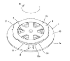
図1は、この発明の実施の形態1に係るディスククランパ100を取り付けたディスク装置を示す概略図である。ディスク装置は、情報記録媒体であるディスク6を載置するターンテーブル41と、このターンテーブル41を回転させるスピンドルモータ42と、ディスク6に対して情報の書き込み、読み出し又はその両方を行うピックアップ43とを備えている。ディスククランパ100は、ターンテーブル41との間でディスク6を挟み込んで保持するものである。
【0011】
図2(a)は、ディスククランパ100の平面図である。図2(b)は、図2(a)の線分A−Aにおける断面図であり、図2(c)は、ディスククランパ100の下面図である。図2(a)〜(c)に示すように、ディスククランパ100は、ディスク6の表面に当接するディスク接触面1aを有するクランパ本体1と、このクランパ本体1に取り付けられた蓋体2とを有している。クランパ本体1と蓋体2との間には、環状の吸着部材3が保持されている。
【0012】
図3(a)は、クランパ本体1の平面図である。図3(b)は、図3(a)の線分B−Bにおける断面図であり、図3(c)は、クランパ本体1の下面図である。図4は、クランパ本体1の斜視図である。図3(a)〜(c)に示すように、クランパ本体1は、上述したディスク接触面1aが形成された環状の基部10を有している。ディスク接触面1aは、基部10の下面に、外周に沿って一定の幅に形成された平坦面である。基部10の内周縁部には、上方、すなわちディスク接触面1a側と反対の側に突出する筒状の周壁12が一体に形成されている。周壁12の外周面及び内周面は、いずれも、ディスク接触面1aに対して直交する共通の軸線を中心とした円筒面となっている。以下の説明では、この軸線の方向を「軸方向」とする。
【0013】
周壁12の外周面には、3つの係合爪13が外側に突出するように形成されている。3つの係合爪13は、周壁12の周方向に等間隔に配置されており、いずれも、周壁12の軸方向よりも周方向に長く形成されている。各係合爪13は、周壁12の上端部、すなわち周壁12の軸方向において基部10側と反対側の端部に形成されている。各係合爪13の下面、すなわち基部10側の端面(水平係合面と言う。)13aは、ディスク接触面1aと平行に形成されている。各係合爪13の水平係合面13aの縁部から上方に延びた外周端面13bは、円筒面の一部をなしている。さらに外周端面13bの上端に連続して、基部10に近づくにつれて周壁12からの突出量が大きくなるよう傾斜した傾斜面13cが形成されている。
【0014】
周壁12の内側には、吸着部材3を保持するための環状の保持部18が形成されている。この保持部18の上面には、3つの弧形状部19が形成されている。これら3つの弧形状部19は、周壁12の周方向に等間隔に配置されている。各弧形状部19は、周壁12の内周面に沿って円弧状に延びており、その両端において周壁12の内周面に固定されている。
【0015】
図4に示すように、基部10には、弾性変形可能な3つの係止爪(弾性部材)14が形成されている。3つの係止爪14は、基部10の周方向に等間隔に配置されている。各係止爪14は、基部10の半径方向に長い略長方形状に形成され、基部10の外周側の1辺を残し、3辺がスリット16により囲まれたものである。すなわち、各係止爪14は、基部10の内周側の端部が最も大きく変位するよう弾性変形可能に構成されている。各係止爪14の内周側の端部には、上方に突出した突起14aが形成されている。基部10の周方向における突起14aの両端には、それぞれ傾斜面14bが形成されている。なお、基部10には、3つの開口部17が形成されているが、この開口部17は、金型を用いてクランパ本体1を樹脂により一体成形する際にアンダーカットが生じないようにするためのものである。
【0016】
図5(a)は、吸着部材3の平面図である。図5(b)は、図5(a)の線分C−Cにおける断面図である。吸着部材3は、マグネット又は磁性体(いわゆる吸着板金)により構成された環状の部材である。この吸着部材3は、クランパ本体1の保持部18(図4)上に載置され、弧形状部19(図4)により囲まれるようにして保持される。
【0017】
図6(a)は、蓋体2の平面図である。図6(b)は、図6(a)の線分D−Dにおける断面図であり、図6(c)は、蓋体2の下面図である。図7は、蓋体2を下方から見た斜視図である。図6(a)〜(c)に示すように、蓋体2は、環状部20を有しており、この環状部20の外周面には、その周方向において等間隔に6つの凸部21が形成されている。環状部20の内側には、下方、すなわちクランパ本体1(図4)側に突出する軸状の突起26を備えた中央支持部25が形成されている。中央支持部25と環状部20とは、開口20aにおいて放射状に形成された6本のアーム部27によって連結されている。中央支持部25は、クランパ本体1の保持部18(図4)上に保持された吸着部材3に当接する抑え面25aを有している。突起26は、ターンテーブル41の回転中心に形成された穴41a(図1)に挿入されるものである。
【0018】
図7に示すように、環状部20の内周縁部には、下方に突出する円筒状の周壁22が一体に形成されている。周壁22の外周面及び内周面は、いずれも、突起26の中心軸線を中心とした円筒面をなしている。周壁22の内周面には、3つの係合爪23が内側に突出するように形成されている。3つの係合爪23は、周壁22の下端部、すなわち周壁22の軸方向において環状部20側と反対側の端部に形成されており、周壁22の周方向に等間隔に配置されている。各係合爪23は、周壁22の軸方向よりも周方向に長く形成されており、その内周端面23bは、クランパ本体1の周壁12(図4)の外周面にほぼ沿う形状の円筒面の一部をなしている。係合爪23の環状部20側の端面(水平結合面と言う。)23aは、ディスク接触面1aに対して平行に形成されている。なお、上述したクランパ本体1の係合爪13の外周端面13b(図4)は、蓋体2の周壁22の内周面にほぼ沿う形状の円筒面の一部をなしている。
【0019】
周壁22の下端面22aには、3つの溝24が形成されている。3つの溝24は、周壁22の周方向に沿って等間隔に、且つクランパ本体1の3つの係止爪14の突起14a(図4)に対向可能な位置に形成されている。各溝24は、周壁22の周方向における両端が傾斜面24aとなっており、底に近づくほど溝幅(周壁22の周方向における寸法)が狭くなるように形成されている。
【0020】
次に、ディスククランパ100の組立方法について説明する。図8〜図10は、実施の形態1におけるディスククランパ100の組立方法を説明するための斜視図である。ディスククランパ100を組み立てる際には、まず、図8に示すように、吸着部材3をクランパ本体1の周壁12内に挿入し、保持部18上に載置する。次に、クランパ本体1の係合爪13及び蓋体2の係合爪23の周方向位置を互いに異ならせた状態で、クランパ本体1の周壁12の外側に蓋体2の周壁22を軸方向に嵌合させる。このとき、蓋体2の周壁22の下端面22aが、クランパ本体1の基部10の上面(ディスク接触面1aと反対側の面)に当接し、同時に、クランパ本体1の係止爪14を押圧して弾性変形させ、図9及び図11(a)の左側部分に示す状態となる。また、図11(a)の右側部分に拡大して示すように、クランパ本体1の係合爪13の外周端面13bが蓋体2の周壁22の内周面に当接し、又は、図11(b)に拡大して示すように、蓋体2の係合爪23の内周端面23bがクランパ本体1の周壁12の外周面に当接する。これにより、クランパ本体1と蓋体2とが相対回転可能に係合した状態となる。
【0021】
次に、蓋体2を、図9に矢印Rで示す方向又は反対方向に回転させる。蓋体2の溝24にクランパ本体1の係止爪14が係合するまで蓋体2を回転させると、図10及び図12に示す状態となる。このとき、図12に拡大して示すように、クランパ本体1の係合爪13の水平係合面13aと蓋体2の係合爪23の水平係合面23aとが軸方向に当接する。すなわち、クランパ本体1と蓋体2とは、係止爪14と溝24との係合により周方向に係止され、さらに係合爪13,23の係合により軸方向に互いに固定される。このようにして、クランパ本体1と蓋体2とは、吸着部材3を間に保持した状態で一体化し、ディスククランパ100の組立が完了する。
【0022】
なお、上述したディスククランパ100の組立においては、クランパ本体1と蓋体2と一体化する際、ディスククランパ100を保持するためのディスククランパ保持部材5(図1)をクランパ本体1と蓋体2とで挟み込むようにする。
【0023】
ディスククランパ100を分解する際には、図10に示した状態から、蓋体2を回転させる方向に一定以上の力を加える。蓋体2の溝24の傾斜面24a(図7)と係止爪14の傾斜面14b(図4)との摺動により、係止爪14が弾性変形して蓋体2の溝24から外れ、これにより蓋体2の回転が可能になる。蓋体2を回転させると、クランパ本体1の係合爪13と蓋体2の係合爪23との係合が外れ、蓋体2をクランパ本体1から軸方向に分離することが可能になる。蓋体2をクランパ本体1から分離したのち、クランパ本体1の周壁12の内側に収容された吸着部材3を取り出す。これにより、ディスククランパ100の分解が完了する。
【0024】
なお、ディスククランパ100の組立及び分解において、クランパ本体1に対して蓋体2を回転させる際には、作業者は、1本の指でクランパ本体1の基部10のディスク接触面1aを押さえ、別の指を蓋体2の外周縁に形成された凸部21に掛けて回転方向の力を作用させることができる。指と凸部21との間の係合(摩擦)により力を加えることができるため、指が滑って一体化に手間取るようなことが無くなり、組立作業を短時間で容易に行うことができる。
【0025】
次に、以上のように構成されたディスククランパ100のディスク装置内での作用について、図1を用いて説明する。ディスク6は、装置外部よりディスクローディング機構(図示せず)によりターンテーブル41上に搬入される。このとき、ディスククランパ保持部材5は、ディスククランパ100の蓋体2の環状部20に下方から当接し、ディスククランパ100を、搬入されるディスク6と干渉しない高さで保持している。ディスク6がターンテーブル41の上方に到達した時点で、ディスククランプ機構(図示せず)によりターンテーブル41が上昇し、又はディスククランパ保持部材5が下降する。これにより、ディスククランパ100のディスク接触面1aはディスク6の上面に当接し、蓋体2はディスククランパ保持部材5から上方に離間する。また、ディスククランパ100内の吸着部材3と、ターンテーブル41上の磁性体よりなる吸着板金(又はマグネット)との磁気的な吸引力により、ディスククランパ100は、ディスク6を間に挟んでターンテーブル41に吸着される。ディスククランパ100の突起26は、ターンテーブル41の回転中心に形成された穴41aに挿入される。ターンテーブル41に連結されたスピンドルモータ42が回転すると、ターンテーブル41、ディスククランパ100及びディスク6が一体的に回転する。この状態で、ピックアップ43により、ディスク6に対する信号の書き込み又は読み出しが行われる。なお、ディスククランパ100の回転中心は、突起26の中心軸線と一致しており、周壁12,22の中心軸線とも一致している。
【0026】
ディスク装置では、ターンテーブル41、スピンドルモータ42及びピックアップ43等は、耐振特性を向上させるためゴムダンパ等により弾性支持(フローティング支持)された記録再生ユニット4に取り付けられている。このディスク装置が、図1に矢印Zで示す方向に(すなわち、蓋体2側を下にして)落下した場合、ディスククランパ100には、ターンテーブル41を介して、記録再生ユニット4の重量の何十倍にも相当する衝撃が作用する。弾性支持されたターンテーブル41がZ方向に変位すると、ディスククランパ100もZ方向に変位し、クランパ本体1の基部10がディスククランパ保持部材5に当接する。このとき、クランパ本体1のZ方向への変位はディスククランパ保持部材5により阻止されるのに対し、蓋体2はターンテーブル41や吸着部材3を介してZ方向に尚も付勢されるため、クランパ本体1と蓋体2との間にはそれぞれを分離させようとする力が作用する。しかしながら、本実施の形態におけるディスククランパ100は、以下に説明するように、クランパ本体1と蓋体2との係合強度を十分高くすることができるため、クランパ本体1と蓋体2とが分離することはない。
【0027】
すなわち、上述したディスククランパ100の組立工程及び分解工程において、弾性変形する部分は係止爪14のみであり、大きな結合強度が要求されるクランパ本体1の係合爪13及び蓋体2の係合爪23は弾性変形しない。従って、係合爪13,23の係合面積(互いに当接し合う面積)を大きくし、係合爪13,23の係合を外れにくくすることができる。さらに、周壁12,22を弾性変形させる必要もないため、周壁12,22の肉厚を厚くし、かつ、スリット等を設けずに環状に連続した構造にすることができる。すなわち、周壁12,22が半径方向に殆ど変形しない構成とし、係合爪13,23の係合を一層外れにくくすることができる。このように、本実施の形態におけるディスククランパ100によれば、クランパ本体1と蓋体2との結合強度を極めて高くし、上述したように落下等による衝撃を受けた場合にクランパ本体1と蓋体2とが分離しないようにすることができる。
【0028】
なお、クランパ本体1と蓋体2の間に、クランパ本体1の係止爪14を弾性変形させるだけの回転力(トルク)が作用すると、クランパ本体1と蓋体2との相対回転により係合爪13,23の係合が外れ、クランパ本体1と蓋体2とが分離する。しかしながら、ディスク装置においては、クランパ本体1と蓋体2とは同一方向に回転するものであるため、クランパ本体1と蓋体2との間には、回転開始時又は停止時の急加速・急減速により生じるクランパ本体1及び蓋体2の回転力(回転軸回りの慣性モーメントと角加速度との積)の差に相当する回転力が作用するだけである。クランパ本体1及び蓋体2の慣性モーメントにはあまり差がないため、クランパ本体1の係止爪14を弾性変形させるだけの回転力は作用せず、従ってクランパ本体1と蓋体2とが分離することはない。
【0029】
以上説明したように、実施の形態1によれば、クランパ本体1の周壁12の外側に蓋体2の周壁22を嵌合可能とし、周壁12,22が周方向において所定の相対位置にあるときに係合爪13,23が軸方向に係合するよう構成したので、係合爪13,23の周方向位置を互いに異ならせた状態でクランパ本体1と蓋体2とを嵌合させ、ついで、クランパ本体1と蓋体2とを相対回転させて係合爪13,23を係合させることにより、クランパ本体1と蓋体2とを一体化することができる。係合爪13,23及び周壁12,22を弾性変形させる必要がないため、係合爪13,23の係合面積を大きくし、且つ、周壁12,22の肉厚を厚くすることが可能になり、クランパ本体1と蓋体2との結合強度を高めることができる。従って、ディスク装置の落下等による衝撃力を受けた場合でも、クランパ本体1と蓋体2とが分離することがない。
【0030】
さらに、ディスククランパ100の組立及び分解の際に係合爪13,23を弾性変形させないため、ディスククランパ100の組立及び分解を繰り返し行っても係合爪13,23の結合強度が低下することがなく、また、部品の破損も生じない。
【0031】
さらに、クランパ本体1の係止爪14と蓋体2の溝24との係合により、周壁12,22の相対回転を係止するようにしたので、周壁12,22に対して、係止爪14を弾性変形させるだけの回転力が作用しない限り、クランパ本体1と蓋体2とが分離されることは無い。従って、通常のディスク装置の使用状態において、クランパ本体1と蓋体2とが一体化した状態を維持することができる。
【0032】
また、係止爪14がクランパ本体1の基部10に形成されているため、周壁12,22の肉厚を厚くし、且つ、スリット等を設けずに環状に連続した構成にすることができる。すなわち、周壁12,22が殆ど弾性変形しないようにすることができ、その結果、クランパ本体1と蓋体2との結合強度をさらに高めることができる。
【0033】
また、蓋体2の外周縁に凸部21が形成されているため、クランパ本体1と蓋体2を一体化する際に、この凸部21に指を掛けて蓋体2を回転させることができる。すなわち、指を滑らせることなく、容易に組立作業を行うことができる。
【0034】
さらに、クランパ本体1及び蓋体2の係合爪13,23が周壁12,22の周方向に等間隔に配置されているので、クランパ本体1と蓋体2との係合を確実にすることができる。
【0035】
実施の形態2.
図13は、この発明の実施の形態2に係るディスククランパのクランパ本体1を示す斜視図である。実施の形態2に係るディスククランパでは、クランパ本体1の周壁12において、係合爪13の周方向における一方の端部から基部10に向けて延びた突出部7が設けられている。この突出部7は、蓋体2の係合爪23(図7)に周方向に当接するストッパ(規制手段)として作用する。その他の構成は、実施の形態1と同様である。
【0036】
クランパ本体1と蓋体2とを一体化する際には、クランパ本体1に対し、図13中矢印Rで示す方向に蓋体2(図7)を回転させ、蓋体2の係合爪23(図7)とクランパ本体1の係合爪13とを軸方向に係合させる。このとき、蓋体2の係合爪23が、クランパ本体1の係合爪13の一端に設けられた突出部7に当接し、蓋体2をこれ以上回転させることはできない。なお、実施の形態1と同様、クランパ本体1の係合爪13と蓋体2の係合爪23(図7)とが係合した状態で、クランパ本体1の係止爪14が、蓋体2の周壁22に形成された溝24(図7)に係合する。
【0037】
このように構成されているため、実施の形態2に係るディスククランパ100によれば、クランパ本体1と蓋体2とを一体化する際に、作業者は、蓋体2を一方向(図13に矢印Rで示す方向)に回転させることだけを意識すれば良い。すなわち、蓋体2を必要以上に回転させてしまい、係合爪13,23の係合が不十分になることを防止できる。
【0038】
なお、この実施の形態2では、係合爪13の一端部に連続して突出部7を形成したが、蓋体2の必要以上の回転を防止できる位置であれば、係合爪13から離れた位置に突出部7を設けてもよい。
【0039】
図14は、実施の形態2の変形例を示す斜視図である。この変形例では、蓋体2の周壁22における係合爪23の一端部から環状部20に向けて延びた突出部8が設けられている。この突出部8が、クランパ本体1の係合爪13に当接するストッパ(規制手段)として作用する。その他の構成は、実施の形態1と同様である。
【0040】
クランパ本体1と蓋体2とを一体化する際には、クランパ本体1(図4)に対し、図14中矢印Rで示す方向に蓋体2を回転させ、蓋体2の係合爪23とクランパ本体1の係合爪13(図4)とを係合させる。このとき、蓋体2の係合爪23の突出部8が、クランパ本体1の係合爪13に当接し、蓋体2をこれ以上回転させることはできない。従って、実施の形態2と同様、蓋体2を必要以上に回転させてしまい、係合爪13,23の係合が不十分になることを防止できる。
【0041】
この変形例では、係合爪23の一端部に連続して突出部8を形成したが、蓋体2の必要以上の回転を防止できる位置であれば、係合爪23から離れた位置に突出部8を設けてもよい。また、クランパ本体1及び蓋体2の両方に、それぞれ突出部7,8を設けることも可能である。
【0042】
なお、上記の各実施の形態では、クランパ本体1の周壁12の外側に蓋体2の周壁22が位置するようにしたが、逆に、クランパ本体1の周壁12の内側に蓋体2の周壁22が位置するようにしてもよい。この場合には、蓋体2の周壁22の内側に、吸着部材3が保持される。
【0043】
また、上記の各実施の形態では、ディスククランパ100の組立に際し、クランパ本体1を固定し、このクランパ本体1に対して蓋体2を回転させると説明したが、蓋体2を固定してクランパ本体1を回転させるようにしてもよい。さらに、クランパ本体1及び蓋体2の係合爪13,23は、それぞれ3つずつ設けられているが、個数はいくつであってもよい。
【0044】
さらに、上記の各実施の形態では、蓋体2の周壁22の下端面22aに溝24を形成し、クランパ本体1の基部10に係止爪14を形成したが、クランパ本体1の周壁12の端面に溝を形成し、蓋体2の環状部20に係止爪を形成してもよい。また、上記の各実施の形態では、蓋体2の外縁部に凸部21を形成するようにしたが、凸部21の代わりに凹部を設けてもよい。
【0045】
上述した実施の形態の説明では、「上」、「下」、「上端」、「上面」、「下端」、「下面」などの言葉を用いているが、これらは説明の便宜のためのものであって、完成された装置あるいは使用状態における装置の向きを表すものではない。例えば、説明中の「上端」が下向き、あるいは横向きになるように装置を構成することも可能である。
【0046】
【発明の効果】
以上のように、この発明によれば、クランパ本体の第1の周壁及び蓋体の第2の周壁を、一方の外側又は内側に他方が嵌合するよう構成し、これらが周方向において所定の相対位置にあるときに第1及び第2の係合爪が軸方向に係合するよう構成したので、第1及び第2の係合爪の周方向位置を互いに異ならせた状態で第1及び第2の周壁を互いに嵌合させ、第1及び第2の周壁を相対回転させて第1及び第2の係合爪を互いに係合させることにより、クランパ本体と蓋体とを一体化することができる。第1及び第2の係合爪を弾性変形させる必要がないため、第1及び第2の係合爪の係合面積を大きくして両者の係合を外れにくくすることが可能になる。また、第1及び第2の周壁の肉厚を厚くして変形を抑制することも可能になる。従って、クランパ本体と蓋体との結合強度を高め、ディスク装置の落下等による衝撃力を受けた場合のクランパ本体と蓋体との分離を防止することができる。
【図面の簡単な説明】
【図1】この発明の実施の形態1に係るディスククランパのディスク装置内での使用状態を示す断面図である。
【図2】この発明の実施の形態1に係るディスククランパの平面図(a)、そのA−A断面図(b)及び下面図(c)である。
【図3】この発明の実施の形態1に係るクランパ本体の平面図(a)、そのB−B断面図(b)及び下面図(c)である。
【図4】この発明の実施の形態1に係るクランパ本体の斜視図である。
【図5】この発明の実施の形態1に係る吸着部材の平面図(a)及びそのC−C断面図(b)である。
【図6】この発明の実施の形態1に係る蓋体の平面図(a)、そのD−D断面図(b)及び下面図(c)である。
【図7】この発明の実施の形態1に係る蓋体の斜視図である。
【図8】この発明の実施の形態1に係るディスククランパの分解斜視図である。
【図9】この発明の実施の形態1に係るディスククランパが一体化する途中の状態を示す斜視図である。
【図10】この発明の実施の形態1に係るディスククランパが一体化した状態を示す斜視図である。
【図11】この発明の実施の形態1に係るディスククランパの断面構造を拡大して示す断面図である。
【図12】この発明の実施の形態1に係るディスククランパにおける各係合爪の作用を説明するための断面図である。
【図13】この発明の実施の形態2に係るクランパ本体の斜視図である。
【図14】この発明の実施の形態2の変形例に係る蓋体の斜視図である。
【符号の説明】
1 クランパ本体、10 環状部、12 周壁、13 係合爪、14 係止爪、2 蓋体、20 環状部、21 凸部、22 周壁、23 係合爪、24 溝、3 吸着部材、4 記録再生ユニット、41 ターンテーブル、42 スピンドルモータ、43 ピックアップ、5 ディスククランパ保持部材、6 ディスク、7,8 ストッパ、100 ディスクククランパ[0001]
TECHNICAL FIELD OF THE INVENTION
The present invention relates to a disc clamper for holding a disc such as a compact disc between a turntable and rotating the disc and a method of assembling the disc clamper.
[0002]
[Prior art]
The disk clamper has a built-in magnet or the like for attracting a magnetic material or the like on the turntable in order to hold the disk between the turntable and the disk. Therefore, the disc clamper has a structure for holding a magnet or the like between the clamper body and the lid (for example, see Patent Document 1).
[0003]
[Patent Document 1]
JP-A-10-308047 (page 3-4, FIG. 1)
[0004]
[Problems to be solved by the invention]
In a conventional disk clamper, a tubular member (lid tube) provided on a lid is engaged with a cylindrical member (holding tube) provided on a clamper body. A claw that can be elastically deformed in the radial direction is integrally formed on the cylindrical wall of the lid cylinder. The holding cylinder is provided with an engagement hole that engages with the tip of the claw. When assembling the disc clamper, the lid cylinder is pushed in the axial direction inside the holding cylinder. At this time, after the claws of the holding cylinder are once elastically deformed inward, they are engaged with the engagement holes of the holding cylinder, and the clamper body and the lid are integrated by these engagements.
[0005]
In recent years, due to the demand for thinner disk devices, the length of the nail is often set to about 3 to 4 mm. If the length of the nail is so short, a large stress is generated at the base of the nail when the nail is elastically deformed. Therefore, in order to suppress the stress generated at the base of the nail to be equal to or less than the allowable stress of the constituent material (resin), the thickness of the nail is reduced or the amount of elastic deformation of the nail is reduced (that is, the engagement between the nail and the engagement hole). To make it shallower).
[0006]
However, if the thickness of the pawl is reduced or the engagement between the pawl and the engagement hole is made shallow, sufficient coupling strength between the clamper main body and the lid cannot be obtained. Therefore, when an impact force is applied to the clamper body and the lid in a direction to separate them from each other, for example, when the disk device is dropped, the claws are broken or the claws are disengaged from the engagement holes. May fall off from the turntable.
[0007]
Also, the disc clamper is required to have the same performance even after repeated assembly and disassembly, but when disassembling the disc clamper, the nail may be excessively deformed and the nail may be damaged from the base There is also.
[0008]
SUMMARY OF THE INVENTION The present invention has been made to solve the above-described problems, and enhances the bonding strength between a clamper main body and a lid so that the clamper main body and the lid can be separated from each other even when subjected to an impact due to a drop or the like. It is an object of the present invention to obtain a disk clamper having no disk and an assembling method thereof.
[0009]
[Means for Solving the Problems]
A disk clamper according to the present invention includes a base having a contact surface that contacts a disk, a first peripheral wall provided on a side of the base opposite to the contact surface, and a first peripheral wall. The lid includes a lid having a second peripheral wall attached thereto, and an adsorbing member held inside the first or second peripheral wall and made of a magnet or a magnetic material. One of the first and second peripheral walls has a peripheral surface that forms a substantially cylindrical surface, and the other peripheral wall hasOppositeBy doing so, it fits outside or inside the one peripheral wall. The first and second peripheral walls are engaged with each other in a direction of a central axis of the peripheral surface when the second peripheral wall is at a predetermined relative position to the first peripheral wall in a peripheral direction of the peripheral surface. The first and second engaging members are respectively provided.The first engagement member is formed so as to protrude from the first peripheral wall toward the second peripheral wall, and the second engagement member is formed from the second peripheral wall toward the first peripheral wall. The projection is formed.
[0010]
BEST MODE FOR CARRYING OUT THE INVENTION
Hereinafter, the present invention will be specifically described with reference to the drawings showing the embodiments.
FIG. 1 is a schematic diagram showing a disk device to which a
[0011]
FIG. 2A is a plan view of the
[0012]
FIG. 3A is a plan view of the clamper
[0013]
Three engaging
[0014]
An annular holding
[0015]
As shown in FIG. 4, three elastically deformable engaging claws (elastic members) 14 are formed on the
[0016]
FIG. 5A is a plan view of the
[0017]
FIG. 6A is a plan view of the
[0018]
As shown in FIG. 7, a cylindrical
[0019]
Three
[0020]
Next, a method of assembling the
[0021]
Next, the
[0022]
In the assembly of the
[0023]
When disassembling the
[0024]
In the assembly and disassembly of the
[0025]
Next, the operation of the
[0026]
In the disk device, the turntable 41, the
[0027]
That is, in the assembling process and the disassembling process of the
[0028]
When a rotational force (torque) enough to elastically deform the locking
[0029]
As described above, according to the first embodiment, the
[0030]
Furthermore, since the engaging
[0031]
Further, since the relative rotation of the
[0032]
In addition, since the locking
[0033]
Further, since the
[0034]
Further, since the engaging
[0035]
FIG. 13 is a perspective view showing the clamper
[0036]
When the clamper
[0037]
According to the
[0038]
In the second embodiment, the protruding
[0039]
FIG. 14 is a perspective view showing a modification of the second embodiment. In this modification, a protruding
[0040]
When the clamper
[0041]
In this modified example, the protruding
[0042]
In each of the above embodiments, the
[0043]
Further, in each of the above-described embodiments, when assembling the
[0044]
Further, in each of the above embodiments, the
[0045]
In the above description of the embodiment, words such as “upper”, “lower”, “upper end”, “upper surface”, “lower end”, “lower surface” are used, but these are for convenience of explanation. It does not indicate the orientation of the completed device or the device in use. For example, the device can be configured such that the “upper end” in the description is directed downward or sideways.
[0046]
【The invention's effect】
As described above, according to the present invention, the first peripheral wall of the clamper main body and the second peripheral wall of the lid are configured so that one of them is fitted to the outside or the inside of the other, and these are arranged at predetermined positions in the circumferential direction. Since the first and second engaging claws are configured to engage in the axial direction when they are at the relative position, the first and second engaging claws are arranged so that the circumferential positions of the first and second engaging claws are different from each other. The clamper body and the lid are integrated by engaging the second peripheral walls with each other and rotating the first and second peripheral walls relative to each other to engage the first and second engaging claws with each other. Can be. Since there is no need to elastically deform the first and second engaging claws, it is possible to increase the engaging area of the first and second engaging claws and make it difficult for them to be disengaged. In addition, it is possible to suppress deformation by increasing the thickness of the first and second peripheral walls. Accordingly, the coupling strength between the clamper main body and the lid body can be increased, and separation of the clamper main body and the lid body when receiving an impact force due to dropping of the disk device or the like can be prevented.
[Brief description of the drawings]
FIG. 1 is a sectional view showing a use state of a disk clamper according to
FIGS. 2A and 2B are a plan view, a cross-sectional view taken along line AA of FIG. 2, and a bottom view of the disk clamper according to the first embodiment of the present invention.
FIGS. 3A and 3B are a plan view, a BB sectional view, and a bottom view, respectively, of the clamper main body according to
FIG. 4 is a perspective view of a clamper main body according to
5A is a plan view of the suction member according to the first embodiment of the present invention, and FIG.
FIG. 6 is a plan view (a), a sectional view taken along line DD (b), and a bottom view (c) of the lid according to
FIG. 7 is a perspective view of the lid according to the first embodiment of the present invention.
FIG. 8 is an exploded perspective view of the disc clamper according to the first embodiment of the present invention.
FIG. 9 is a perspective view showing a state where the disc clamper according to the first embodiment of the present invention is being integrated.
FIG. 10 is a perspective view showing a state where the disc clamper according to the first embodiment of the present invention is integrated;
FIG. 11 is an enlarged sectional view showing a sectional structure of the disk clamper according to the first embodiment of the present invention.
FIG. 12 is a cross-sectional view for explaining the operation of each engaging claw in the disc clamper according to the first embodiment of the present invention.
FIG. 13 is a perspective view of a clamper main body according to
FIG. 14 is a perspective view of a lid according to a modification of the second embodiment of the present invention.
[Explanation of symbols]
Claims (10)
前記第1の周壁の外側又は内側に取り付けられる第2の周壁を有する蓋体と、
前記第1又は第2の周壁の内側に保持され、マグネット又は磁性体よりなる吸着部材と を備え、
前記第1及び第2の周壁のうち、一方の周壁が、略円筒面をなす周面を有し、他方の周壁が、前記周面に対向することにより前記一方の周壁の外側又は内側に嵌合し、
前記第1及び第2の周壁は、前記第2の周壁が前記第1の周壁に対し前記周面の周方向において所定の相対位置にあるときに前記周面の中心軸線の方向に互いに係合する第1及び第2の係合部材をそれぞれ有し、
前記第1の係合部材は、前記第1の周壁から前記第2の周壁に向けて突出形成され、前記第2の係合部材は、前記第2の周壁から前記第1の周壁に向けて突出形成されていること
を特徴とするディスククランパ。A clamper body having a base having a contact surface that contacts the disc, and a first peripheral wall provided on the opposite side of the base from the contact surface;
A lid having a second peripheral wall attached to the outside or the inside of the first peripheral wall,
An adsorbing member held inside the first or second peripheral wall and made of a magnet or a magnetic material;
One of the first and second peripheral walls has a peripheral surface that forms a substantially cylindrical surface, and the other peripheral wall is fitted to the outside or the inside of the one peripheral wall by facing the peripheral surface. And
The first and second peripheral walls are engaged with each other in a direction of a central axis of the peripheral surface when the second peripheral wall is at a predetermined relative position to the first peripheral wall in a peripheral direction of the peripheral surface. the first and second engagement members which possess respectively,
The first engagement member is formed so as to protrude from the first peripheral wall toward the second peripheral wall, and the second engagement member is formed from the second peripheral wall toward the first peripheral wall. A disk clamper formed to project .
前記第2の周壁の端面又は前記第1の周壁の端面に形成された溝と、
前記クランパ本体又は前記蓋体に、前記溝が形成された前記端面に対向するように設けられ、前記溝に係合可能な弾性部材と、
を有することを特徴とする請求項2に記載のディスククランパ。The locking means,
A groove formed on an end surface of the second peripheral wall or an end surface of the first peripheral wall;
An elastic member provided on the clamper main body or the lid so as to face the end face in which the groove is formed, and capable of engaging with the groove;
3. The disk clamper according to claim 2, comprising:
前記第1又は第2の周壁の内側に、マグネット又は磁性体よりなる吸着部材を装着する工程と、
前記第1及び第2の係合部材の前記周方向の位置を互いに異ならせた状態で、前記第1及び第2の周壁を互いに嵌合させる工程と、
前記第1及び第2の周壁を前記周方向に相対回転させて前記第1及び第2の係合部材を互いに係合させる工程と
を含むことを特徴とするディスククランパの組立方法。A clamper body having a base having a contact surface for contacting the disc, a first peripheral wall provided on the opposite side of the base from the contact surface, and a second clamp attached to the outside or the inside of the first peripheral wall Wherein one peripheral wall has a peripheral surface that forms a substantially cylindrical surface, and the other peripheral wall is fitted on the outside or inside of the one peripheral wall by facing the peripheral surface. When the first and second peripheral walls are at a predetermined relative position in the circumferential direction of the peripheral surface with respect to the first peripheral wall, the first and second peripheral walls are oriented in the direction of the center axis of the peripheral surface. possess respectively the first and second engagement member engaged with each other, the first engagement member, the first formed projecting toward the second wall from the peripheral wall, the second engagement if members are those which are formed to protrude toward the first wall from the second wall A step of preparing,
Mounting a suction member made of a magnet or a magnetic material inside the first or second peripheral wall;
Fitting the first and second peripheral walls to each other in a state where the positions of the first and second engagement members in the circumferential direction are different from each other;
Rotating the first and second peripheral walls in the circumferential direction to engage the first and second engaging members with each other.
Priority Applications (4)
| Application Number | Priority Date | Filing Date | Title |
|---|---|---|---|
| JP2002354917A JP3547429B2 (en) | 2002-12-06 | 2002-12-06 | Disc clamper and method of assembling the same |
| PCT/JP2003/011779 WO2004053863A1 (en) | 2002-12-06 | 2003-09-16 | Disk clamper and method of assembling the same |
| US10/512,481 US7263704B2 (en) | 2002-12-06 | 2003-09-16 | Disk clamper and method of assembling the same |
| TW092127139A TWI231473B (en) | 2002-12-06 | 2003-10-01 | Disk clamper and method for assembling same |
Applications Claiming Priority (1)
| Application Number | Priority Date | Filing Date | Title |
|---|---|---|---|
| JP2002354917A JP3547429B2 (en) | 2002-12-06 | 2002-12-06 | Disc clamper and method of assembling the same |
Publications (3)
| Publication Number | Publication Date |
|---|---|
| JP2004185774A JP2004185774A (en) | 2004-07-02 |
| JP3547429B2 true JP3547429B2 (en) | 2004-07-28 |
| JP2004185774A5 JP2004185774A5 (en) | 2005-02-24 |
Family
ID=32500771
Family Applications (1)
| Application Number | Title | Priority Date | Filing Date |
|---|---|---|---|
| JP2002354917A Expired - Fee Related JP3547429B2 (en) | 2002-12-06 | 2002-12-06 | Disc clamper and method of assembling the same |
Country Status (4)
| Country | Link |
|---|---|
| US (1) | US7263704B2 (en) |
| JP (1) | JP3547429B2 (en) |
| TW (1) | TWI231473B (en) |
| WO (1) | WO2004053863A1 (en) |
Families Citing this family (10)
| Publication number | Priority date | Publication date | Assignee | Title |
|---|---|---|---|---|
| TWI222262B (en) * | 2003-07-24 | 2004-10-11 | Delta Electronics Inc | Spindle motor centering device |
| CN100550151C (en) * | 2004-03-26 | 2009-10-14 | 皇家飞利浦电子股份有限公司 | The equipment of information medium is used for centering on turntable |
| JP2007066429A (en) * | 2005-08-31 | 2007-03-15 | Orion Denki Kk | Clamper of recording/reproducing apparatus, and recording/reproducing apparatus with the clamper |
| WO2008078282A2 (en) * | 2006-12-22 | 2008-07-03 | Koninklijke Philips Electronics N.V. | Drive unit for a data medium |
| JP2010225252A (en) * | 2009-03-25 | 2010-10-07 | Sony Corp | Disc loading mechanism, disk drive apparatus |
| KR101120292B1 (en) * | 2009-06-08 | 2012-03-06 | 니혼 덴산 가부시키가이샤 | Turntable and method for manufacturing the same |
| KR101083124B1 (en) | 2009-09-17 | 2011-11-11 | 엘지이노텍 주식회사 | Spindle motor |
| JP5532858B2 (en) * | 2009-11-26 | 2014-06-25 | 船井電機株式会社 | Disc clamper |
| KR20120082199A (en) | 2011-01-13 | 2012-07-23 | 엘지이노텍 주식회사 | Turn table for spindle motor and spindle motor having the same |
| JP5423730B2 (en) | 2011-06-16 | 2014-02-19 | 船井電機株式会社 | Optical disk device |
Family Cites Families (13)
| Publication number | Priority date | Publication date | Assignee | Title |
|---|---|---|---|---|
| KR900004661B1 (en) * | 1986-01-20 | 1990-07-02 | 가부시키가이샤 도시바 | Optical information processing apparatus |
| JPH0399729U (en) | 1990-01-31 | 1991-10-18 | ||
| JPH08195010A (en) * | 1995-01-13 | 1996-07-30 | Matsushita Electric Ind Co Ltd | Disk centering device |
| KR100224829B1 (en) * | 1996-07-10 | 1999-10-15 | 윤종용 | Optical disc drive |
| JPH10283703A (en) * | 1997-04-02 | 1998-10-23 | Mitsumi Electric Co Ltd | Disk clamper and disk drive having the same disk clamper |
| JPH10308047A (en) | 1997-05-02 | 1998-11-17 | Tokyo Pijiyon Kk | Disk clamper |
| CN1229242A (en) * | 1998-03-18 | 1999-09-22 | 株式会社三协精机制作所 | Gripper mechanism for recording disk |
| JP3059729U (en) * | 1998-12-09 | 1999-07-13 | 船井電機株式会社 | Disk-shaped recording disk chucking device |
| JP2001143345A (en) * | 1999-11-10 | 2001-05-25 | Matsushita Electric Ind Co Ltd | Disk clamper |
| JP3578334B2 (en) * | 2000-10-12 | 2004-10-20 | 船井電機株式会社 | Disc player chucking device |
| TW505296U (en) * | 2001-10-12 | 2002-10-01 | Lite On It Corp | Reed type clamping device |
| TW591625B (en) * | 2002-01-15 | 2004-06-11 | Benq Corp | Apparatus for reducing tray-in noise |
| TWI222262B (en) * | 2003-07-24 | 2004-10-11 | Delta Electronics Inc | Spindle motor centering device |
-
2002
- 2002-12-06 JP JP2002354917A patent/JP3547429B2/en not_active Expired - Fee Related
-
2003
- 2003-09-16 US US10/512,481 patent/US7263704B2/en not_active Expired - Lifetime
- 2003-09-16 WO PCT/JP2003/011779 patent/WO2004053863A1/en active Application Filing
- 2003-10-01 TW TW092127139A patent/TWI231473B/en not_active IP Right Cessation
Also Published As
| Publication number | Publication date |
|---|---|
| JP2004185774A (en) | 2004-07-02 |
| US20050223401A1 (en) | 2005-10-06 |
| TW200410205A (en) | 2004-06-16 |
| TWI231473B (en) | 2005-04-21 |
| US7263704B2 (en) | 2007-08-28 |
| WO2004053863A1 (en) | 2004-06-24 |
Similar Documents
| Publication | Publication Date | Title |
|---|---|---|
| TW468154B (en) | A device for retaining a disc | |
| JP3547429B2 (en) | Disc clamper and method of assembling the same | |
| US6959443B2 (en) | Removable disk drive apparatus having large and small disk support lugs | |
| JPH03157859A (en) | Disk chucking mechanism | |
| US6567238B1 (en) | Disc clamp for a disc drive | |
| JP2006048821A (en) | Motor for recording disk driving and recording disk driver using the motor for recording disk driving | |
| EP1560212B1 (en) | Disk clamping apparatus and hard disk drive with the same | |
| JPH10106134A (en) | Disk drive device | |
| JP3008870B2 (en) | Turntable device for disk media | |
| JP5288421B2 (en) | Disc chucking device, motor and disc drive device equipped with the same | |
| JPH09106600A (en) | Disk chucking device for compact disk player | |
| JP2004213812A (en) | Disk chucking mechanism and motor with the same | |
| JP4097389B2 (en) | Disc alignment structure | |
| JP2780164B2 (en) | Turntable for information record carrier | |
| JP2002260313A (en) | Disk chucking device and motor equipped with the same | |
| JPH11213498A (en) | Disk chucking mechanism | |
| JP2001273695A (en) | Disk chucking mechanism and disk drive assembly having the same | |
| KR0140883B1 (en) | Center core of magnetic disk | |
| JP2000113545A (en) | Spindle motor | |
| JP2523684B2 (en) | Magnetic disk | |
| KR20020012975A (en) | The disc separation preventing apparatus for disk drive | |
| JP4062863B2 (en) | Disc chucking mechanism and recording / reproducing apparatus using the same | |
| JPH11162061A (en) | Disk device | |
| JPH064457Y2 (en) | Disk adapter | |
| JP3479207B2 (en) | Disk rotation drive |
Legal Events
| Date | Code | Title | Description |
|---|---|---|---|
| TRDD | Decision of grant or rejection written | ||
| A01 | Written decision to grant a patent or to grant a registration (utility model) |
Free format text: JAPANESE INTERMEDIATE CODE: A01 Effective date: 20040413 |
|
| A61 | First payment of annual fees (during grant procedure) |
Free format text: JAPANESE INTERMEDIATE CODE: A61 Effective date: 20040413 |
|
| R150 | Certificate of patent or registration of utility model |
Ref document number: 3547429 Country of ref document: JP Free format text: JAPANESE INTERMEDIATE CODE: R150 Free format text: JAPANESE INTERMEDIATE CODE: R150 |
|
| A975 | Report on accelerated examination |
Free format text: JAPANESE INTERMEDIATE CODE: A971005 Effective date: 20040405 |
|
| FPAY | Renewal fee payment (event date is renewal date of database) |
Free format text: PAYMENT UNTIL: 20080423 Year of fee payment: 4 |
|
| FPAY | Renewal fee payment (event date is renewal date of database) |
Free format text: PAYMENT UNTIL: 20090423 Year of fee payment: 5 |
|
| FPAY | Renewal fee payment (event date is renewal date of database) |
Free format text: PAYMENT UNTIL: 20100423 Year of fee payment: 6 |
|
| FPAY | Renewal fee payment (event date is renewal date of database) |
Free format text: PAYMENT UNTIL: 20100423 Year of fee payment: 6 |
|
| FPAY | Renewal fee payment (event date is renewal date of database) |
Free format text: PAYMENT UNTIL: 20110423 Year of fee payment: 7 |
|
| FPAY | Renewal fee payment (event date is renewal date of database) |
Free format text: PAYMENT UNTIL: 20120423 Year of fee payment: 8 |
|
| FPAY | Renewal fee payment (event date is renewal date of database) |
Free format text: PAYMENT UNTIL: 20120423 Year of fee payment: 8 |
|
| FPAY | Renewal fee payment (event date is renewal date of database) |
Free format text: PAYMENT UNTIL: 20130423 Year of fee payment: 9 |
|
| FPAY | Renewal fee payment (event date is renewal date of database) |
Free format text: PAYMENT UNTIL: 20130423 Year of fee payment: 9 |
|
| FPAY | Renewal fee payment (event date is renewal date of database) |
Free format text: PAYMENT UNTIL: 20140423 Year of fee payment: 10 |
|
| R250 | Receipt of annual fees |
Free format text: JAPANESE INTERMEDIATE CODE: R250 |
|
| R250 | Receipt of annual fees |
Free format text: JAPANESE INTERMEDIATE CODE: R250 |
|
| R250 | Receipt of annual fees |
Free format text: JAPANESE INTERMEDIATE CODE: R250 |
|
| R250 | Receipt of annual fees |
Free format text: JAPANESE INTERMEDIATE CODE: R250 |
|
| LAPS | Cancellation because of no payment of annual fees |