JP3545560B2 - Cabinet and cabinet mounting structure - Google Patents
Cabinet and cabinet mounting structure Download PDFInfo
- Publication number
- JP3545560B2 JP3545560B2 JP01736197A JP1736197A JP3545560B2 JP 3545560 B2 JP3545560 B2 JP 3545560B2 JP 01736197 A JP01736197 A JP 01736197A JP 1736197 A JP1736197 A JP 1736197A JP 3545560 B2 JP3545560 B2 JP 3545560B2
- Authority
- JP
- Japan
- Prior art keywords
- opening
- shell
- article
- cabinet
- screw
- Prior art date
- Legal status (The legal status is an assumption and is not a legal conclusion. Google has not performed a legal analysis and makes no representation as to the accuracy of the status listed.)
- Expired - Fee Related
Links
Images


Landscapes
- Assembled Shelves (AREA)
Description
【0001】
【発明の属する技術分野】
本発明は、例えば洗面台の近傍に設けられるキャビネット及び同キャビネットの取付構造に関する。
【0002】
【発明の目的】
本発明の1つの目的は、左右一側面が開口した補強箱と、この補強箱内に、物品出し入れ開口が補強箱の開口側を向くようにして収納固定された被殻体とを有するキャビネットにおいて、被殻体を補強箱に綺麗に取り付けることが出来る構造を有するキャビネットを提供することにある。
また、本発明の別の目的は、部屋の側壁に形成された開口に物品出し入れ開口を有する被殻体を有するキャビネットを、綺麗に取り付けることが出来る構造を提供することにある。
【0003】
【前記目的を達成するための手段】
本発明は前記目的を達成するために以下の如き手段を採用した。
請求項1の発明は、左右一側面が開口した補強箱と、この補強箱内に、物品出し入れ開口が補強箱の開口側を向くようにして収納固定された被殻体とを有するキャビネットにおいて、前記補強箱の前壁前面が装飾面となされ、この前壁の、補強箱の開口側端部に上下に渡る溝が形成され、この溝に被殻体の物品出し入れ開口縁部に形成された前側の折返片が嵌め入れられ、被殻体の物品出し入れ開口近くに取り付けられる被取付部材のために被殻体の前壁に形成された貫通孔を通じて、ねじが折返片を貫通するようにして前壁にねじ嵌められており、前記貫通孔が被取付部材によって閉塞されているものである。
請求項4の発明は、部屋の側壁に開口が形成され、この開口に、物品出し入れ開口を有する被殻体を有するキャビネットが、物品出し入れ開口を部屋の側壁の開口側に向けるようにして嵌め入れられ、前記被殻体の物品出し入れ開口縁部に形成された折返片が部屋の側壁の開口の内側面に対向するようになされ、被殻体の物品出し入れ開口近くに取り付けられる被取付部材のために被殻体に形成された貫通孔を通じて、ねじが折返片を通じて部屋の側壁の開口の縁部にねじ嵌められており、前記貫通孔が被取付部材によって閉塞されているものである。
【0004】
【発明の作用】
請求項1の発明は以下の如き作用をなすものである。
装飾面にねじが露出しないように、且つ、被殻体の前壁に貫通孔やそれを閉塞するキャップ等が見えないようにして、被殻体を補強箱に固定することが出来る。
請求項4の発明は以下の如き作用をなすものである。
被殻体の前壁に貫通孔やそれを閉塞するキャップ等が見えないようにして、被殻体を部屋の側壁に形成された開口に固定することが出来る。
【0005】
【発明の実施の形態】
以下に、3つの、本発明の実施の形態を図面を参照しつつ説明する。
なお、これらの説明において同一の部材は同一の符号で示す。
【0006】
[第1の、発明の実施の形態](図1〜図4参照)
なお、この説明において、前とは図1紙面表側を、後とは同裏をいい、左とは図1左側を、右とは同図右側をいう。
【0007】
洗面化粧台ユニット1は、洗面台2と、この洗面台2の後部上方に配された化粧キャビネット3と、前記洗面台2及び化粧キャビネット3の左側方に配された側部キャビネット4とを有している。
前記側部キャビネット4は、下側キャビネット5と上側キャビネット6とを有している。
【0008】
前記洗面台2は、上面開放のキャビネット本体9と、このキャビネット本体9の上部に設けられた、水槽10及びバックガ−ド11を有する天板12とを有している。
【0009】
前記化粧キャビネット3は、所要個の物品載置棚16(物品収納凹所の下部面)及び上部の照明器具収納凹所18を有する合成樹脂製本体15を有しており、この合成樹脂製本体15に、鏡20付きの扉21、照明器具(図示略)及び照明器具カバー22等を取り付けることによって構成されている。
化粧キャビネット3は、具体的にはバックガ−ド11の上に載せられて、部屋の側壁に固定されている。
【0010】
前記側部キャビネット4の上側キャビネット6は、洗面台2側(右側)に開口25を有する木製等の補強箱24と、この補強箱24内に、物品出し入れ開口29が補強箱24の開口25側(右側)を向くようにして収納固定された合成樹脂製・金属製の被殻体28とを有している。
【0011】
前記補強箱24の前壁31は、前面及び上下左右側面(後面を除く残りの面)が装飾面32aとなされた前側板32と、この前側板32が所要個のねじ34によって固定された後側板33とによって構成されている(図3参照)。なお、ねじ34は、後側板33の後面から前側板32にねじ嵌められており、装飾面32aにねじ34が露出しないようになされている。
【0012】
前記補強箱24の開口25側の全外側面(前壁31は、後側板33の右端部前面)に段落ち部37が形成されている。後側板33の右端部前面に形成された段落ち部37は、前側板32によって前から見えないようになり、請求の範囲でいうところの、前壁31の、開口25側端部に形成された上下に渡る溝を構成している。この説明から明らかなごとく、前側板32と後側板33を一体ものとした場合、前壁31の、開口25側端部に上下に渡る溝が形成されるものである。
【0013】
前記被殻体28は、所要個の物品載置棚40(物品収納凹所の下部面)を有すると共に、被殻体28の、物品出し入れ開口29側の全外周縁に左方向に向く折返片41が連設されている。前記被殻体28の前後の側壁42に(少なくとも1つの、具体的には2つの物品載置棚40のやや上部の前後の側壁42に)、相互に対向する貫通孔43が形成されている。
【0014】
前記被殻体28は、折返片41を段落ち部37に嵌めるかたちで被殻体28に嵌められている。そして、図3及び図4に示すごとく、上下の折返片41及び後側の折返片41は、それらに形成されたねじ挿通孔を通じてねじ34を補強箱24にねじ嵌めることによって固定され、前側の折返片41は、前壁42の貫通孔43を通じて、ねじ34を折返片41を貫通するようにして前壁31(後側板33及び前側板32)にねじ嵌めることによって、補強箱24に固定されている。
【0015】
前記相互に対向する前後の貫通孔43に金属製・合成樹脂製の物品落下防止桟45(請求の範囲でいう被取付部材)の前後端部が以下のようにして嵌め入れられている。即ち、まず、物品落下防止桟45の後端部を後側の貫通孔43に嵌め入れた後、物品落下防止桟45を撓ませて、物品落下防止桟45の前端部を前側の貫通孔43に嵌め入れる。そして、この状態で物品落下防止桟45からそれを撓ませる力を除けば、物品落下防止桟45は一直線となり、ほぼ補強箱24の前壁31及び後壁に当たった状態となり、物品落下防止桟45は貫通孔43から抜け出さない。
ここでご注目戴きたいのは、(1)前後側の貫通孔43が物品落下防止桟45によって閉塞されること、(2)前側の折返片41を止めるためねじ34を前側板32側からねじ嵌めるとすれば装飾面32aにねじ34の頭が露出することになり、更に、(3)後側板33に前側の折返片41をねじ34で固定した後では、後側板33に前側板32を固定するため後側板33の後方から前側板32にねじ34をねじ嵌めることが出来ず、他方、前側板32側からねじ34をねじ嵌めれば、装飾面32aにねじ34の頭が露出することになることである。
【0016】
[第2の、発明の実施の形態](図5参照)
なお、この説明において、前とは図5紙面表側を、後とは同裏側をいい、左とは図5左側を、右とは同図右側をいう。
【0017】
フック48(請求の範囲で云う被取付部材)にフック固定ねじ49が設けられ、このフック固定ねじ49が、前後側の貫通孔43を貫通して前壁31及び折返片41にねじ嵌められ、前後側の貫通孔43はフック48の基部で閉塞されている。
フック48にはコップの把手等が引っ掛けられる。
【0018】
[第3の、発明の実施の形態](図6〜図8参照)
なお、この説明において、前とは図6紙面表側を、後とは同裏をいい、左とは図6左側を、右とは同図右側をいう。
【0019】
部屋52の側壁53に開口54が形成され、この開口54に、物品出し入れ開口29を有する被殻体28を有するキャビネット56が、物品出し入れ開口29を開口54側に向けるようにして嵌め入れられ、前記被殻体28の、物品出し入れ開口29側の全外周縁に形成された折返片41が開口54の内側面54aに対向するようになされ、左右の貫通孔43(被殻体28の左右の側壁57に形成された貫通孔43)を通じて、ねじ34が、補強箱24の左右の側壁、被殻体28の折返片41を通じて側壁53の開口54の縁部にねじ嵌められている。
補強箱24は前方に開口25を有すると共に、前記補強箱24の開口25側の全外側面に折返片41が嵌まる段落ち部37が形成されている。なお、補強箱24はなくてもよい。
【0020】
【変形例等】
以下に変形例等について説明を加える。
(1)被取付部材は、物品落下防止桟45やフック48以外であってもよい。
(2)被取付部材を、被殻体28の上部又は下部に取り付けるようにしてもよい。
(3)第1、第2の、発明の実施の形態において、開口25及び物品出し入れ開口29を左側に向けるようにしてもよい。
(4)第3の、発明の実施の形態において、折返片41は、少なくとも被殻体28の、物品出し入れ開口29側の一側縁に設けられればよい。
(5)第1、第2の、発明の実施の形態において、前側の折返片41以外の折返片41はなくてもよい。
(6)第3の、発明の実施の形態における物品落下防止桟45に代えて、第2の、発明の実施の形態のフック48を取り付けるようにしてもよい。
【0021】
【発明の効果】
本発明は前記した如き構成によって以下の如き効果を奏するものである。
▲1▼請求項1〜3の発明によれば、装飾面にねじが露出しないように、且つ、被殻体の前壁に貫通孔やそれを閉塞するキャップ等が見えないようにして、被殻体を補強箱に固定することが出来る。
▲2▼請求項4〜6の発明によれば、被殻体の前壁に貫通孔やそれを閉塞するキャップ等が見えないようにして、被殻体を部屋の側壁に形成された開口に固定することが出来る。
【図面の簡単な説明】
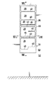
【図1】本発明の、第1の実施の形態を示す一部破砕の正面図である。
【図2】図1のII−II線断面図である。
【図3】図1のIII−III線に沿う中間省略の拡大断面図である。
【図4】図1のA部分の中間省略の拡大断面図である。
【図5】本発明の、第2の実施の形態を示す一部破砕の要部正面図である。
【図6】本発明の、第3の実施の形態を示す正面図である。
【図7】図6のVII−VII線に沿う中間省略の拡大断面図である。
【図8】図7のVIII−VIII線に沿う中間省略の拡大断面図である。
【符号の説明】
6 上側キャビネット
24 補強箱
25 開口
28 被殻体
29 物品出し入れ開口
31 前壁
32 前側板
32a 装飾面
33 後側板
34 ねじ
37 段落ち部
56 キャビネット[0001]
TECHNICAL FIELD OF THE INVENTION
The present invention relates to a cabinet provided near a wash basin, for example, and a mounting structure of the cabinet.
[0002]
[Object of the invention]
An object of the present invention is to provide a cabinet having a reinforcing box having one side open on the left and right sides, and a shell placed and fixed in the reinforcing box such that an article taking-out opening faces the opening side of the reinforcing box. It is another object of the present invention to provide a cabinet having a structure in which a shell can be neatly attached to a reinforcing box.
Another object of the present invention is to provide a structure capable of neatly mounting a cabinet having a shell having an article access opening in an opening formed in a side wall of a room.
[0003]
[Means for achieving the above object]
The present invention employs the following means to achieve the above object.
The invention according to claim 1 is a cabinet having a reinforcing box having one left and right side opening, and a shell body stored and fixed in the reinforcing box such that an article taking-out opening faces the opening side of the reinforcing box. The front surface of the front wall of the reinforcing box was a decorative surface, and a vertical groove was formed at the opening end of the front wall of the reinforcing box. The screw is passed through the turn-back piece through a through-hole formed in the front wall of the shell for the member to be attached to which the front turn piece is fitted and which is mounted near the article access opening of the shell. The through-hole is screwed to the front wall, and the through-hole is closed by the attached member.
According to a fourth aspect of the present invention, an opening is formed in a side wall of a room, and a cabinet having a shell having an article taking-out opening is fitted into the opening so that the article taking-out opening faces the opening side of the side wall of the room. A folded member formed at the edge of the article putting-in / out opening of the shell is opposed to the inner side surface of the opening in the side wall of the room, and is a member to be attached near the article putting-in / out opening of the shell. A screw is screwed into a rim of an opening of a side wall of a room through a folded piece through a through hole formed in the shell body, and the through hole is closed by a member to be mounted.
[0004]
Effect of the Invention
The invention of claim 1 has the following operation.
The shell can be fixed to the reinforcing box such that the screw is not exposed on the decorative surface and the through hole and the cap closing the hole are not visible on the front wall of the shell.
The invention of
The shell can be fixed to the opening formed in the side wall of the room so that the through-hole and the cap closing the hole are not visible on the front wall of the shell.
[0005]
BEST MODE FOR CARRYING OUT THE INVENTION
Hereinafter, three embodiments of the present invention will be described with reference to the drawings.
In these descriptions, the same members are denoted by the same reference numerals.
[0006]
[First Embodiment of the Invention] (see FIGS. 1 to 4)
In this description, "front" means the front side of FIG. 1, "back" means "back", "left" means the left side of FIG. 1, and "right" means the right side of FIG.
[0007]
The vanity unit 1 includes a
The
[0008]
The
[0009]
The
The
[0010]
The
[0011]
The
[0012]
A step-down
[0013]
The
[0014]
The
[0015]
The front and rear ends of a metal / synthetic resin article fall prevention bar 45 (attached member in the claims) are fitted into the front and rear through
Here, it should be noted that (1) the through
[0016]
[Second Embodiment of the Invention] (See FIG. 5)
In this description, “front” refers to the front side of the sheet of FIG. 5, “back” refers to the back side, “left” refers to the left side in FIG. 5, and “right” refers to the right side in FIG.
[0017]
A hook 48 (a member to be attached in the claims) is provided with a
A handle of a cup or the like is hooked on the
[0018]
[Third Embodiment of the Invention] (see FIGS. 6 to 8)
In this description, the front means the front side of the paper of FIG. 6, the rear means the back side, the left means the left side of FIG. 6, and the right means the right side of the figure.
[0019]
An
The reinforcing
[0020]
[Modifications, etc.]
A description will be given below of modified examples and the like.
(1) The attached member may be other than the article
(2) The mounting member may be mounted on the upper or lower part of the
(3) In the first and second embodiments of the invention, the
(4) In the third embodiment of the invention, the folded
(5) In the first and second embodiments of the present invention, the folded
(6) The
[0021]
【The invention's effect】
The present invention has the following effects by the configuration described above.
(1) According to the first to third aspects of the present invention, the screw is not exposed on the decorative surface, and the through-hole and the cap for closing the through-hole are not visible on the front wall of the shell. The shell can be fixed to the reinforcement box.
(2) According to the invention of
[Brief description of the drawings]
FIG. 1 is a partially fragmented front view showing a first embodiment of the present invention.
FIG. 2 is a sectional view taken along line II-II of FIG.
FIG. 3 is an enlarged cross-sectional view taken along the line III-III of FIG. 1 without an intermediate portion.
FIG. 4 is an enlarged sectional view of a portion A in FIG.
FIG. 5 is a front view of a main part of a partial crusher showing a second embodiment of the present invention.
FIG. 6 is a front view showing a third embodiment of the present invention.
FIG. 7 is an enlarged cross-sectional view taken along the line VII-VII of FIG.
8 is an enlarged cross-sectional view taken along the line VIII-VIII of FIG.
[Explanation of symbols]
6
Claims (6)
Priority Applications (1)
| Application Number | Priority Date | Filing Date | Title |
|---|---|---|---|
| JP01736197A JP3545560B2 (en) | 1997-01-13 | 1997-01-13 | Cabinet and cabinet mounting structure |
Applications Claiming Priority (1)
| Application Number | Priority Date | Filing Date | Title |
|---|---|---|---|
| JP01736197A JP3545560B2 (en) | 1997-01-13 | 1997-01-13 | Cabinet and cabinet mounting structure |
Publications (2)
| Publication Number | Publication Date |
|---|---|
| JPH10192070A JPH10192070A (en) | 1998-07-28 |
| JP3545560B2 true JP3545560B2 (en) | 2004-07-21 |
Family
ID=11941906
Family Applications (1)
| Application Number | Title | Priority Date | Filing Date |
|---|---|---|---|
| JP01736197A Expired - Fee Related JP3545560B2 (en) | 1997-01-13 | 1997-01-13 | Cabinet and cabinet mounting structure |
Country Status (1)
| Country | Link |
|---|---|
| JP (1) | JP3545560B2 (en) |
-
1997
- 1997-01-13 JP JP01736197A patent/JP3545560B2/en not_active Expired - Fee Related
Also Published As
| Publication number | Publication date |
|---|---|
| JPH10192070A (en) | 1998-07-28 |
Similar Documents
| Publication | Publication Date | Title |
|---|---|---|
| USD888354S1 (en) | Laundry washing module | |
| US8506025B2 (en) | Supporter and pedestal and washing/drying machine having the same | |
| USD503536S1 (en) | Upright luggage having side access compartment | |
| USD444333S1 (en) | Front opening corner soap dish | |
| USD455501S1 (en) | Storage shed with multiple access doors | |
| USD422807S (en) | Storage cabinet | |
| JP4729995B2 (en) | sink | |
| USD418038S (en) | Cabinet door restraint | |
| JP3545560B2 (en) | Cabinet and cabinet mounting structure | |
| USD411392S (en) | Computer cabinet | |
| JP2913579B2 (en) | Tray mounting structure | |
| USD358052S (en) | Bathroom convenience cabinet | |
| USD456951S1 (en) | Nail dryer with storage compartment | |
| JP3634092B2 (en) | Vanity unit | |
| USD412061S (en) | Portable double-sided flip-bins storage unit | |
| KR101396079B1 (en) | a closet | |
| JPH0355316Y2 (en) | ||
| USD471425S1 (en) | Door hinge on a modular storage shed | |
| USD407482S (en) | Bottom cover for a ceiling fan | |
| USD415273S (en) | Combined cabinet with glove box and container for housing medical waste | |
| KR930006524Y1 (en) | Front bumper box for jeep | |
| JP2023005704A (en) | kitchen cabinet | |
| JPS5818755Y2 (en) | Structure of shelves in makeup cabinet | |
| JP2896852B2 (en) | Partition panel | |
| KR200343451Y1 (en) | Bathroom Cabinet |
Legal Events
| Date | Code | Title | Description |
|---|---|---|---|
| TRDD | Decision of grant or rejection written | ||
| A01 | Written decision to grant a patent or to grant a registration (utility model) |
Free format text: JAPANESE INTERMEDIATE CODE: A01 Effective date: 20040406 |
|
| A61 | First payment of annual fees (during grant procedure) |
Free format text: JAPANESE INTERMEDIATE CODE: A61 Effective date: 20040408 |
|
| R150 | Certificate of patent or registration of utility model |
Free format text: JAPANESE INTERMEDIATE CODE: R150 |
|
| FPAY | Renewal fee payment (event date is renewal date of database) |
Free format text: PAYMENT UNTIL: 20080416 Year of fee payment: 4 |
|
| FPAY | Renewal fee payment (event date is renewal date of database) |
Free format text: PAYMENT UNTIL: 20090416 Year of fee payment: 5 |
|
| FPAY | Renewal fee payment (event date is renewal date of database) |
Free format text: PAYMENT UNTIL: 20100416 Year of fee payment: 6 |
|
| FPAY | Renewal fee payment (event date is renewal date of database) |
Free format text: PAYMENT UNTIL: 20110416 Year of fee payment: 7 |
|
| FPAY | Renewal fee payment (event date is renewal date of database) |
Free format text: PAYMENT UNTIL: 20120416 Year of fee payment: 8 |
|
| FPAY | Renewal fee payment (event date is renewal date of database) |
Free format text: PAYMENT UNTIL: 20130416 Year of fee payment: 9 |
|
| LAPS | Cancellation because of no payment of annual fees |