JP3540552B2 - Vacuum cleaner suction tool - Google Patents
Vacuum cleaner suction tool Download PDFInfo
- Publication number
- JP3540552B2 JP3540552B2 JP18800497A JP18800497A JP3540552B2 JP 3540552 B2 JP3540552 B2 JP 3540552B2 JP 18800497 A JP18800497 A JP 18800497A JP 18800497 A JP18800497 A JP 18800497A JP 3540552 B2 JP3540552 B2 JP 3540552B2
- Authority
- JP
- Japan
- Prior art keywords
- suction tool
- suction
- vacuum cleaner
- main body
- carpet
- Prior art date
- Legal status (The legal status is an assumption and is not a legal conclusion. Google has not performed a legal analysis and makes no representation as to the accuracy of the status listed.)
- Expired - Lifetime
Links
Images
Landscapes
- Nozzles For Electric Vacuum Cleaners (AREA)
Description
【0001】
【発明の属する技術分野】
本発明は、電気掃除機の吸込具に係り、特に床面に風を吹き付ける開口を備えた電気掃除機の吸込具に関するものである。
【0002】
【従来の技術】
従来より、ごみ吸い込み性能を上げる目的で、吸込具における吸込風流を床面に衝突させ、ごみを掻き上げる方法がある。
【0003】
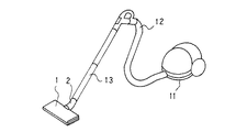
図17、図18、図19、図20は、例えば特開昭54−158066号公報に開示されいる従来の電気掃除機用吸込具の例を示す図であり、図17は断面図、図18は正面図、図19は底面図、図20は斜視図である。図において、1は吸込具本体で、掃除機本体11とホース12、パイプ13を介して接続される連通管2が止め具3より回転自在に取り付けられている。4は吸込具本体1前方に設けたそり部であり、その中央には吸込口5を有し、吸込口5の左右には長溝の吸込通路6が設けられている。7は吸込口5及び吸込通路6の前方に連通されたスリット状の通風路であり、吸込具本体1の長手方向に数個独立して設けられている。また、通風路7は吸込口5の中央部長手方向両端に至るに従いその孔面積は大きくなっている。
【0004】
8は吸込具本体1の外周に設けられた緩衝材のバンパー、9は吸込具本体1の底面に左右に設けたローラー、10は吸込口4の後方に設けた植毛であり、掃除の時、吸込具本体1の裏面が床面と接触してキズつけることを防いでいる。
【0005】
上記構成により床面の掃除を行うと、そり部4下面及びスリット状の通風路7から流入した空気流が合流し床面の深部などへ衝突する。この気流によりごみを掻き上げて吸引するので、掃除能力を向上させることができる。
【0006】
【発明が解決しようとする課題】
上記のように構成された従来の電気掃除機用吸込具においては、吸込具本体1に入り込む吸引風を吸込具本体1に形成した通風路7により床面に衝突させて床面にあるごみをその衝突風にて掻き上げて吸塵性能を上げようとしている。床面がじゅうたんである場合は、じゅうたんの毛の内部に入り込んだ塵埃を掻き出すためにスリット状の通風路7をじゅうたんの毛に近づける必要がある。
【0007】
しかしながら、従来のようにケース部材である吸込具本体1に通風路7を形成したのでは吸込具本体1が剛体であるため、じゅうたんに通風路7の出口を近づけたとき、じゅうたんの種類によっては毛の長さが異なるので、通気孔7の開口が塞がれてしまう場合があり、十分な掻き上げ性能が得られないという問題点がある。
【0008】
この発明は、上述のような課題を解決するためになされたもので、じゅうたん内部の塵埃を衝突風の生じる通風路7にて掻き出す効果を向上させるために通風路7をじゅうたんに近づけることができ、かつ種々の毛の長さのじゅうたんに対しても通風路を塞ぐことなく常に安定した掻き上げ性能を得るようにするものである。
【0009】
【課題を解決するための手段】
この発明に係る電気掃除機用吸込具は、連通管を介して掃除機本体と接続する吸込具本体と、前記吸込具本体の底面前方に形成され前記連通管と連通する吸込口と、前記吸込具本体の外周に設けられた軟質材よりなるバンパーと、軟質材で形成され前記バンパーと一体的に設けられ前記バンパーより清掃面側に垂下し、上部に空気取り入れ口を設け、清掃面側に噴出口を設けた通風路とを備え、前記通風路のバンパー側の壁面に、清掃面と接触するような位置に垂下したスカート部を設け、吸込具本体を前進・後進させたとき、清掃面の抵抗により前記スカート部が吸込具本体の進行方向に対し反対方向に曲げられ、該スカート部と一体的に形成された通風路も同じ方向に曲げられることにより、該スカート部の動きに対応して噴出口が変動するものである。
【0010】
また、前記スカート部と前記噴出口との間にリブを設けたものである。
【0012】
【発明の実施の形態】
実施の形態1.
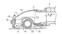
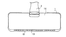
図1はこの発明の実施形態1に係る電気掃除機用吸込具の内部構造を示す側方からの断面図、図2は上面図、図3は正面図、図4は下面図である。図中、従来例と同一または相当する部分には同一符号を付し説明は省略する。なお、吸込具本体1の略中央部には従来例同様、掃除機本体11とホース12、パイプ13を介して接続される連通管2が設置されているものとする。
【0013】
図において、14は吸込具本体1の上ケース、15は下ケースである。16は吸込具本体1内部の長手方向中央部に設けた仕切壁であり、前方が吸込室17となっている。下ケース15の吸込室17には吸込口4が形成されている。18は吸込具本体1の外周部に配置されたバンパーであり、壁、家具などにぶつかった際にキズをつけないように軟質材料により形成されている。19は軟質材料で形成された通風路であり、バンパー18と一体的に形成されている。19aは通風路19の吸込具本体1上面側に形成された空気取入口、19bは清掃面側に設けた噴出口である。20は起毛布を外周に接着した起毛布ローラーであり、吸込口5の後方に配設されている。起毛布ローラー20ーの軸受け部には回転を規制するトルクリミッターが内蔵されており板床の時には吸込具本体1の移動速度よりもゆっくり回転して拭き機能が得られるようになっている。
【0014】
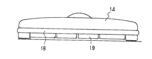
通風路19は、図1、図2、図3に示すように複数個設けられており、吸込具本体1の前側に床面に対して垂直に形成されている。通風路19の断面形状は円、四角、長穴などのいかなる形状でもよい。また、各通風路19の通風路はそれぞれ独立した形状でも複数個が合体した形状になっていてもよい。
【0015】
掃除機本体の吸引動作にともない吸込具本体1の吸込口5より床面のごみとともに周辺空気を吸込む。その時に吸込具本体1前面にある通風路19からも周辺空気は吸引され、この吸引風は通風路19に導かれて床面に衝突し、その衝突風によりごみが掻き上げられて連通管2へ流れ込む。
【0016】
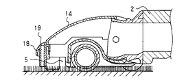
しかしながら、ごみ掻き上げ機能の性能を十分に引き出すためには、通風路19の床面側の口部をごみのある床面部に近づける必要がある。そこで、図5、図6、図7を用いて説明する。図5は吸込具本体1をじゅうたん上に載置した状態を示す図、図6は吸込具本体1を前進させた時の通風路19の状態を示す図、図7は吸込具本体1を後進させた時の通風路19の状態を示す図である。
【0017】
図に示すように、実施の形態1によれば、通風路19は軟質材料で形成されているので、吸込具本体1を前進・後進させたとき、じゅうたんの抵抗により通風路19は吸込具本体1の進行方向に対し反対方向に曲げられる。この変形により通風路19の床面側の口部はじゅうたんの毛の上に出るため、吸込具本体1を前後に動作していれば、通風路19の開口を塞ぐことは防止できる。したがって、通風路19を通過した吸引風は常にじゅうたんの毛の中にあるごみに衝突して掻き上げることができる。
【0018】
実施の形態2.
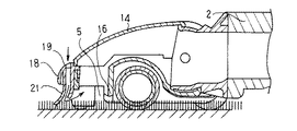
図8はこの発明の実施形態2に係る電気掃除機用吸込具を示す断面図、図9は正面図、図10は底面図である。図において、実施の形態1と同一または相当する構成には同一符号を付し説明は省略する。21は通風路19のバンパー18側壁面を床面と略接触するように垂下したスカート部である。
【0019】
スカート部21は板状の床面上では床面と吸込具本体1の隙間をある一定間隔にして吸込口5の負圧を保つように構成している。また、じゅうたん上ではじゅうたんの毛の中に入り込むように構成されている。
【0020】
図11は吸込具本体1をじゅうたん上に載置した状態を示す図、図12は吸込具本体1の前進時の状態を示す図、図13は吸込具本体1の後進時の状態を示す図である。実施形態2によれば、じゅうたん上で吸込具本体1を前進・後進させるとスカート部21がじゅうたんの抵抗により吸込具本体1の進行方向に対して反対方向に曲げられるため、スカート部21と一体的に形成された通風路19も同じ方向に変形される。つまり、スカート部21により吸込具本体1の進行方向が検知されて通風路19が変形する。これにより、通風路19の床面側口部は塞がれることなく、通風路19の衝突風による掻き上げ性能を維持することができる。
【0021】
実施の形態3.
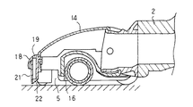
図14はこの発明の実施の形態3に係る電気掃除機用吸込具の内部構造を示す図、図15は吸込具本体をじゅうたん上で前進させた状態を示す図、図16は下面図である。図において、実施の形態1、2と同一の構成には同一符号を付し説明は省略する。22はスカート部21と通風路19をつなぐ補強リブである。
【0022】
実施形態3によれば、補強リブ22により、じゅうたん上の吸込具本体1の前進・後進動作によって生じるスカート部21の変形を確実に通風路19へつたえることができる。
【0023】
【発明の効果】
以上述べたように、床面への衝突風を得る通風路において、床面側の開口部がじゅうたんに埋まるような状態になってもじゅうたんの抵抗により通風路が変形して床面側の口は常にじゅうたん上にでていて風路が確保されるため通風路の通過風による床面への掻き上げ性能を維持することができる。
【0024】
また、垂下されたスカート部により吸込具の進行方向が検知され、通風路が変形されるため、じゅうたんに床面側の口を塞がれることを防ぐことができる。
【0025】
また、スカート部と通風路との連動性を補強リブにより向上させるので、確実に通風路の口の風路を確保できる。
【図面の簡単な説明】
【図1】本発明の実施の形態1に係る電気掃除機用吸込具の内部構造を示す断面図である。
【図2】実施の形態1に係る電気掃除機用吸込具の上面図である。
【図3】実施の形態1に係る電気掃除機用吸込具の正面図である。
【図4】実施の形態1に係る電気掃除機用吸込具の底面図である。
【図5】実施の形態1に係る電気掃除機用吸込具のじゅうたん上での状態を示す図である。
【図6】実施の形態1に係る電気掃除機用吸込具のじゅうたん上での前進状態を示す図である。
【図7】実施の形態1に係る電気掃除機用吸込具のじゅうたん上での後進状態を示す図である。
【図8】本発明の実施の形態2に係る電気掃除機用吸込具の内部構造を示す断面図である。
【図9】実施の形態2に係る電気掃除機用吸込具の正面図である。
【図10】実施の形態2に係る電気掃除機用吸込具の底面図である。
【図11】実施の形態2に係る電気掃除機用吸込具のじゅうたん上での状態を示す図である。
【図12】実施の形態2に係る電気掃除機用吸込具のじゅうたん上での前進状態を示す図である。
【図13】実施の形態2に係る電気掃除機用吸込具のじゅうたん上での後進状態を示す図である。
【図14】本発明の実施の形態3に係る電気掃除機用吸込具の内部構造を示す断面図である。
【図15】実施の形態3に係る電気掃除機用吸込具のじゅうたん上での前進状態を示す図である。
【図16】実施の形態3に係る電気掃除機用吸込具の底面図である。
【図17】従来の電気掃除機用吸込具の内部構造を示す側方からの断面図である。
【図18】従来の電気掃除機用吸込具の正面図である。
【図19】従来の電気掃除機用吸込具の底面図である。
【図20】従来の電気掃除機用吸込具の斜視図である。
【符号の説明】
1 吸込具本体、2 連通管、5 吸込口、6 吸込通路、7 通風路、
8 バンパー、11 掃除機本体、12 ホース、13 パイプ、
18 バンパー、19 通風路、21 スカート部、22 補強リブ。[0001]
TECHNICAL FIELD OF THE INVENTION
The present invention relates to a suction device of a vacuum cleaner, and more particularly to a suction device of a vacuum cleaner having an opening for blowing air to a floor.
[0002]
[Prior art]
BACKGROUND ART Conventionally, there is a method in which a suction airflow from a suction tool collides with a floor surface to scrape up dust in order to improve dust suction performance.
[0003]
FIGS. 17, 18, 19, and 20 are views showing examples of a conventional vacuum cleaner suction tool disclosed in, for example, Japanese Patent Application Laid-Open No. 54-158066. FIG. 17 is a cross-sectional view. 19 is a front view, FIG. 19 is a bottom view, and FIG. 20 is a perspective view. In the drawing,
[0004]
[0005]
When the floor surface is cleaned by the above configuration, the airflows flowing from the lower surface of the
[0006]
[Problems to be solved by the invention]
In the conventional suction device for a vacuum cleaner configured as described above, the suction air entering the suction device
[0007]
However, when the
[0008]
The present invention has been made to solve the above-described problems, and can improve the effect of scraping dust inside the carpet in the
[0009]
[Means for Solving the Problems]
For an electric vacuum cleaner suction tool according to the present invention, a suction tool main body connected to the cleaner body through the communicating pipe, and the suction port communicating with said communicating pipe is formed on the bottom front of the suction tool body, wherein A bumper made of a soft material provided on the outer periphery of the suction tool main body, and formed of a soft material and provided integrally with the bumper, hanging down from the bumper to a cleaning surface side, providing an air intake port at an upper portion, and providing a cleaning surface side And a ventilation passage provided with a discharge port, a skirt portion hanging down at a position in contact with a cleaning surface is provided on a wall surface of the ventilation passage on the bumper side, and cleaning is performed when the suction tool body is moved forward and backward. The skirt portion is bent in the opposite direction to the direction of travel of the suction tool main body due to surface resistance, and the ventilation passage formed integrally with the skirt portion is also bent in the same direction, thereby responding to the movement of the skirt portion. And the spout fluctuates Is shall.
[0010]
Further, a rib is provided between the skirt portion and the ejection port.
[0012]
BEST MODE FOR CARRYING OUT THE INVENTION
1 is a side sectional view showing the internal structure of a vacuum cleaner suction tool according to
[0013]
In the drawing, 14 is an upper case of the suction tool
[0014]
As shown in FIGS. 1, 2 and 3, a plurality of
[0015]
With the suction operation of the vacuum cleaner body, the surrounding air is sucked together with the dust on the floor from the
[0016]
However, in order to sufficiently bring out the performance of the dust scraping function, it is necessary to bring the opening on the floor side of the
[0017]
As shown in the drawing, according to the first embodiment, since the
[0018]
8 is a sectional view showing a vacuum cleaner suction tool according to
[0019]
The
[0020]
FIG. 11 is a view showing a state where the suction tool
[0021]
FIG. 14 is a view showing the internal structure of a vacuum cleaner suction tool according to
[0022]
According to the third embodiment, the deformation of the
[0023]
【The invention's effect】
As described above, even if the floor-side opening becomes buried in the carpet, the ventilation path is deformed by the resistance of the carpet and the floor-side opening is formed in the ventilation path that obtains the impinging wind on the floor. Is always on the carpet and the air passage is secured, so that the performance of scraping the floor surface by the wind passing through the air passage can be maintained.
[0024]
Further, since the traveling direction of the suction tool is detected by the suspended skirt portion, and the ventilation path is deformed, it is possible to prevent the floor-side mouth from being closed by the carpet.
[0025]
In addition, since the interlocking property between the skirt portion and the ventilation path is improved by the reinforcing rib, the air path at the mouth of the ventilation path can be reliably secured.
[Brief description of the drawings]
FIG. 1 is a cross-sectional view showing an internal structure of a vacuum cleaner suction tool according to
FIG. 2 is a top view of the suction tool for a vacuum cleaner according to the first embodiment.
FIG. 3 is a front view of the suction tool for a vacuum cleaner according to
4 is a bottom view of the vacuum cleaner suction tool according to
FIG. 5 is a diagram showing a state of the suction device for a vacuum cleaner according to
FIG. 6 is a diagram showing a state in which the suction device for a vacuum cleaner according to
FIG. 7 is a diagram showing a state in which the suction device for a vacuum cleaner according to the first embodiment moves backward on a carpet.
FIG. 8 is a cross-sectional view showing an internal structure of a vacuum cleaner suction tool according to
FIG. 9 is a front view of the vacuum cleaner suction tool according to the second embodiment.
FIG. 10 is a bottom view of the vacuum cleaner suction tool according to the second embodiment.
FIG. 11 is a diagram showing a state on a carpet of a vacuum cleaner suction tool according to
FIG. 12 is a diagram showing a state in which the suction device for a vacuum cleaner according to
FIG. 13 is a diagram showing a state in which the suction device for a vacuum cleaner according to the second embodiment moves backward on a carpet.
FIG. 14 is a cross-sectional view showing an internal structure of a vacuum cleaner suction tool according to
FIG. 15 is a diagram showing a state in which the suction device for a vacuum cleaner according to
FIG. 16 is a bottom view of the suction tool for a vacuum cleaner according to
FIG. 17 is a side sectional view showing the internal structure of a conventional vacuum cleaner suction tool.
FIG. 18 is a front view of a conventional vacuum cleaner suction tool.
FIG. 19 is a bottom view of a conventional suction tool for a vacuum cleaner.
FIG. 20 is a perspective view of a conventional vacuum cleaner suction tool.
[Explanation of symbols]
1 suction tool body, 2 communication pipe, 5 suction port, 6 suction passage, 7 ventilation path,
8 bumper, 11 cleaner body, 12 hose, 13 pipe,
18 bumper, 19 ventilation path, 21 skirt part, 22 reinforcing rib.
Claims (2)
Priority Applications (1)
| Application Number | Priority Date | Filing Date | Title |
|---|---|---|---|
| JP18800497A JP3540552B2 (en) | 1997-07-14 | 1997-07-14 | Vacuum cleaner suction tool |
Applications Claiming Priority (1)
| Application Number | Priority Date | Filing Date | Title |
|---|---|---|---|
| JP18800497A JP3540552B2 (en) | 1997-07-14 | 1997-07-14 | Vacuum cleaner suction tool |
Publications (2)
| Publication Number | Publication Date |
|---|---|
| JPH1128178A JPH1128178A (en) | 1999-02-02 |
| JP3540552B2 true JP3540552B2 (en) | 2004-07-07 |
Family
ID=16215967
Family Applications (1)
| Application Number | Title | Priority Date | Filing Date |
|---|---|---|---|
| JP18800497A Expired - Lifetime JP3540552B2 (en) | 1997-07-14 | 1997-07-14 | Vacuum cleaner suction tool |
Country Status (1)
| Country | Link |
|---|---|
| JP (1) | JP3540552B2 (en) |
Families Citing this family (6)
| Publication number | Priority date | Publication date | Assignee | Title |
|---|---|---|---|---|
| US11992172B2 (en) | 2018-10-19 | 2024-05-28 | Sharkninja Operating Llc | Agitator for a surface treatment apparatus and a surface treatment apparatus having the same |
| US10702108B2 (en) | 2015-09-28 | 2020-07-07 | Sharkninja Operating Llc | Surface cleaning head for vacuum cleaner |
| US11647881B2 (en) | 2015-10-21 | 2023-05-16 | Sharkninja Operating Llc | Cleaning apparatus with combing unit for removing debris from cleaning roller |
| CA3002859C (en) * | 2015-10-21 | 2024-02-13 | Sharkninja Operating Llc | Surface cleaning head with leading roller |
| US11202542B2 (en) | 2017-05-25 | 2021-12-21 | Sharkninja Operating Llc | Robotic cleaner with dual cleaning rollers |
| CN112888352B (en) | 2018-10-19 | 2023-06-23 | 尚科宁家运营有限公司 | Agitator for surface treatment equipment and surface treatment equipment having the agitator |
-
1997
- 1997-07-14 JP JP18800497A patent/JP3540552B2/en not_active Expired - Lifetime
Also Published As
| Publication number | Publication date |
|---|---|
| JPH1128178A (en) | 1999-02-02 |
Similar Documents
| Publication | Publication Date | Title |
|---|---|---|
| US7134164B2 (en) | Vacuum cleaner nozzle assembly having edge-cleaning ducts | |
| KR101457162B1 (en) | Vacuum cleaner | |
| JP3540552B2 (en) | Vacuum cleaner suction tool | |
| JP4051777B2 (en) | Vacuum cleaner suction tool and vacuum cleaner | |
| TW201936106A (en) | A cleaner head | |
| JP2005028183A (en) | Vacuum cleaner suction tool | |
| JP3863096B2 (en) | Suction port and vacuum cleaner | |
| JP4958168B2 (en) | Suction port body for vacuum cleaner | |
| JP4331666B2 (en) | Suction port body of electric vacuum cleaner and electric vacuum cleaner provided with the same | |
| KR20040105163A (en) | Suction nozzle structure for cleaner | |
| JPH11187988A (en) | Airflow circulating type cleaner | |
| JP4347538B2 (en) | Vacuum cleaner inlet | |
| JPH1156710A (en) | Suction aperture assembly for vacuum cleaner | |
| JPH10192200A (en) | Electric vacuum cleaner | |
| JPH025408B2 (en) | ||
| JPH0210971Y2 (en) | ||
| JP3167978B2 (en) | Vacuum cleaner suction nozzle | |
| JP3819641B2 (en) | Suction port and vacuum cleaner | |
| JP3765028B2 (en) | Vacuum cleaner suction tool | |
| KR100667861B1 (en) | Vacuum cleaner | |
| JPH10108810A (en) | Electric vacuum cleaner | |
| JPH11113816A (en) | Vacuum cleaner suction tool | |
| JPH1170063A (en) | Suction device for floor | |
| JP3482137B2 (en) | Suction port body and vacuum cleaner | |
| JP3026837U (en) | Internal pressure type dust collector |
Legal Events
| Date | Code | Title | Description |
|---|---|---|---|
| TRDD | Decision of grant or rejection written | ||
| A01 | Written decision to grant a patent or to grant a registration (utility model) |
Free format text: JAPANESE INTERMEDIATE CODE: A01 Effective date: 20040323 |
|
| A61 | First payment of annual fees (during grant procedure) |
Free format text: JAPANESE INTERMEDIATE CODE: A61 Effective date: 20040325 |
|
| R150 | Certificate of patent or registration of utility model |
Free format text: JAPANESE INTERMEDIATE CODE: R150 |
|
| FPAY | Renewal fee payment (event date is renewal date of database) |
Free format text: PAYMENT UNTIL: 20080402 Year of fee payment: 4 |
|
| FPAY | Renewal fee payment (event date is renewal date of database) |
Free format text: PAYMENT UNTIL: 20090402 Year of fee payment: 5 |
|
| FPAY | Renewal fee payment (event date is renewal date of database) |
Free format text: PAYMENT UNTIL: 20100402 Year of fee payment: 6 |
|
| FPAY | Renewal fee payment (event date is renewal date of database) |
Free format text: PAYMENT UNTIL: 20100402 Year of fee payment: 6 |
|
| FPAY | Renewal fee payment (event date is renewal date of database) |
Free format text: PAYMENT UNTIL: 20110402 Year of fee payment: 7 |
|
| FPAY | Renewal fee payment (event date is renewal date of database) |
Free format text: PAYMENT UNTIL: 20120402 Year of fee payment: 8 |
|
| FPAY | Renewal fee payment (event date is renewal date of database) |
Free format text: PAYMENT UNTIL: 20120402 Year of fee payment: 8 |
|
| FPAY | Renewal fee payment (event date is renewal date of database) |
Free format text: PAYMENT UNTIL: 20130402 Year of fee payment: 9 |
|
| FPAY | Renewal fee payment (event date is renewal date of database) |
Free format text: PAYMENT UNTIL: 20130402 Year of fee payment: 9 |
|
| FPAY | Renewal fee payment (event date is renewal date of database) |
Free format text: PAYMENT UNTIL: 20140402 Year of fee payment: 10 |
|
| R250 | Receipt of annual fees |
Free format text: JAPANESE INTERMEDIATE CODE: R250 |
|
| R250 | Receipt of annual fees |
Free format text: JAPANESE INTERMEDIATE CODE: R250 |
|
| EXPY | Cancellation because of completion of term |
