JP3539779B2 - Signal band control device - Google Patents
Signal band control device Download PDFInfo
- Publication number
- JP3539779B2 JP3539779B2 JP00462895A JP462895A JP3539779B2 JP 3539779 B2 JP3539779 B2 JP 3539779B2 JP 00462895 A JP00462895 A JP 00462895A JP 462895 A JP462895 A JP 462895A JP 3539779 B2 JP3539779 B2 JP 3539779B2
- Authority
- JP
- Japan
- Prior art keywords
- signal
- signal band
- switching
- subscriber
- switching device
- Prior art date
- Legal status (The legal status is an assumption and is not a legal conclusion. Google has not performed a legal analysis and makes no representation as to the accuracy of the status listed.)
- Expired - Lifetime
Links
Images


Landscapes
- Telephonic Communication Services (AREA)
Description
【0001】
【産業上の利用分野】
本発明は、旧交換装置から新交換装置への回線移行時において信号帯域を制御する信号帯域制御装置に関するものである。
【0002】
【従来の技術】
機能アップした新しい交換装置に、今まで使用していた交換装置を取り替えることがしばしば行なわれ、この際には、回線を収容する交換装置を旧交換装置から新交換装置に移行する。
【0003】
このように旧交換装置から新交換装置に回線を移行する場合には、収容端末及び交換装置間に介在している布線装置(MDF)内において回線が一時的に2重布線状態となり、回線が一時的に旧交換装置及び新交換装置の両方向に存在してしまう。このような状態において、端末側からの発呼を新交換装置が検出することを停止させるために、また、新交換装置の装置工事の影響を端末側の回線で保証するために、2重布線状態にする前に、新交換装置の回線の切断が必要となっている。
【0004】
このような新交換装置の回線の切断を、従来では、布線装置内の導通状態切替回路を物理的に非導通状態へ切替操作することによって行なっていた。
【0005】
そして、その後、2重布線状態へ移行し、導通状態切替回路によって、旧交換装置の回線の切断、新交換装置の回線の接続を行なって新交換装置への回線の移行を行なっていた。
【0006】
【発明が解決しようとする課題】
しかしながら、導通状態切替回路の物理的な切替えを人手によって行なっており、作業が非常に煩雑になっており、作業効率が低いものであった。導通状態切替回路の物理的な切替えは、実際上、局番(1万回線)単位に繰返すために、かかる作業面での課題は大きい。
【0007】
また、布線装置内の導通状態切替回路を物理的に非導通状態へ切替えたときや、導通状態へ切替えたときには、新交換装置において、切替に係る全ての回線(1万回線)に対して、ノイズが発呼信号として一斉に検出されることがあり、また、端末側の回線に対しては布線装置内での異常な状態が発生した場合に漏話等の通話障害が発生する恐れがあった。
【0008】
そのため、交換装置間での回線移行時における新交換装置の回線の切断、接続を、導通状態切替装置に対する物理的な操作によらず、しかも、誤動作させる可能性がある不要な信号の送出を伴うことなく、布線装置内の異常布線状態を検証できる信号の送出を実行できる新たな方式が求められている。
【0009】
【課題を解決するための手段】
かかる課題を解決するため、本発明は、布線装置及び交換装置間の経路上に介挿されて、その経路上の回線の信号帯域に挿入される情報を制御する信号帯域制御装置であって、加入者回路を駆動制御し、上記交換装置から布線装置にいたる同一の回線が交換装置側と布線装置側で切り離された場合において少なくとも当該加入者回路から端末側への給電を停止させるための加入者回路駆動信号を発生する加入者回路駆動信号音源と、無通話を保証する無通話保証信号を発生する無通話保証信号音源と、外部装置からの指示に従って、布線装置側の複数の所定回線の信号帯域に対し、上記加入者回路駆動信号音源が発生する加入者回路駆動信号の挿入、非挿入を制御する加入者回路駆動信号挿入制御手段と、外部装置からの指示に従って、交換装置側の複数の所定回線の信号帯域に対し、上記無通話保証信号の挿入、非挿入を制御する無通話保証信号挿入制御手段とを有することを特徴とする信号帯域制御装置を提供する。
【0010】
【作用】
本発明の信号帯域制御装置において、外部装置から両信号挿入の指示が与えられたときには、加入者回路駆動信号挿入制御手段は、指示に係る布線装置側の複数の所定回線の信号帯域に対して加入者回路駆動信号を挿入制御して、その複数の所定回線に加入者回路駆動信号を送出させ、また、無通話保証信号挿入制御手段は、指示に係る交換装置側の複数の所定回線の信号帯域に対し、無通話保証信号音を挿入制御して、その複数の所定回線に無通話保証信号を送出させる。
【0011】
従って、この信号帯域制御装置において、同一回線であっても、布線装置側の回線部分と交換装置側の回線部分が確実に切り離され、また、それぞれの回線部分に加入者回路駆動信号及び無通話保証信号が送出され、切り離されても布線装置や端末や交換装置で誤動作することを防止できる。
【0012】
例えば、交換装置を取り替える際において、布線装置内の布線状態を新交換装置及び旧交換装置に対する2重布線状態にする前に、外部装置を用いて、このような状態にすると、2重布線状態に移行しても、誤動作等を確実に防止できると共に、新交換装置側の導通状態を遮断する作業を不要にできる。
【0013】
加入者回路駆動信号挿入制御手段及び無通話信号挿入制御手段はそれぞれ、外部装置から両信号非挿入の指示が与えられたときには、布線装置側の複数の所定回線の信号帯域に対する加入者回路駆動信号の挿入、及び、交換装置側の複数の所定回線の信号帯域に対する通話信号の挿入を停止し、遮断させる。
【0014】
以上では、外部装置から両音源に対する接続又は遮断の指示が与えられたときの作用を説明したが、外部装置から各音源に対する接続又は遮断の指示を個別に与えて動作させることもできる。
【0015】
【実施例】
以下、本発明の一実施例を図面を参照しながら詳述する。
【0016】
図2は、交換装置間の回線移行に関係する各種装置の配置を示す一例を示すものである。図2において、この例は、遠隔多重装置(RT)1、局装置(CT)2及び自動交換機(例えばD70形自動交換機)3でなる交換系を、新タイプの遠隔多重装置(RT)4、加入者線振り分けモジュール(LXM)5及び新タイプの自動交換機(例えば新タイプのD70形自動交換機)6でなる交換系に切り替える場合を示しており、両交換系は共通の布線装置(MDF)7に接続されており、この布線装置7の内部布線状態の切替によって、端末からの回線が新交換系に切り替わる。
【0017】
ここで、加入者線振り分けモジュール5は、アナログ系端末からの伝送信号及びISDN系端末からの伝送信号をそれぞれ、アナログ系端末に対応した自動交換機(例えばD70形自動交換機)6及び図示しないISDN系端末に対応した自動交換機に振り分ける機能を担う、これ自体が1個の自動交換機と見ることができるものである。この実施例の場合、アナログ系端末に対する回線の切替えを対象としており、この切替え機能に関連して、加入者線振り分けモジュール5は、信号帯域制御装置5Aを備えている。
【0018】
なお、加入者線振り分けモジュール5の前後の伝送路では、複数の加入者回線の信号が多重されたデジタルデータを取り扱っているので、加入者線振り分けモジュール5の前後では回線をデータ回線と呼ぶこととする。
【0019】
図1は、信号帯域制御装置5Aの機能ブロック構成を示すものである。図1において、信号帯域制御装置5Aは、大きくは、信号帯域切替装置101及びソフトウェア制御部115から構成されており、例えばワークステーションでなる外部作業用入出力端末(保守端末)116がソフトウェア制御部115に接続されている。
【0020】
信号帯域切替装置101は、3個のデータ回線切替装置102−1、102−2及び102−3と、加入者回路駆動信号音源103と、無通話信号音源104とから構成されている。
【0021】
3個のデータ回線切替装置102−1、102−2及び102−3はそれぞれ、例えば、Tスイッチ(時分割スイッチ)、Sスイッチ(空間スイッチ)、Tスイッチでなるものであり、通常動作には、これらのデータ回線切替装置102−1、102−2及び102−3が協働して端末からの伝送信号の振分け及びその逆処理を行なうものである。データ回線切替装置102−1は、交換系の切替との関係では、遠隔多重装置4側のデータ回線の信号帯域を切り替えるものである。データ回線切替装置102−3は、交換系の切替との関係では、自動交換機6側のデータ回線の信号帯域を切り替えるものである。
【0022】
加入者回路駆動信号音源103は、加入者回路駆動信号(例えば所定のビットパターンでなる信号)を発生するものである。加入者回路駆動信号音源103は、データ回線切替装置102−1のデータ回線切替装置102−2側の入出力端子に接続されている。言い換えると、データ回線切替装置102−1のパス状態によっては、加入者回路駆動信号音源103が発生した加入者回路駆動信号が遠隔多重装置4側(従って布線装置7側)のデータ回線に送出され得るようになされている。
【0023】
無通話信号音源104は、無通話を保証する制御信号(例えば所定のビットパターンでなる信号)を発生するものである。無通話信号音源104は、データ回線切替装置102−3のデータ回線切替装置102−2側の入出力端子に接続されている。言い換えると、データ回線切替装置102−3のパス状態によっては、無通話信号音源104が発生した無通話を保証する制御信号が自動交換機6側のデータ回線に送出され得るようになされている。
【0024】
ソフトウェア制御部115は、ハードウェア的には、CPU、主メモリ(MM)及び各種入出力ポート等でなる。ソフトウェア制御部115は、主メモリに展開されてCPUが実行する交換系の切替に係るソフトウェア面から機能を分けると、装置制御部106、信号帯域制御部107、データ回線情報管理部108、信号帯域情報管理部109、信号帯域制御モード決定部110、入出力端末受付部111、信号帯域情報通知制御部112、信号帯域情報メモリ113及びデータ回線情報メモリ114からなっている。
【0025】
入出力端末受付部111は、入出力端末116からの指示の受け口及び入出力端末116への通知の受け渡し口となるものである。例えば、入出力端末116からの信号帯域の制御要求を受け付けたり、信号帯域の音源接続状況を入出力端末116に通知したりする。
【0026】
信号帯域制御モード決定部110は、入出力端末116から指示があった信号帯域の制御要求を分析し、信号帯域切替装置101の信号帯域の実際の動作モードを決定するものである。
【0027】
信号帯域情報管理部109は、加入者回路駆動信号音源103及び無通話信号音源104への信号帯域の接続状況、従って加入者回路駆動信号の送出状況や無通話を保証する制御信号の送出状況等を保存管理するものであり、この管理部109によって管理される信号帯域の接続状況は信号帯域情報メモリ113に格納される。
【0028】
データ回線情報管理部108は、加入者識別情報やパス情報等のデータ回線の情報を管理するものであり、この管理部108によって管理されるデータ回線情報はデータ回線情報メモリ114に格納される。
【0029】
信号帯域制御部107は、信号帯域制御モード決定部110によって決定された信号帯域の実際の制御モード、信号帯域情報管理部109によって管理されている信号帯域の接続状況、及び、データ回線情報管理部108によって管理されているデータ回線情報等に基づいて、装置制御部106に対して、信号帯域切替装置101の動作制御方式を指示するものである。
【0030】
装置制御部106は、このような信号帯域制御部107から指示された動作制御方式に従って、信号帯域切替装置101の動作を直接制御するものである。
【0031】
信号帯域情報通知制御部112は、信号帯域情報管理部109によって管理されている、信号帯域情報メモリ113に格納されている現在の信号帯域の音源接続状況を、入出力端末受付部111を介して入出力端末116に通知するものである。
【0032】
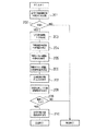
図3は、入出力端末116から信号帯域の制御要求の指示があった場合のソフトウェア制御部115の処理を示すフローチャートである。特に、制御要求が、音源接続要求や音源遮断要求である場合の処理を示すものである。
【0033】
図2に示す旧交換系(1〜3)から新交換系(4〜6)に加入者回線を切り替える場合、切替動作の途中においては、布線装置7内を、端末からの加入者回線が旧交換系(1〜3)及び新交換系(4〜6)の双方に接続する2重布線状態とするが、この2重布線状態にする前に、作業者は入出力端末116を用いて、信号帯域制御装置5Aに音源接続要求である信号帯域の制御要求を与える。また、布線装置7内の2重布線状態を、旧交換系(1〜3)の布線状態を解除して新交換系(4〜6)の布線状態だけにしたときには、作業者は入出力端末116を用いて、信号帯域制御装置5Aに音源遮断要求である信号帯域の制御要求を与える。
【0034】
ソフトウェア制御部115は、制御信号帯域の制御要求の受領により図3に示す一連の処理を開始すると、受領した信号帯域の制御要求を分析し、その制御要求が制御を行なっても良い要求であるか否かの整合性を確認する(ステップ201、202)。
【0035】
図1及び図2においては、図示の簡単化のために、例えば、加入者線振り分けモジュール5における遠隔多重装置側のインタフェース回路を省略しているが、複数の遠隔多重装置4と接続するインタフェース回路が当然に存在する。このインタフェース回路はパッケージ単位に構成されており、複数のパッケージが1ユニットを構成しており、ユニットも複数存在する。制御信号帯域の制御要求には、このようなパッケージやユニットを特定する情報も含まれているが、実装されていないユニットやパッケージに係る制御要求は、整合性がないものとされる。また、この実施例の場合、信号帯域の制御は、アナログ系伝送信号に対してのみ実行するようになされており、制御信号帯域の制御要求に係るパッケージやユニットがISDN系伝送信号についてのものであると、整合性がないものとされる。以上、整合性判断の一例を説明したが、このように、その制御要求が受け入れられるものか否かを判別する。
【0036】
受領した制御要求が、要求として整合していないものであると、その制御要求は異常と判断されて、一連の処理を異常であるとして終了する。この場合には、例えば、入出力端末116に異常である旨を通知して表示させる。
【0037】
制御要求が整合していると、ソフトウェア制御部115は、受領した制御要求に基づいて、受信信号帯域切替装置101の信号帯域の実際の動作モードを決定する(ステップ203)。
【0038】
この実施例の場合、動作モードとして、加入者回路駆動信号音源103をデータ回線切替回路102−1に接続させる加入者回路駆動モードと、無通話信号音源104をデータ回線切替回路102−3に接続させる無通話保証モードと、加入者回路駆動信号音源103及び又は無通話信号音源104のデータ回線切替回路102−1及び又は102−3との接続状態を解放するノーマルモード(NORMALモード)とが用意されており、ソフトウェア制御部105は、今回受領した制御要求がどの動作モードに関するものであるかを認識する。
【0039】
次に、ソフトウェア制御部115は、制御要求に係るデータ回線を決定し、決定したデータ回線についての情報をデータ回線情報メモリ114から全て検索する(ステップ204、205)。例えば、回線切替は局番単位(1万回線)で行なわれるため制御要求も局番を規定する情報等を含むが、遠隔多重装置4、及び、信号帯域制御装置5Aが搭載されている加入者線振り分けモジュール5間で授受する単位である、複数(32個)のタイムスロットでなるスーパーハンドリンググループの回線数はそれより少ない。そこで、ソフトウェア制御部115は、制御要求で規定された局番に対応するスーパーハンドリンググループ(所定数のデータ回線)を認識した後、信号帯域切替装置101内でのパス情報等のデータ回線情報をデータ回線情報メモリ114を検索して得る。
【0040】
そして、検索されたデータ回線情報(特にそのパス情報)に基づいて、加入者回路駆動信号音源103とデータ回線切替回路102−1との接続位置や遮断位置、及び又は、無通話信号音源104とデータ回線切替回路102−3との接続位置や遮断位置を決定する(ステップ206)。
【0041】
例えば、加入者回路駆動モードであれば、加入者回路駆動信号音源103とデータ回線切替回路102−1との接続位置を決定し、無通話保証モードであれば、無通話信号音源104とデータ回線切替回路102−3との接続位置を決定し、ノーマルモードであれば、加入者回路駆動信号音源103とデータ回線切替回路102−1との遮断位置、及び、無通話信号音源104とデータ回線切替回路102−3との遮断位置を決定する。
【0042】
なお、加入者線振り分けモジュール5は、上述したように、アナログ系端末からの伝送信号及びISDN系端末からの伝送信号をそれぞれ、アナログ系端末に対応した自動交換機6及び図示しないISDN系端末に対応した自動交換機に振り分けるものであるので、データ回線とパスとが1対1とに定まっており、データ回線が定まれば、パス従って上記接続位置が定まるものである。
【0043】
次に、信号帯域切替装置101を具体的にどのように動作させるかを決定した後、この決定結果と、上記で決定した接続位置とを元に、信号帯域切替装置101に対して、加入者回路駆動信号音源103及び無通話信号音源104の接続動作又は遮断動作を指示する(ステップ207、208)。
【0044】
そして、ソフトウェア制御部115は、信号帯域切替装置101が指示したように動作したか否かを判別し、正常に動作しない場合には一連の処理を異常として終了し、これに対して、正常に動作した場合には、音源の接続状況を信号帯域情報メモリ113に格納した後、一連の処理を終了させる(ステップ209、210)。
【0045】
図4は、この実施例の伝送信号の信号帯域を示すものである。伝送信号の帯域は、発呼や終話等の制御信号が挿入される制御信号帯域と、音声信号が挿入される音声帯域とからなり、スーパーハンドリンググループ単位に制御信号帯域及び音声帯域がまとめられている。この実施例の場合、加入者回路駆動信号音源103が発生した加入者回路駆動信号パターンは制御信号帯域に挿入されるようになされており、無通話信号音源104が発生した無通話状態を保証する無通話ビットパターンも制御信号帯域に挿入されるようになされている。
【0046】
図5は、入出力端末116から音源接続状況の通知要求の指示があった場合のソフトウェア制御部115の処理を示すフローチャートである。
【0047】
ソフトウェア制御部115は、音源接続状況の通知要求の受領により図5に示す一連の処理を開始すると、信号帯域情報メモリ113に格納されている音源の接続状況を全て取り出して、入出力端末116に転送して一連の処理を終了する(ステップ301、302)。これにより、入出力端末116は、音源の接続状況を表示する。
【0048】
従って、上記実施例によれば、回線を旧交換系(1〜3)から新交換系(4〜6)に切り替える際の布線装置7を2重布線状態にする前に、加入者回路駆動信号音源103及び無通話信号音源104をそれぞれデータ回線切替装置102−1及び102−3に接続させておけば、2重布線状態になっても、端末側には加入者回路駆動信号が送出されて加入者回路が加入者に対して給電を停止し、自動交換機6側には無通話を保証する信号が送出され、その移行時に、各部が誤動作したり一斉発呼したり無意味な音を発音させたりすることを防止できる。
【0049】
また、上記実施例によれば、加入者回路駆動信号音源103及び無通話信号音源104をそれぞれデータ回線切替装置102−1及び102−3に接続させることにより、回線を遮断することができるので、布線装置内の導通状態切替回路を物理的に非導通状態へ切替える作業が不要であって回線切替時の作業効率を高めることができる。実際上、布線装置7として、ジャンパ線の接続替えを遠隔制御できるロボットによって行なうものがあり、このような布線装置7を適用した場合には、加入者線振り分けモジュール5に対する入出力端末106からの布線替え操作によって、布線状態を変更することができ、この場合には布線装置7の近傍に作業者が不要となって一段と作業効率を高めることができるようになる。
【0050】
さらに、上記実施例によれば、音源の接続状況を一元管理し、必要に応じて入出力端末116に転送して表示させる機能を有するので、この面からも、作業手順の簡素化及び作業効率の向上を期待できる。
【0051】
さらにまた、上記実施例によれば、加入者回路駆動信号音源103だけの接続制御や無通話信号音源104だけの接続制御も実行できるので、加入者回線を収容する交換系を切り替える場合だけでなく、回線増設時や保守点検時などに、その保守内容に応じた多様の信号帯域の制御を実行することができる。
【0052】
なお、上記実施例においては、信号帯域制御装置5Aを加入者線振り分けモジュール5に設けたものを示したが、加入者系交換装置内に設けるようにしても良く、また、単独の装置として設けるようにしても良い。
【0053】
また、上記実施例においては、加入者回路駆動信号音源103がデータ回線切替装置102−1のデータ回線切替装置102−2側の入出力端子に接続され、無通話信号音源104がデータ回線切替装置102−3のデータ回線切替装置102−2側の入出力端子に接続されているものを示したが、本発明は、この接続位置に限定されず、例えば、加入者回路駆動信号音源103をデータ回線切替装置102−3の自動交換装置6側の入出力端子に接続し、無通話信号音源104をデータ回線切替装置102−1の遠隔多重装置4側の入出力端子に接続するようにしても良い。
【0054】
さらに、信号帯域切替装置101も、T−S−Tスイッチ構成を利用したものに限定されるものではない。
【0055】
【発明の効果】
以上のように、本発明によれば、交換装置間での回線移行時等の保守時のように、複数の回線の切断、接続が必要な場合に、それら回線の切断、接続を、布線装置内の導通状態切替装置に対する物理的な操作によらず、しかも、誤動作させる可能性がある不要な信号の送出を伴うことなく実行できるようになる。
【図面の簡単な説明】
【図1】実施例の信号帯域制御装置の構成を示す機能ブロック図である。
【図2】実施例の信号帯域制御装置が適用されている交換システムを示すブロック図である。
【図3】実施例の信号帯域制御装置の動作フローチャートである。
【図4】実施例の信号帯域の説明図である。
【図5】実施例の音源接続状況の転送時の動作フローチャートである。
【符号の説明】
5A…信号帯域制御装置、101…信号帯域切替装置、102−1〜102−3…データ回線切替装置、103…加入者回路駆動信号音源、104…無通話信号音源、106…装置制御部、107…信号帯域制御部、108…データ回線情報管理部、109…信号帯域情報管理部、110…信号帯域制御モード決定部、111…入出力端末受付部、112…信号帯域情報通知制御部、113…信号帯域情報メモリ、114…データ回線情報メモリ、115…ソフトウェア制御部、116…入出力端末。[0001]
[Industrial applications]
The present invention relates to a signal band control device for controlling a signal band when a line is switched from an old switching device to a new switching device.
[0002]
[Prior art]
It is often the case that a switching device that has been used is replaced with a new switching device whose function has been improved. In this case, the switching device accommodating the line is transferred from the old switching device to the new switching device.
[0003]
When the line is transferred from the old switching device to the new switching device as described above, the line is temporarily double-wired in the wiring device (MDF) interposed between the accommodation terminal and the switching device, The line temporarily exists in both directions of the old switching device and the new switching device. In such a state, in order to stop the new switching device from detecting a call from the terminal side and to assure the effect of the construction work of the new switching device on the line on the terminal side, the double cloth is used. Before the line state is established, it is necessary to disconnect the line of the new switching device.
[0004]
Conventionally, the line of such a new switching device is disconnected by physically switching the conduction state switching circuit in the wiring device to a non-conduction state.
[0005]
After that, the state is shifted to the double wiring state, and the line of the old switching device is disconnected and the line of the new switching device is connected by the conduction state switching circuit, and the line is shifted to the new switching device.
[0006]
[Problems to be solved by the invention]
However, the physical switching of the conduction state switching circuit is manually performed, so that the operation is very complicated and the operation efficiency is low. Physical switching of the conduction state switching circuit is actually repeated for each station number (10,000 lines).
[0007]
Further, when the conduction state switching circuit in the wiring device is physically switched to the non-conduction state or when the conduction state is switched to the conduction state, all the lines (10,000 lines) involved in the switching are switched in the new switching device. However, noise may be detected at the same time as a call signal, and if an abnormal condition occurs in the wiring equipment on the terminal side, there is a possibility that a call failure such as crosstalk may occur. there were.
[0008]
Therefore, disconnection and connection of the line of the new switching device at the time of line transfer between switching devices do not depend on physical operation on the conduction state switching device, and also involve transmission of unnecessary signals that may cause malfunction. There is a need for a new method that can execute transmission of a signal that can verify an abnormal wiring state in a wiring device without the need for such a method.
[0009]
[Means for Solving the Problems]
In order to solve such a problem, the present invention is a signal band control device that is inserted on a path between a wiring device and a switching device and controls information inserted into a signal band of a line on the path. When the same line from the switching device to the wiring device is disconnected at the switching device side and the wiring device side, the power supply from at least the subscriber circuit to the terminal side is stopped when the same circuit from the switching device to the wiring device is disconnected. a subscriber circuit driving signal source for generating a subscriber circuit driving signal for a no-call guarantee signal source for generating a non-call guarantee signal to ensure no call, according to instructions from the external device, the wiring apparatus side For signal bands of a plurality of predetermined lines, insertion of a subscriber circuit drive signal generated by the subscriber circuit drive signal sound source , subscriber circuit drive signal insertion control means for controlling non-insertion, and according to an instruction from an external device, Exchange With respect to the signal band of the plurality of predetermined lines 置側, it provides a signal band control device characterized by having a non-call guarantee signal insertion control means for controlling the insertion of the idle calling guarantee signal, the non-insertion.
[0010]
[Action]
In the signal band control device according to the present invention, when an instruction to insert both signals is given from an external device, the subscriber circuit drive signal insertion control means applies the signal band to a plurality of predetermined lines on the wiring device side according to the instruction. insert controls the subscriber line interface circuit driving signal Te, is sent to the subscriber circuit driving signal to the plurality of predetermined lines, also, no call guarantee signal insertion control means, the switching device side according to the instruction of the plurality of predetermined lines to the signal band, by inserting control idle calling assurance tone, it is sent a no-call guarantee signal to the plurality of predetermined lines.
[0011]
Therefore, in this signal band control device, even if it is the same line, the line portion on the wiring device side and the line portion on the switching device side are surely separated, and the subscriber line drive signal and no Even if the call guarantee signal is transmitted and disconnected, it is possible to prevent malfunctions in the wiring device, the terminal, and the switching device.
[0012]
For example, when replacing the exchange device, if the state of the wiring in the wiring device is changed to the double wiring state for the new exchange device and the old exchange device by using an external device, such a state is obtained. Even if the state shifts to the double wiring state, malfunctions and the like can be reliably prevented, and the work of interrupting the conduction state on the new replacement device side can be eliminated.
[0013]
Each of the subscriber circuit drive signal insertion control means and the non-talk signal insertion control means, when instructed by the external device to not insert both signals, drives the subscriber circuit with respect to the signal bands of a plurality of predetermined lines on the wiring device side. The insertion of a signal and the insertion of a call signal into a signal band of a plurality of predetermined lines on the switching device side are stopped and interrupted.
[0014]
In the above, the operation when the connection or cutoff instruction to both sound sources is given from the external device has been described. However, the operation may be performed by individually giving the connection or cutoff instruction to each sound source from the external device.
[0015]
【Example】
Hereinafter, an embodiment of the present invention will be described in detail with reference to the drawings.
[0016]
FIG. 2 shows an example of an arrangement of various devices related to line transfer between switching devices. In FIG. 2, in this example, a switching system including a remote multiplexing device (RT) 1, a central office (CT) 2 and an automatic exchange (for example, a D70 type automatic exchange) 3 is replaced with a new type remote multiplexing device (RT) 4, This figure shows a case where the switching system is switched to a switching system composed of a subscriber line sorting module (LXM) 5 and a new type of automatic exchange (for example, a new type of D70 type automatic exchange) 6, and both exchange systems are common wiring equipment (MDF). The line from the terminal is switched to the new switching system by switching the wiring state inside the wiring device 7.
[0017]
Here, the subscriber
[0018]
Since the transmission lines before and after the subscriber
[0019]
FIG. 1 shows a functional block configuration of the signal band control device 5A. In FIG. 1, the signal band control device 5A is mainly composed of a signal
[0020]
The signal
[0021]
Each of the three data line switching devices 102-1, 102-2, and 102-3 includes, for example, a T switch (time division switch), an S switch (space switch), and a T switch. The data line switching devices 102-1, 102-2, and 102-3 cooperate to distribute the transmission signal from the terminal and perform the reverse process. The data line switching device 102-1 switches the signal band of the data line on the remote multiplexing device 4 side in relation to switching of the switching system. The data line switching device 102-3 switches the signal band of the data line on the
[0022]
The subscriber circuit drive signal sound source 103 generates a subscriber circuit drive signal (for example, a signal having a predetermined bit pattern). The subscriber circuit drive signal sound source 103 is connected to an input / output terminal of the data line switching device 102-1 on the side of the data line switching device 102-2. In other words, depending on the path state of the data line switching device 102-1, the subscriber circuit drive signal generated by the subscriber circuit drive signal sound source 103 is transmitted to the data line of the remote multiplexing device 4 (therefore, the wiring device 7). Has been made possible.
[0023]
The non-speech signal sound source 104 generates a control signal (for example, a signal having a predetermined bit pattern) that guarantees no-speech. The no-communication signal source 104 is connected to an input / output terminal of the data line switching device 102-3 on the side of the data line switching device 102-2. In other words, depending on the path state of the data line switching device 102-3, a control signal for guaranteeing the non-communication generated by the non-communication signal source 104 can be transmitted to the data line of the
[0024]
The software control unit 115 includes a CPU, a main memory (MM), various input / output ports, and the like in terms of hardware. The software control unit 115 is divided into functions in terms of software related to switching of the switching system which is developed in the main memory and executed by the CPU, and is divided into a device control unit 106, a signal band control unit 107, a data line
[0025]
The input / output
[0026]
The signal band control
[0027]
The signal band
[0028]
The data line
[0029]
The signal band control unit 107 controls the actual control mode of the signal band determined by the signal band control
[0030]
The device control unit 106 directly controls the operation of the signal
[0031]
The signal band information
[0032]
FIG. 3 is a flowchart showing the processing of the software control unit 115 when the input /
[0033]
When the subscriber line is switched from the old switching system (1-3) to the new switching system (4-6) shown in FIG. 2, during the switching operation, the subscriber line from the terminal passes through the wiring device 7. In the double wiring state connected to both the old switching system (1-3) and the new switching system (4-6), before making the double wiring state, the operator sets the input /
[0034]
When the software control unit 115 starts the series of processes shown in FIG. 3 upon receiving the control signal band control request, the software control unit 115 analyzes the received signal band control request, and the control request is a request that may be controlled. It is checked whether there is consistency (
[0035]
In FIG. 1 and FIG. 2, for simplicity of illustration, for example, the interface circuit on the side of the remote multiplexer in the subscriber
[0036]
If the received control request does not match as the request, the control request is determined to be abnormal, and a series of processing is terminated as abnormal. In this case, for example, the input /
[0037]
If the control requests match, the software control unit 115 determines the actual operation mode of the signal band of the received signal
[0038]
In the case of this embodiment, the subscriber circuit drive signal source 103 is connected to the data line switching circuit 102-1 as the operation mode, and the no-talk signal source 104 is connected to the data line switch circuit 102-3. A normal mode (NORMAL mode) for releasing the connection state of the subscriber circuit drive signal source 103 and / or the non-communication signal source 104 with the data line switching circuits 102-1 and / or 102-3 is provided. The software control unit 105 recognizes which operation mode the control request received this time relates to.
[0039]
Next, the software control unit 115 determines a data line related to the control request, and searches the data line information memory 114 for all information on the determined data line (
[0040]
Then, based on the searched data line information (particularly, the path information), the connection position or cutoff position between the subscriber circuit drive signal sound source 103 and the data line switching circuit 102-1 and / or the non-communication signal sound source 104 A connection position and a disconnection position with the data line switching circuit 102-3 are determined (step 206).
[0041]
For example, in the case of the subscriber circuit drive mode, the connection position between the subscriber circuit drive signal sound source 103 and the data line switching circuit 102-1 is determined. The connection position with the switching circuit 102-3 is determined. If the connection mode is the normal mode, the cutoff position between the subscriber circuit drive signal sound source 103 and the data line switching circuit 102-1 and the non-speech signal sound source 104 and the data line switching. The interruption position with the circuit 102-3 is determined.
[0042]
As described above, the subscriber
[0043]
Next, after determining how to specifically operate the signal
[0044]
Then, the software control unit 115 determines whether or not the signal
[0045]
FIG. 4 shows a signal band of a transmission signal of this embodiment. The transmission signal band is composed of a control signal band in which control signals such as calling and ending calls are inserted, and a voice band in which a voice signal is inserted, and the control signal band and the voice band are grouped for each super handling group. ing. In the case of this embodiment, the subscriber circuit drive signal pattern generated by the subscriber circuit drive signal sound source 103 is inserted into the control signal band, thereby guaranteeing a no-communication state in which the no-communication signal source 104 is generated. A non-communication bit pattern is also inserted into the control signal band.
[0046]
FIG. 5 is a flowchart showing the processing of the software control unit 115 in the case where the input /
[0047]
When the software control unit 115 starts the series of processes illustrated in FIG. 5 upon receipt of the notification request for the sound source connection status, the software control unit 115 extracts all the connection statuses of the sound sources stored in the signal band information memory 113 and sends them to the input /
[0048]
Therefore, according to the above-described embodiment, before the wiring device 7 is switched from the old switching system (1 to 3) to the new switching system (4 to 6), the subscriber circuit is switched to the double wiring state. If the drive signal sound source 103 and the non-speech signal sound source 104 are connected to the data line switching devices 102-1 and 102-3, respectively, the subscriber circuit drive signal will remain on the terminal side even in the double-wired state. Then, the subscriber's circuit stops supplying power to the subscriber, and a signal is transmitted to the
[0049]
Also, according to the above embodiment, the line can be cut off by connecting the subscriber circuit drive signal sound source 103 and the no-communication signal sound source 104 to the data line switching devices 102-1 and 102-3, respectively. There is no need to physically switch the conduction state switching circuit in the wiring device to the non-conduction state, and the work efficiency at the time of line switching can be improved. Actually, as the wiring device 7, there is a robot which can remotely change the connection of the jumper line by using a robot. When such a wiring device 7 is applied, the input / output terminal 106 for the subscriber
[0050]
Furthermore, according to the above embodiment, since the function of centrally managing the connection state of the sound source and transferring it to the input /
[0051]
Furthermore, according to the above embodiment, the connection control of only the subscriber circuit drive signal sound source 103 and the connection control of the non-speech signal source 104 alone can be executed. In addition, when a line is added or maintenance is performed, various signal bands can be controlled in accordance with the contents of the maintenance.
[0052]
In the above embodiment, the signal band control device 5A is provided in the subscriber
[0053]
Further, in the above embodiment, the subscriber circuit drive signal sound source 103 is connected to the input / output terminal of the data line switching device 102-1 on the side of the data line switching device 102-2, and the no-communication signal source 104 is connected to the data line switching device 102-1. Although the one connected to the input / output terminal of the data line switching device 102-2 of the 102-3 is shown, the present invention is not limited to this connection position. It is also possible to connect the line switching device 102-3 to the input / output terminal on the
[0054]
Further, the signal
[0055]
【The invention's effect】
As described above, according to the present invention, as in the time of maintenance when the line Transfers between changer, cleavage of a plurality of lines, if the connection is required, cutting their lines, connections, wiring This can be performed without relying on physical operation on the conduction state switching device in the device, and without sending unnecessary signals that may cause malfunction.
[Brief description of the drawings]
FIG. 1 is a functional block diagram illustrating a configuration of a signal band control device according to an embodiment.
FIG. 2 is a block diagram illustrating a switching system to which the signal band control device according to the embodiment is applied.
FIG. 3 is an operation flowchart of the signal band control device of the embodiment.
FIG. 4 is an explanatory diagram of a signal band according to the embodiment.
FIG. 5 is an operation flowchart when transferring a sound source connection state according to the embodiment;
[Explanation of symbols]
5A: Signal band control device, 101: Signal band switching device, 102-1 to 102-3: Data line switching device, 103: Subscriber circuit drive signal sound source, 104: Non-communication signal sound source, 106: Device control unit, 107 ························································································································································································································· Signal band information memory, 114: data line information memory, 115: software control unit, 116: input / output terminal.
Claims (2)
加入者回路を駆動制御し、上記交換装置から布線装置にいたる同一の回線が交換装置側と布線装置側で切り離された場合において少なくとも当該加入者回路から端末側への給電を停止させるための加入者回路駆動信号を発生する加入者回路駆動信号音源と、
無通話を保証する無通話保証信号を発生する無通話保証信号音源と、
外部装置からの指示に従って、布線装置側の複数の所定回線の信号帯域に対し、上記加入者回路駆動信号音源が発生する加入者回路駆動信号の挿入、非挿入を制御する加入者回路駆動信号挿入制御手段と、
外部装置からの指示に従って、交換装置側の複数の所定回線の信号帯域に対し、上記無通話保証信号の挿入、非挿入を制御する無通話保証信号挿入制御手段とを有することを特徴とする信号帯域制御装置。A signal band control device that is inserted on a path between the wiring device and the switching device and controls information inserted into a signal band of a line on the path,
To control the driving of the subscriber's circuit and to stop the power supply from at least the subscriber's circuit to the terminal when the same line from the switching device to the wiring device is disconnected at the switching device side and the wiring device side. A subscriber circuit drive signal sound source for generating a subscriber circuit drive signal of
And a non-call guarantee signal source for generating a non-call guarantee signal to guarantee the non-call,
A subscriber circuit drive signal for controlling insertion / non-insertion of a subscriber circuit drive signal generated by the subscriber circuit drive signal sound source with respect to signal bands of a plurality of predetermined lines on the wiring device side in accordance with an instruction from an external device. Insertion control means;
In accordance with an instruction from the external device, with respect to the signal band of the plurality of predetermined lines of the switching device side, the signal is characterized by having a non-call guarantee signal insertion control means for controlling the insertion of the idle calling guarantee signal, the non-insertion Bandwidth control device.
外部装置からの指示に従って、上記信号挿入状況管理手段が一元管理している挿入状況情報を上記外部装置に転送する挿入状況転送手段とをさらに有することを特徴とする請求項1に記載の信号帯域制御装置。Centralized management of the insertion and non-insertion status of the subscriber circuit drive signal into the signal band of the line on the wiring device side, and the insertion and non-insertion status of the no-voice guarantee signal on the signal band of the line on the switching device side Signal insertion status management means to perform
In accordance with an instruction from the external device, the signal band according to claim 1, further comprising an insertion status information the signal insertion state management unit is centrally manages the insertion status transfer means for transferring to the external device Control device.
Priority Applications (1)
| Application Number | Priority Date | Filing Date | Title |
|---|---|---|---|
| JP00462895A JP3539779B2 (en) | 1995-01-17 | 1995-01-17 | Signal band control device |
Applications Claiming Priority (1)
| Application Number | Priority Date | Filing Date | Title |
|---|---|---|---|
| JP00462895A JP3539779B2 (en) | 1995-01-17 | 1995-01-17 | Signal band control device |
Publications (2)
| Publication Number | Publication Date |
|---|---|
| JPH08195808A JPH08195808A (en) | 1996-07-30 |
| JP3539779B2 true JP3539779B2 (en) | 2004-07-07 |
Family
ID=11589302
Family Applications (1)
| Application Number | Title | Priority Date | Filing Date |
|---|---|---|---|
| JP00462895A Expired - Lifetime JP3539779B2 (en) | 1995-01-17 | 1995-01-17 | Signal band control device |
Country Status (1)
| Country | Link |
|---|---|
| JP (1) | JP3539779B2 (en) |
-
1995
- 1995-01-17 JP JP00462895A patent/JP3539779B2/en not_active Expired - Lifetime
Also Published As
| Publication number | Publication date |
|---|---|
| JPH08195808A (en) | 1996-07-30 |
Similar Documents
| Publication | Publication Date | Title |
|---|---|---|
| CA2280147C (en) | Redundancy arrangement for telecommunications system | |
| JPH09507982A (en) | Signal protection and monitoring system | |
| KR960002469B1 (en) | Isdn communication system maintenance in the impedance by using present and reserved isdn communication device | |
| JP3539779B2 (en) | Signal band control device | |
| JPH1169393A (en) | T-s-t three-stage switch control system | |
| EP1206081B1 (en) | Apparatus for the transmission and/or reception of data, and method for controlling this apparatus | |
| US5459772A (en) | External apparatus for monitoring a communication system | |
| KR19990050421A (en) | Structure of communication connection part and transfer control method with activation N + 1 redundancy structure of access communication system considering line redundancy | |
| JP2005535252A (en) | Telecommunications network and method for upgrading the same | |
| KR100211992B1 (en) | A method of switch configuration information cahnge from 1:n protection in facility module protection for broadband digital cross-connect system | |
| JP2507609B2 (en) | ISDN subscriber interface equipment | |
| JP2867865B2 (en) | Protection line switching control method | |
| US7075888B1 (en) | Method for operating interface modules in an ATM communications device | |
| KR100258767B1 (en) | Method and device for automatic recovery of persistent virtual connection in asynchronous transfer mode multimedia switching system | |
| KR100428766B1 (en) | Subscriber Switching Device of ADSL and Subscriber Port and Subscriber Unit Switching Method Utilizing | |
| US6614901B1 (en) | Method and system for a scaleable virtual switch | |
| KR940008779B1 (en) | Common channel signalling method | |
| JPS6148249A (en) | Line switching device | |
| JP2000069162A (en) | Line interface system of n+1 constitution | |
| JPH11284589A (en) | Redundancy configuration system for line terminating panel of time division multiplexer | |
| JPH0723108A (en) | Standby signal device selecting method | |
| KR20000025698A (en) | Switch module | |
| JPH025656A (en) | Method for constructing communication network | |
| EP0891657A1 (en) | System, arrangement and method relating to protection in a communications system and a telecommunications system with a protection arrangement | |
| JPH04256264A (en) | Talkie transmission system in telephone exchange network |
Legal Events
| Date | Code | Title | Description |
|---|---|---|---|
| TRDD | Decision of grant or rejection written | ||
| A01 | Written decision to grant a patent or to grant a registration (utility model) |
Free format text: JAPANESE INTERMEDIATE CODE: A01 Effective date: 20040323 |
|
| A61 | First payment of annual fees (during grant procedure) |
Free format text: JAPANESE INTERMEDIATE CODE: A61 Effective date: 20040323 |
|
| R150 | Certificate of patent or registration of utility model |
Free format text: JAPANESE INTERMEDIATE CODE: R150 |
|
| FPAY | Renewal fee payment (event date is renewal date of database) |
Free format text: PAYMENT UNTIL: 20080402 Year of fee payment: 4 |
|
| FPAY | Renewal fee payment (event date is renewal date of database) |
Free format text: PAYMENT UNTIL: 20090402 Year of fee payment: 5 |
|
| FPAY | Renewal fee payment (event date is renewal date of database) |
Free format text: PAYMENT UNTIL: 20100402 Year of fee payment: 6 |
|
| FPAY | Renewal fee payment (event date is renewal date of database) |
Free format text: PAYMENT UNTIL: 20100402 Year of fee payment: 6 |
|
| FPAY | Renewal fee payment (event date is renewal date of database) |
Free format text: PAYMENT UNTIL: 20110402 Year of fee payment: 7 |
|
| FPAY | Renewal fee payment (event date is renewal date of database) |
Free format text: PAYMENT UNTIL: 20110402 Year of fee payment: 7 |
|
| FPAY | Renewal fee payment (event date is renewal date of database) |
Free format text: PAYMENT UNTIL: 20130402 Year of fee payment: 9 |
|
| FPAY | Renewal fee payment (event date is renewal date of database) |
Free format text: PAYMENT UNTIL: 20130402 Year of fee payment: 9 |
|
| FPAY | Renewal fee payment (event date is renewal date of database) |
Free format text: PAYMENT UNTIL: 20140402 Year of fee payment: 10 |
|
| S111 | Request for change of ownership or part of ownership |
Free format text: JAPANESE INTERMEDIATE CODE: R313117 |
|
| R250 | Receipt of annual fees |
Free format text: JAPANESE INTERMEDIATE CODE: R250 |
|
| S531 | Written request for registration of change of domicile |
Free format text: JAPANESE INTERMEDIATE CODE: R313531 |
|
| R350 | Written notification of registration of transfer |
Free format text: JAPANESE INTERMEDIATE CODE: R350 |
|
| EXPY | Cancellation because of completion of term |