JP3239237U - Series of vertical stoppers for high-speed train bogies - Google Patents
Series of vertical stoppers for high-speed train bogies Download PDFInfo
- Publication number
- JP3239237U JP3239237U JP2022002494U JP2022002494U JP3239237U JP 3239237 U JP3239237 U JP 3239237U JP 2022002494 U JP2022002494 U JP 2022002494U JP 2022002494 U JP2022002494 U JP 2022002494U JP 3239237 U JP3239237 U JP 3239237U
- Authority
- JP
- Japan
- Prior art keywords
- series
- vertical
- layer
- stoppers
- bogies
- Prior art date
- Legal status (The legal status is an assumption and is not a legal conclusion. Google has not performed a legal analysis and makes no representation as to the accuracy of the status listed.)
- Active
Links
Images


Landscapes
- Vibration Dampers (AREA)
Abstract
【課題】車軸ボックスとの共振を回避することができる高速鉄道列車の台車用一連垂直ストッパーを提供する。【解決手段】重力加速度の方向が垂直方向として定義され、高速鉄道列車の進行方向が縦方向(長手方向)である、高速鉄道列車台車用の一連垂直ストッパーであり、第1端部100と、第2端部200と、接続部300と、開口溝400とを含む。第1端部は台車と協調し、縦方向に平行に伸びている。第2端部は高速鉄道列車のアクスルボックスに接続され、縦方向に平行である。接続部は第1端部と第2端部を接続し、垂直に平行で「工」字形の一連垂直ストッパーを形成する。開口溝は、一連垂直ストッパーの固有周波数を変更するために、材料を除去する方法で一連垂直ストッパーに形成される。【選択図】図3A series of vertical stops for bogies of high-speed rail trains capable of avoiding resonance with axle boxes. A series of vertical stops for a high-speed rail bogie, wherein the direction of gravitational acceleration is defined as vertical and the direction of travel of the high-speed rail train is longitudinal (longitudinal); It includes a second end 200 , a connecting portion 300 and an open groove 400 . The first end cooperates with the carriage and extends parallel to the longitudinal direction. The second end is connected to the axle box of the high speed rail train and is longitudinally parallel. A connecting portion connects the first end and the second end to form a series of vertically parallel, "-"-shaped vertical stops. An open groove is formed in the series of vertical stoppers in a manner that removes material to change the natural frequency of the series of vertical stoppers. [Selection drawing] Fig. 3
Description
本考案は、高速鉄道列車台車の技術に関し、特に、高速鉄道列車の台車用一連垂直ストッパーに関するものである。 TECHNICAL FIELD The present invention relates to the technology of high-speed rail train bogies, and more particularly to a series of vertical stoppers for high-speed rail bogies.
高速鉄道列車の台車と車軸ボックスの相対運動を一定範囲内に保ち、列車運行の安定性と安全性を向上させるためには、通常、列車の車軸ボックスに垂直変位を制限する部品を設定する必要がある。1950年、Nelsonら(Safety support for brake beams,US 2,496,015,1950)はチェーン構造を使用して台車のブレーキビーム(brake beam)を台車に接続し、ブレーキビームの最大垂直変位と脱落を制限した。旅客列車では、車軸ボックスの脱落を防ぎ、最大垂直変位を制限するために、逆U字型の安全ホイストが一般的に使用される。ただし、台車のプレート式安全ハンガーは、列車の運行中に縦方向の動的応力が交互に大きくなるため、破損しやすく、垂直変位の制限が無効になる。 In order to keep the relative motion between bogies and axle boxes in high-speed trains within a certain range and improve the stability and safety of train operation, it is usually necessary to set up parts that limit vertical displacement in the axle boxes of trains. There is In 1950, Nelson et al. (Safety support for brake beams, US 2,496,015, 1950) used a chain structure to connect a truck brake beam to the truck to limit maximum vertical displacement and dropout of the brake beam. On passenger trains, inverted U-shaped safety hoists are commonly used to prevent axle boxes from falling out and limit maximum vertical displacement. However, plate safety hangers on bogies are prone to failure due to alternating dynamic stresses in the longitudinal direction during train operation, defeating the vertical displacement limitation.
高速鉄道列車に関しては、CRH5列車は中国の高速鉄道列車のモデルであり、中国の低温地域を歩くのに適しており、その運転速度は時速250キロメートルの最高速度に達することができる。CRH5列車の台車には、図1に示すように、台車と車軸ボックスの間の過度の垂直相対変位を回避するために、一連垂直ストッパーが設けられている。ただし、これらのコンポーネントは、動作中の実際のルートの影響により横方向に破壊されやすく、機能障害が発生する。したがって、一連垂直ストッパーの構造最適化は、高速鉄道列車工学装置の設計において解決すべき緊急の問題であり、高速運転における列車の安定性と安全性にとって大きな実用的価値と重要性を持っている。 As for high-speed rail trains, the CRH5 train is a model of China's high-speed rail train, suitable for walking in China's low-temperature regions, and its driving speed can reach a maximum speed of 250 kilometers per hour. The bogies of the CRH5 train are provided with a series of vertical stops, as shown in Figure 1, to avoid excessive vertical relative displacement between the bogies and the axle boxes. However, these components are susceptible to lateral destruction under the influence of the actual route in operation, resulting in functional failure. Therefore, structural optimization of a series of vertical stoppers is an urgent problem to be solved in the design of high-speed railway train engineering equipment, and has great practical value and significance for train stability and safety in high-speed operation. .
図1及びに図2示すように、図1は、高速鉄道列車台車の一連垂直ストッパーの設置位置の概略図であり、図2は、既存の一連垂直ストッパーの概略三次元構造図である。CRH5高速列車の台車の最初の一連垂直ストッパーは高炭素鋼S355J2Gで、表面にFe/Znが噴霧されている。一連垂直ストッパーは、第1端部91、固定部92、及び接続部93を含む、「工」形状を有する一体型ブロックの形状である。ここで、接続部93は、第1端部91と固定部92との中間位置に接続されている。固定部92の両端にはそれぞれボルト穴が設けられており、一連垂直ストッパーの固定部92は、ボルトを接続することにより車軸ボックス10のトランジションカバー12に固定することができる。一連垂直ストッパーの第1端部91は、台車11の上に吊り下げられており、台車11との間に一定のギャップがある。ギャップは、台車と車軸ボックスとの間の垂直相対変位である。台車11の垂直方向の変位がギャップを超えると、台車11は第1端部91によってブロックされ、それにより列車の運行の滑らかさと安全性を向上させる。
As shown in FIGS. 1 and 2, FIG. 1 is a schematic diagram of the installation position of a series of vertical stoppers on a high-speed railway bogie, and FIG. 2 is a schematic three-dimensional structural diagram of an existing series of vertical stoppers. The first series of vertical stoppers on the bogies of the CRH5 high-speed train are high-carbon steel S355J2G, with Fe/Zn sprayed on the surface. A series of vertical stops are in the form of a one-piece block having a "engine" shape, including a
既存の一連垂直ストッパーの設計では、台車と車軸ボックスの間の垂直方向の相対変位を効果的に制限することができる。ただし、一連垂直ストッパーまたは車軸ボックスの固有振動数(たとえば、主振動周波数と二次固有振動数)はすべて固定レベルであり、これはその構造に固有の特性である。列車の車軸ボックス構造の形状と材質によって、車軸ボックスの固有振動数レベルが決まる。従来の一連垂直ストッパーの構造形状と材質も、一連垂直ストッパーの固有振動数レベルを決定する。従来の一連垂直ストッパーの固有振動数は、運転中の列車台車の上部車軸ボックスの振動数に非常に近く、共振現象が発生しやすくなっている。共振が発生すると、一連垂直ストッパーの振動振幅が急激に増幅され、大きな動的応力が発生し、一連垂直ストッパーが突然破損した。一連垂直ストッパーが横方向に曲がって破損した場合、上下運動中の使用中の台車の垂直方向の相対変位は制限されなくなる。さらに、垂直変位リミッターと車軸ボックスも脱落し、列車が脱線したり、転倒したりする可能性がある。Liu Zhiyuan(センメトロ2号線の安全クレーンシリーズの改良設計、山東工業技術7(2015):40-40)らは、接続部の厚さを増やして1次固有振動数を増やし、安全サスペンション構造を最適化して、共振によって引き起こされる破壊の問題を解決することを提案した。ただし、CRH5高速列車の一連垂直ストッパーの場合、実際の台車構造では、一連垂直ストッパーのサイズは、車軸ボックスのトランジションカバーのスロットのサイズと厚さの増加によって制限される。その結果、部品を台車に取り付けることができなくなる。 Existing series vertical stop designs can effectively limit the vertical relative displacement between the truck and the axle box. However, the eigenfrequencies (eg, primary and secondary eigenfrequencies) of a series of vertical stops or axle boxes are all at a fixed level, which is an inherent property of their construction. The shape and materials of the train axle box structure determine the natural frequency level of the axle box. The structural shape and materials of conventional vertical stopper series also determine the natural frequency level of the vertical stopper series. The natural frequency of the conventional series vertical stopper is very close to the frequency of the upper axle box of the train bogie during operation, which is prone to the resonance phenomenon. When resonance occurred, the vibration amplitude of the series of vertical stoppers was amplified abruptly, causing a large dynamic stress and causing the series of vertical stoppers to break suddenly. If the series of vertical stops is bent laterally and broken, the relative vertical displacement of the carriage in use during up-and-down motion becomes unrestricted. In addition, vertical displacement limiters and axle boxes can also fall off, causing trains to derail or overturn. Liu Zhiyuan (Improved Design of Safety Crane Series for Sen Metro Line 2, Shandong Industrial Technology 7 (2015): 40-40) et al. increased the thickness of the joint to increase the primary natural frequency and optimized the safety suspension structure proposed to solve the problem of destruction caused by resonance. However, for CRH5 high-speed train series vertical stoppers, in the actual bogie structure, the size of series vertical stoppers is limited by the increased slot size and thickness of the axle box transition cover. As a result, the parts cannot be attached to the truck.
従来技術の上記の問題を解決するために、本考案の目的は、車軸ボックスとの共振を回避することができる新しいタイプの高ダンピング内蔵の高速鉄道列車の台車用一連垂直ストッパーを提供することである。 In order to solve the above problems of the prior art, the object of the present invention is to provide a series of vertical stoppers for bogies of high-speed rail trains with a new type of built-in high damping, which can avoid resonance with axle boxes. be.
本考案の一態様によれば、高速鉄道列車の台車用一連垂直ストッパーは重力加速度の方向を垂直方向、高速鉄道の進行方向を縦方向と定義して、第1端部、第2端部、接続部、開口溝を含み、前記第1端部は台車と協調し、縦方向に平行に伸び、前記第2端部は高速鉄道列車の車軸ボックスに接続され、縦方向に平行に伸び、前記接続部は第1端部と第2端部を接続し、垂直方向に平行であり、「工」字形一連垂直ストッパーを形成し、前記開口溝は一連垂直ストッパーの固有振動数を変更するために、材料を除去する方法で一連垂直ストッパーに形成される。 According to one aspect of the present invention, a series of vertical stoppers for bogies of high-speed railway trains has a first end, a second end, a joint, comprising an open groove, said first end cooperating with a bogie and extending longitudinally parallel, said second end being connected to an axle box of a high-speed rail train and extending longitudinally parallel, said The connecting part connects the first end and the second end, is parallel to the vertical direction, and forms a series of vertical stoppers in the shape of a square, and the opening groove is for changing the natural frequency of the series of vertical stoppers. , formed into a series of vertical stops in a manner that removes material.
本考案の一実施形態によれば、前記一連垂直ストッパーは、少なくとも1つの開口溝を含み、前記開口溝は、材料を除去する方法で、垂直方向に沿って一連垂直ストッパーに形成される。 According to one embodiment of the present invention, said series of vertical stoppers comprises at least one open groove, said opening grooves being formed in said series of vertical stoppers along a vertical direction by a method of removing material.
本考案の一実施形態によれば、前記一連垂直ストッパーは制振層をさらに含み、前記制振層は開口溝に接着剤を充填することにより形成される。 According to an embodiment of the present invention, the series of vertical stoppers further comprises a damping layer, and the damping layer is formed by filling the opening grooves with an adhesive.
本考案の一実施形態によれば、前記開口溝は、第1端部と接続部を上下方向に貫通し、第2端部の少なくとも一部を貫通している。 According to one embodiment of the present invention, the opening groove vertically penetrates the first end and the connecting portion, and penetrates at least a part of the second end.
本考案の一実施形態によれば、前記第2端部を垂直方向に貫通する前記開口溝の高さH1と前記第2端部全体の高さHとの関係は、

本考案の一実施形態によれば、前記開口溝の縦方向の長さは、前記第1端部の縦方向の長さに等しく、前記接続部の縦方向の長さに等しく、前記開口溝により、前記第1端部は同形の第1端部第1層と第1端部第2層に分割され、前記接続部は同形状の接続部第1層と接続部第2層に分割される。 According to one embodiment of the present invention, the longitudinal length of the open groove is equal to the longitudinal length of the first end, equal to the longitudinal length of the connecting portion, and the open groove The first end portion is divided into a first end portion first layer and a first end portion second layer having the same shape, and the connection portion is divided into a connection portion first layer and a connection portion second layer having the same shape. be.
本考案の一実施形態によれば、前記開口溝は前記一連垂直ストッパーの中間位置に配置され、前記第1端部第1層と第1端部第2層の厚さが等しく、前記接続部第1層と接続部第2層の厚さが等しい。 According to an embodiment of the present invention, the opening groove is disposed at an intermediate position of the series of vertical stoppers, the thickness of the first end first layer and the first end second layer are equal, and the connecting portion The thickness of the first layer and the thickness of the connection part second layer are equal.
本考案の一実施形態によれば、前記開口溝は前記一連垂直ストッパーのずれた中間位置に配置され、前記第1端部第1層と第1端部第2層の厚さが等しくなく、前記接続部第1層と接続部第2層の厚さが等しくない。 According to an embodiment of the present invention, the opening groove is arranged at a staggered middle position of the series of vertical stoppers, the thicknesses of the first end first layer and the first end second layer are unequal, The thicknesses of the connection first layer and the connection second layer are not equal.
本考案の一実施形態によれば、前記開口溝の縦方向の長さは、第1端部の縦方向の長さよりも短く、接続部の縦方向の長さ以下であり、一連垂直ストッパー内側を形成する。 According to one embodiment of the present invention, the longitudinal length of the opening groove is shorter than the longitudinal length of the first end and less than or equal to the longitudinal length of the connecting portion, and the series vertical stopper inside to form
前記制振層は、ガラス接着剤層、ケトン-シリコン構造シーラント層、またはダクタイル鋳鉄層である。 Said damping layer is a glass adhesive layer, a ketone-silicon structural sealant layer, or a ductile cast iron layer.
要約すると、本考案の利点及び有益な技術的効果は以下の通りである:本考案による高速鉄道列車の台車用一連垂直ストッパーは、第1端部を介して台車と協働し、第2端部を介して高速鉄道列車の車軸ボックスが接続され、第1端部と第2端部が接続部を介して接続されて、「工」字型の一連垂直ストッパーを形成し、一連垂直ストッパーには材料除去の方法で開口溝が形成されているため、高速鉄道列車の車軸ボックスとの共振を防ぐために、一連垂直ストッパーの固有振動数が変更され、効果的に一連垂直ストッパーの寿命を延ばす。 In summary, the advantages and beneficial technical effects of the present invention are as follows: A series of vertical stoppers for bogies of high-speed rail trains according to the present invention cooperates with the bogies through a first end and a second end. The axle box of the high-speed rail train is connected through the section, and the first end and the second end are connected through the connection section to form a series of vertical stoppers in the shape of "", and into the series of vertical stoppers. Because the opening groove is formed by the method of material removal, the natural frequency of the series vertical stopper is changed to prevent resonance with the axle box of the high-speed rail train, effectively prolonging the life of the series vertical stopper.
また、開口溝には制振層を配置し、振動エネルギーを吸収することで、列車の通常運転時の振動エネルギーを低減することができ、同時に、さまざまな制振層を柔軟に設計することで、さまざまな高速鉄道路線やさまざまな高速鉄道列車モデルのニーズを満たすことができる。 In addition, by placing a damping layer in the open groove and absorbing vibration energy, it is possible to reduce the vibration energy during normal train operation. , can meet the needs of different high-speed rail lines and different high-speed rail train models.
本考案は、高速鉄道列車の台車用一連垂直ストッパーを提供する。本考案の目的、技術的解決策及び効果をより明確にするために、本考案を以下にさらに詳細に説明する。本明細書に記載の特定の実施形態は、本考案を説明するためにのみ使用され、本考案を限定するものではないことを理解されたい。 The present invention provides a series of vertical stops for bogies of high speed rail trains. In order to make the purpose, technical solutions and effects of the present invention clearer, the present invention is further described in detail below. It should be understood that the specific embodiments described herein are only used to illustrate the invention and are not intended to limit the invention.
なお、「中心」、「上」、「下」、「左」、「右」、「内側」、「外」、「垂直」、「水平」等の表す方位または位置関係は、図に基づく方位または位置関係であり、本考案の説明を容易にし、説明を簡略化するためのものである。特定の方角で構成されなければならないとか、特定の方角で構成されなければならないという指示や暗示ではなく、本考案を限定するものではないことを理解されたい。 Directions or positional relationships represented by "Center", "Upper", "Lower", "Left", "Right", "Inner", "Outer", "Vertical", "Horizontal" etc. Or positional relationship, for the purpose of facilitating and simplifying the description of the present invention. It should be understood that it is not intended to be configured in any particular direction, nor is it an indication or implied that it should be configured in any particular direction, and is not a limitation of the present invention.
さらに、特に記事を制限しない限り、「一」及び「前記」は単一または複数を指すことができる。本考案の実施形態において「第1」、「第2」等を含む記載がある場合、「第1」、「第2」等の記載は、説明のみを目的としたものであり、以下のように解釈されるべきではない。それらの相対的な重要性を示したり暗示したりするか、示された技術的機能の数を暗黙的に示す。したがって、「第1」、「第2」で区切られた特徴は、その特徴の少なくとも1つを明示的または暗黙的に含むことができる。さらに、様々な実施形態間の技術的解決策は互いに組み合わせることができるが、当業者による実現に基づいていなければならない。技術的解決策の組み合わせが矛盾するかまたは実現できない場合、それは考慮されるべきである。そのような技術的解決策の組み合わせが存在しないことは、本考案の保護範囲内にない。 Further, unless otherwise limiting the article, "one" and "said" can refer to singular or plural. When there are descriptions including "first", "second", etc. in the embodiments of the present invention, the descriptions of "first", "second", etc. are for the purpose of explanation only, and are as follows. should not be construed as indicate or imply their relative importance or imply the number of technical features shown. Thus, features delimited by "first" and "second" may explicitly or implicitly include at least one of the features. Moreover, the technical solutions in various embodiments can be combined with each other, but should be based on the implementation by those skilled in the art. If the combination of technical solutions is contradictory or unrealizable, it should be considered. The non-existence of such a combination of technical solutions does not fall within the protection scope of the present invention.
本考案において、関連する方向は、以下のように定義される:重力加速度の方向は、垂直方向として定義され、高速鉄道列車の進行方向は、縦方向として定義され、そして垂直方向と縦方向によって形成される平面に垂直な方向を横方向と定義される。 In the present invention, the relevant directions are defined as follows: the direction of gravitational acceleration is defined as the vertical direction, the direction of travel of a high-speed rail train is defined as the longitudinal direction, and the vertical and longitudinal The direction perpendicular to the plane of formation is defined as the lateral direction.
本考案の高速鉄道列車の台車用一連垂直ストッパーは、台車と協働する第1端部と、高速鉄道列車の車軸ボックスに接続される第2端部、第1端部と第2端部を接続する接続部、材料を除去する方法で一連垂直ストッパーに形成される開口溝を含む。ここで、第1端部と第2端部はそれぞれ縦方向に平行に延在し、接続部は垂直方向に平行であり、第1端部と第2端部は「工」字形を形成するように接続されている。さらに、材料を除去する方法には、鋸引き、フライス盤、切断などが含まれ、前記一連垂直ストッパーの厚みを増やさないことを前提に、前記一連垂直ストッパーの固有振動数が変更されることにより、走行プロセス中の一連垂直ストッパーと車軸ボックスとの間の共振を効果的に回避し、一連垂直ストッパーの耐用年数を効果的に延長する。 A series of vertical stoppers for a bogie of a high speed rail train of the present invention has a first end cooperating with the bogie and a second end connected to an axle box of the high speed rail train, the first end and the second end. The connecting joint includes a series of open grooves formed in the vertical stopper in a manner that removes material. Here, the first end and the second end extend parallel to each other in the longitudinal direction, the connection part is parallel to the vertical direction, and the first end and the second end form a Chinese character. connected as follows. Further, methods of removing material include sawing, milling, cutting, etc., provided that the thickness of the vertical stopper series is not increased, by altering the natural frequency of the vertical stopper series: It effectively avoids the resonance between the series of vertical stoppers and the axle box during the running process, effectively prolonging the service life of the series of vertical stoppers.
また、前記一連垂直ストッパーは、少なくとも1つの開口溝を含み、開口溝に接着剤を充填することにより制振層を形成し、制振層は振動エネルギーを効果的に吸収し、制振層の振動低減効果をさらに強化することができる。前記開口溝のサイズと位置を調整するか、さまざまな結合材料を充填することにより、一連垂直ストッパーにさまざまな制振層を形成し、さまざまな固有振動数を実現することができる。このように、さまざまな高速鉄道路線やさまざまな種類の高速鉄道列車でも、車軸ボックスの実際の振動周波数に応じて一連垂直ストッパーの固有振動数を調整し、振動エネルギーを吸収することができ、共振を回避しながら、一連垂直ストッパーの寿命を効果的に延長する。 In addition, the series of vertical stoppers includes at least one open groove, and the open groove is filled with an adhesive to form a damping layer, the damping layer effectively absorbs vibration energy, and the vibration damping layer is The vibration reduction effect can be further enhanced. By adjusting the size and position of said open grooves or filling them with different bonding materials, different damping layers can be formed on a series of vertical stoppers to achieve different natural frequencies. In this way, even in different high-speed railway lines and different types of high-speed railway trains, the natural frequency of a series of vertical stoppers can be adjusted according to the actual vibration frequency of the axle box to absorb the vibration energy, resulting in resonance Effectively prolong the life of a series of vertical stoppers while avoiding
以下は、添付の図面を参照して、本考案による一連垂直ストッパーの異なる実施形態を説明する。 The following describes different embodiments of a series of vertical stoppers according to the present invention with reference to the accompanying drawings.
図3、4及び5を参照すると、図3は、本考案による新しいタイプの高ダンピング内蔵の高速鉄道列車の台車用一連垂直ストッパーの第1実施形態の三次元概略図である。図4は、図3に示される一連垂直ストッパーの正面図であり、図5は、図4に示される一連垂直ストッパーの左側面図である。図3、図4及び図5に示されるように、本考案の一連垂直ストッパーの第1実施形態は、基本的に既存の垂直ストッパーと外観が同じであって、すなわち、おおよそ「工」字の形状である。他の実施形態では、本考案の一連垂直ストッパーの形状は、「工」字の形状に限定されない。 3, 4 and 5, FIG. 3 is a three-dimensional schematic view of the first embodiment of the new type high-damping built-in high-speed rail train bogie series vertical stopper according to the present invention. 4 is a front view of the series of vertical stops shown in FIG. 3, and FIG. 5 is a left side view of the series of vertical stops shown in FIG. As shown in FIGS. 3, 4 and 5, the first embodiment of the series of vertical stoppers of the present invention is basically the same in appearance as the existing vertical stoppers, that is, roughly in the shape of the Chinese character "." Shape. In other embodiments, the shape of the series of vertical stoppers of the present invention is not limited to the shape of the character ".
図1を参照して、図3及び図4に示すように、本考案の垂直ストッパーの第1実施形態は、第1端部100、第2端部200、及び接続部300を含む。ここで、接続部300は、第1端部100と第2端部200の中間位置に接続されている。第2端部200の両端にはそれぞれボルト穴が設けられており、一連垂直ストッパーの第2端部200は、ボルトを接続することによって車軸ボックス10の移行カバー12に固定することができる。一連垂直ストッパーの第1端部100は、台車11の上に吊り下げられており、台車11と台車11との間に一定のギャップがある。ギャップは、台車と車軸ボックスとの間の垂直相対変位である。フレーム12の変位がギャップを超えると、台車11は第1端部100によってブロックされ、それにより、列車の運行の円滑性及び安全性が向上する。
Referring to FIG. 1, as shown in FIGS. 3 and 4, the first embodiment of the vertical stopper of the present invention includes a
さらに、本考案の垂直ストッパーの第1実施形態は、垂直方向に配置された開口溝400を備えている。他の実施形態では、開口溝400の数は1つに限定されず、2つ以上であってもよい。開口溝400は、のこぎり、フライス盤、チッピングなどの材料を除去する方法によって作製することができる。 第1実施形態では、開口溝400は、横方向の一連垂直ストッパーの中間位置に配置されている。
Moreover, the first embodiment of the vertical stopper of the present invention comprises an
さらに、いくつかの他の実施形態では、開口溝400は緩衝材料で満たされ得、緩衝材料は減衰層を形成する。緩衝材は、ガラス接着剤、シリコーン構造シーラント、ダクタイル鋳鉄など、エネルギーを吸収できる材料にすることができる。 制振層は、列車の運行中に発生する振動を吸収することができ、一次垂直ストッパーの耐用年数と疲労寿命を延ばすのに役立つ。
Additionally, in some other embodiments,
本考案の開口溝400が緩衝材で満たされている場合、すなわち、本考案が制振層を有する場合、開口溝400のサイズは、制振層がない場合よりも比較的大きくすることができる。一次垂直ストッパーは十分な強度があり、反共振機能が優れている。
When the
図6及び図7を参照すると、図6は、本考案による高速鉄道車両台車の一連垂直ストッパーの第2実施形態の概略三次元構造図である。図7は図6に示す一連垂直ストッパーの左側面図である。 図6及び図7に示すように、本考案の垂直ストッパーの第2実施形態と第1実施形態との違いは、以下のとおりである。 6 and 7, FIG. 6 is a schematic three-dimensional structural diagram of the second embodiment of a series of vertical stoppers for high-speed rail vehicle bogies according to the present invention. 7 is a left side view of the series of vertical stops shown in FIG. 6; FIG. As shown in FIGS. 6 and 7, the differences between the second embodiment of the vertical stopper of the present invention and the first embodiment are as follows.
一連垂直ストッパーの開口溝400の設定位置は中間位置である。 詳細には、接続部の第1層110及び第1層310の厚さT3は、接続部の第1端部第2層120及び第2層320の厚さT4に等しい。この構造は、一連垂直ストッパーの1次固有振動数を変更することもできる。これは、走行プロセス中に列車が車軸ボックスと共振するのを防ぐのに役立つ。
The setting position of the
一連垂直ストッパーの第2実施形態の他の構造は、基本的に第1実施形態のものと同じであり、ここでは繰り返さない。 Other structures of the second embodiment of the series of vertical stoppers are basically the same as those of the first embodiment and will not be repeated here.
<実施形態3>
図8、9、及び10を参照すると、図8は、本考案による高速鉄道車両台車の一連垂直ストッパーの第3の実施形態の三次元概略図であり、図9は、図8に示す一連垂直ストッパーの正面図である。;図10は、図9の左側面図である。 図8、図9及び図10に示されるように、本考案の一連垂直ストッパーの第3の実施形態は、以下の点で第1実施形態とは異なる。
<Embodiment 3>
8, 9 and 10, FIG. 8 is a three-dimensional schematic diagram of a third embodiment of a series of vertical stoppers for high-speed rail vehicle bogies according to the present invention, and FIG. 9 is a series of vertical stoppers shown in FIG. It is a front view of a stopper. FIG. 10 is a left side view of FIG. 9; As shown in Figures 8, 9 and 10, the third embodiment of the series of vertical stoppers of the present invention differs from the first embodiment in the following respects.
開口溝400は、一連垂直ストッパーの内側に形成されており、開口溝400の長手方向(以下、縦方向のことを指す)の長さは、第1端部100の長手方向の長さよりも短く、接続部300の長さよりも小さい。長手方向であり、長手方向の第2端部100の長さよりも小さい。長手方向の端部200の長さ;垂直方向では、開放溝400は、第1端部100及び接続部300を貫通する。 具体的には、開口溝400の長手方向の長さW1は、第1端部100の長手方向の長さW2、接続部300の長手方向の長さW3、及び第2端部200の長手方向の長さW4よりも小さい。他の実施形態では、長手方向の開口溝400の幅W1はまた、長手方向の接続部23の幅W3に等しくてもよい。
The
横方向の開口溝400の厚さは、横方向の第1端部100、接続部300及び第2端部200の厚さよりも薄い。
The thickness of the lateral
垂直方向の開口溝400の高さL1は、一連垂直ストッパーの全高L2よりも小さい。 他の実施形態では、垂直方向の開口溝400の高さL1はまた、一連垂直ストッパーの全体の高さL2に等しくてもよい。 第3の実施形態では、開口溝400が一連垂直ストッパーの内側に形成されているので、その固有振動数を変えながら、構造的完全性がより良好である。
The height L1 of the
一連垂直ストッパーの第3の実施形態の他の構造は、基本的に第1実施形態のものと同じであり、ここでは繰り返さない。 Other structures of the third embodiment of the series of vertical stoppers are basically the same as those of the first embodiment and will not be repeated here.
<実施形態4>
図11、12及び13に示すように、図11は、本考案による高減衰を内蔵した新しい高速鉄道車両台車の一連垂直ストッパーの第4の実施形態の三次元概略図である。図12は図11に示す一連垂直ストッパーの正面図であり、図13は図12の左側面図である。
<Embodiment 4>
As shown in FIGS. 11, 12 and 13, FIG. 11 is a three-dimensional schematic view of a fourth embodiment of a new high-speed rail vehicle bogie series vertical stopper with built-in high damping according to the present invention. 12 is a front view of the series of vertical stops shown in FIG. 11, and FIG. 13 is a left side view of FIG.
図11、図12、図13に示すように、また図1を参照すると、本考案による一連垂直ストップの第4の実施形態が示されている。高速鉄道は車軸ボックス10と台車11を含む。下端の両側にボルト穴がそれぞれ設けられており、本考案の一連垂直ストッパーを車軸ボックス10のトランジションカバー12に取り付けることができる。
11, 12, 13 and referring to FIG. 1, there is shown a fourth embodiment of a series of vertical stops according to the present invention. The high speed rail includes an
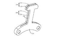
図11及び13に示すように、一連垂直ストッパーの第4の実施形態では、長手方向において、開口溝400の長さは、第1端部100の長さ、接続部300の長さ、及び、第2端部200の長さに等しい;垂直方向において、開口溝400は、第1端部100、接続部300、及び第2端部200を貫通する。このようにして、開口溝400は、第1端部100を同じ形状の第1端部第1層110と第1端部第2層120に分割し、接続部300を同じ形状の接続部第1層310と接続部第2層320に分割し、第2端部200を同じ形状の第2端部第1層210と第2端部第2層220に分割する。第1の一連垂直ストッパー上の開口溝400の異なる位置によれば、第1端部第1層110及び第1端部第2層120、接続部第1層310及び接続部第2層320、及び第2端第1層210及び第2端第2層220の厚さが同じかまたは異なる。このようにして、一連垂直ストッパーの1次固有振動数が変更され、列車の走行プロセス中に車軸ボックスとの共振を回避するのに役立つ。また、上下方向では、開口溝400が第2端200を貫通しているため、第2端200を通過する開口溝400の長さH1と第2端200の全長Hとの関係は、H1=Hである。すなわち、開口溝400は、第1の一連垂直ストッパーを、同じ形状及び構造を有する2つのラメラ構造に分割する。
As shown in FIGS. 11 and 13, in the fourth embodiment of the series vertical stopper, in the longitudinal direction, the length of the
他の実施形態では、開口溝400の数が1より大きい場合、シート層構造の数は2つに限定されず、必要に応じてそれに応じて増やすことができる。
In other embodiments, if the number of
複数のラメラで構成される一連垂直ストッパーの1次固有振動数は、一体構造の一連垂直ストッパーの固有振動数とは異なるため、列車の運転中に車軸ボックスとの共振を防ぐことができる。 The first-order natural frequency of the series of vertical stoppers composed of multiple lamellas is different from the natural frequency of the series of vertical stoppers of monolithic structure, thus preventing resonance with the axle box during train operation.
他の実施形態では、制振層410を隣接するシートの間に提供することができ、制振層410は、例えば、ガラス接着剤、ケトン構造シーラント、またはダクタイル鋳鉄などの緩衝材料で作ることができる。 これにより、一連垂直ストップの1次固有振動数が変化する可能性があり、他方では、振動エネルギーを吸収する可能性がある。
In other embodiments, a damping
以下に、本考案の高減衰を組み込んだ新高速鉄道台車の縦型ストッパーの第1シリーズの試験(ハンマー試験、以下の試験、有限要素解析を含む)を紹介する。同じ形状、材質の縦型ストッパーを参考にしている。 The following presents a first series of tests (including hammer tests, following tests, and finite element analysis) of a vertical stopper for a new high-speed rail bogie incorporating the high damping of the present invention. A vertical stopper with the same shape and material is used as a reference.
ハンマー試験方法:実験室では、C字型の固定具を使用して、一連垂直ストッパーの下端、つまり固定部分の90%をクランプして固定する。C型クランプを一連垂直ストッパーで安定した平らなテストテーブルに固定し、クランプを固定する。次に、DYTRAN加速度センサーは、DYTRAN加速度センサーの下部にある磁石とネジ穴を含む、一連垂直ストッパーの上部ヘッドの最初の端に配置される。DYTRANの下部は、次のボルトに対応し、接続に固定されている。まず、DYTRANベースを一連垂直ストッパーの最初の端の下面に強力な接着剤で固定してから、DYTRAN加速度計をベースにねじ込む。加速度センサーは、データ取得用のケーブル(信号を送信して電力を供給する)を介してDewesoftデータ復調器に接続される。最初の一連垂直ストッパーを固定し、加速度センサーを取り付けたら、インパクトハンマーを使用して最初の一連垂直ストッパーの上面を叩き、叩いた後にインパクトハンマーを取り外す。タッピングプロセス中に加速度計によって収集されたデータを10秒間収集する。一連垂直停止の固有振動数は、Dewesoftソフトウェアのスペクトル分析ソフトウェアを使用して分析されました。 Hammer test method: In the laboratory, a C-shaped fixture is used to clamp and fix the lower end of a series of vertical stoppers, ie 90% of the fixed part. Secure the C-clamp to a stable flat test table with a series of vertical stops to secure the clamp. A DYTRAN accelerometer is then placed at the first end of the upper head of a series of vertical stoppers that contain magnets and screw holes at the bottom of the DYTRAN accelerometer. The lower part of the DYTRAN corresponds to the next bolt and is fixed to the connection. First, secure the DYTRAN base to the underside of the first end of a series of vertical stoppers with strong glue, then screw the DYTRAN accelerometer onto the base. The accelerometer is connected to a Dewesoft data demodulator via a cable for data acquisition (transmits signal and provides power). After fixing the first series of vertical stoppers and installing the accelerometer, use an impact hammer to hit the top surface of the first series of vertical stoppers, remove the impact hammer after hitting. Collect the data collected by the accelerometer during the tapping process for 10 s. The natural frequencies of the series of vertical stops were analyzed using spectral analysis software from Dewesoft software.
車の次の試験方法:CRH5高速列車の3番目のトレーラーの台車の7番目の車軸に一連垂直ストッパーを取り付ける。一次垂直ストッパーは、ボルトを合わせて車軸ボックスの上の位置に固定し、通常の操作でボルトに締め付けトルクを加えて一次垂直ストッパーを固定する。一連垂直ストッパーの外面の最初の端の位置に、3方向の加速度をテストできるDYTRAN加速度計を取り付ける。 DYTRAN加速度計は、強力な接着剤を介して一連垂直ストッパーの表面に密接に接続されている。これにより、DYTRAN加速度計は、テスト中に安定した通常のデータ収集状態を維持し続けることができる。加速度センサーはケーブルに接続され(信号を送信し、電力を供給する)、ケーブルラインは列車本体の下部を通過し、ドアを介して車に導入され、車に取り付けられたDewesoftデータ復調器に接続する。Dewesoftデータ復調器をオンにすると、車外の台車のセンサーが機能してデータの収集を開始し、Dewesoftデータ復調器がデータを保存して事前に分析する。一連垂直ストッパーと加速度センサー及びその他の関連機器が設置された後、Dewesoftデータ復調器は、高速列車の走行プロセス中に一連垂直ストッパーに設置された加速度センサーからデータを収集し続ける。テストが完了したら、Dewesoftデータ復調器のデータ処理ソフトウェアを使用して収集されたデータを処理し、垂直ストッパーの固有振動数に関する一連情報を取得する。 The following test method for vehicles: Install a series of vertical stops on the 7th axle of the bogie of the 3rd trailer of the CRH5 high-speed train. The primary vertical stop is secured in position above the axle box by aligning the bolts and normal operation applies tightening torque to the bolt to secure the primary vertical stop. A DYTRAN accelerometer capable of testing acceleration in three directions is mounted at the first edge of the outer surface of the series of vertical stops. A DYTRAN accelerometer is closely attached to the surface of a series of vertical stoppers via a strong adhesive. This allows the DYTRAN accelerometer to continue to maintain a stable and normal data acquisition state during testing. The accelerometer is connected to a cable (sends a signal and provides power), the cable line passes under the train body, is introduced into the car through the door, and connects to a Dewesoft data demodulator mounted on the car. do. When the Dewesoft Data Demodulator is turned on, the sensors on the trolley outside the vehicle will work and start collecting data, which the Dewesoft Data Demodulator will store and pre-analyze. After the series of vertical stoppers and acceleration sensors and other related equipment are installed, the Dewesoft data demodulator continues to collect data from the acceleration sensors installed on the series of vertical stoppers during the running process of the high speed train. Once the test is complete, process the collected data using the Dewesoft Data Demodulator data processing software to obtain a series of information about the natural frequencies of the vertical stopper.
有限要素解析:ANSYSの有限要素解析ソフトウェアを使用して解析を実行できる。 Finite Element Analysis: Analysis can be performed using ANSYS finite element analysis software.
図14を参照すると、本考案の高減衰を内蔵した新規高速鉄道台車の一連垂直ストッパーと同じ形状・材質の既存の一連垂直ストッパー、すなわち図2に示す一連垂直ストッパーの垂直ストッパーハンマリング実験の周波数応答曲線が示されている。 図14に示すように、既存の一連垂直ストッパーの一次固有振動数は500~600Hzであり、二次固有振動数は約1200Hzである。 Referring to FIG. 14, the frequency of the vertical stopper hammering experiment of the existing vertical stopper series with the same shape and material as the new high-speed rail bogie with built-in high damping of the present invention, that is, the vertical stopper series shown in FIG. Response curves are shown. As shown in FIG. 14, the existing series of vertical stoppers has a primary natural frequency of 500-600 Hz and a secondary natural frequency of about 1200 Hz.
図15を参照すると、図2に示されている既存の一連垂直ストッパーの車両のフォローテスト周波数応答曲線が示されている。 上記の試験方法に基づく車両によると、図に示す既存の垂直ストッパーを備えたCRH5高速列車(3両7軸のCRH5列車に搭載)の1700キロメートルの鉄道路線で、18日に渡る往復で9回試験された。図15に示すように、既存の一連垂直ストッパーの1次固有振動数は500Hzを超えている。 Referring to FIG. 15, there is shown a follow-test frequency response curve for a vehicle of the existing series of vertical stops shown in FIG. According to the vehicle based on the above test method, 9 round trips over 18 days on 1700 km railway line of CRH5 high-speed train (installed in 3-car 7-axle CRH5 train) with existing vertical stopper shown in the figure. tested. As shown in Fig. 15, the first-order natural frequency of the existing series of vertical stoppers exceeds 500Hz.
図16を参照すると、図2に示す既存の一連垂直ストッパーの有限要素解析によって得られた最初の2つの最大モードが示されている。ここで、材料はS335タイプの低炭素鋼、密度は7850kg/m3、Poisson The比は0.3、弾性率は206GPa、降伏強度は335MPaである。図16に示すように、既存の一連垂直ストッパーの1次固有振動数は555.6 Hz、2次固有振動数は1284Hzである。 Referring to FIG. 16, the first two maximum modes obtained by finite element analysis of the existing series of vertical stoppers shown in FIG. 2 are shown. Here, the material is S335 type low carbon steel, the density is 7850 kg/m3, the Poisson The ratio is 0.3, the modulus is 206 GPa and the yield strength is 335 MPa. As shown in Figure 16, the existing series of vertical stoppers has a primary natural frequency of 555.6 Hz and a secondary natural frequency of 1284 Hz.
要約すると、本考案の高減衰を内蔵した高速鉄道列車台車の1級縦型ストッパーと同じ形状・材質の既存一連縦型ストッパーの1次固有振動数は次のようになる。 555.6 Hz、2次固有振動数は555.6Hzである。周波数は1284Hzである。 In summary, the primary natural frequency of the existing series of vertical stoppers of the same shape and material as the class 1 vertical stopper of the high-damping high-speed railway bogie of the present invention is as follows. 555.6 Hz, second natural frequency is 555.6 Hz. The frequency is 1284Hz.
図17を参照すると、本考案の高減衰を内蔵した新しい高速鉄道車両台車の第1の垂直ストッパーの第1実施形態の打撃実験の周波数応答曲線が示されている。図17に示すように、ストッパーの第1実施形態の一次固有周波数は約340Hzである。 Referring to FIG. 17, there is shown the frequency response curve of the impact experiment of the first embodiment of the first vertical stopper of the new high-speed rail vehicle bogie with built-in high damping of the present invention. As shown in FIG. 17, the primary natural frequency of the first embodiment of the stopper is approximately 340 Hz.
図18を参照すると、これは、高減衰が組み込まれた新しい高速鉄道列車台車の一連垂直ストッパーの第1実施形態の有限要素解析によって得られた第1の2次最大モードを示している。減衰層を効果的にシミュレートするために、メッシュサイズは0.5mm、合計で241万個の要素があり、金属層密度は7850kg/m3、弾性率は206GPa、ポアソン比は0.3、減衰層密度は1420kg/m3、弾性率は3MPa、比は0.45である。境界条件:下部に2つのボルト穴を固定する。 図18に示すように、本考案の垂直ストッパーの第1実施形態の一次固有振動数は約345.42Hzであり、二次固有振動数は約1283.16Hzである。 Referring to FIG. 18, this shows the first 2nd order maximum mode obtained by finite element analysis of the first embodiment of the new high-speed rail train bogie series vertical stopper with built-in high damping. To effectively simulate the damping layer, the mesh size is 0.5 mm, there are a total of 2.41 million elements, the metal layer density is 7850 kg/m3, the elastic modulus is 206 GPa, the Poisson's ratio is 0.3, and the damping layer density is 1420 kg/m3, elastic modulus 3 MPa, ratio 0.45. Boundary conditions: Fix two bolt holes at the bottom. As shown in FIG. 18, the first embodiment of the vertical stopper of the present invention has a primary natural frequency of about 345.42 Hz and a secondary natural frequency of about 1283.16 Hz.
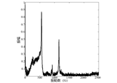
図19を参照すると、本考案の高減衰を内蔵した新しいタイプの高速鉄道列車台車の第4の実施形態のハンマー実験の周波数応答曲線を示している。図19に示すように、本考案の一連垂直ストッパーの第4の実施形態の1次固有振動数は280Hzであり、2次固有振動数は1200Hzである。 Referring to FIG. 19, it shows the frequency response curve of the hammer experiment of the fourth embodiment of the new type high-speed rail train bogie with built-in high damping of the present invention. As shown in FIG. 19, the fourth embodiment of the series of vertical stoppers of the present invention has a primary natural frequency of 280 Hz and a secondary natural frequency of 1200 Hz.
図20を参照すると、本考案の一連垂直ストッパーの第4の実施形態の試験後の車両の周波数応答曲線が示されている;上記の試験方法に従う車両によれば、図11に示される一連垂直ストッパーへのCRH5高速列車(3両7車軸のCRH5列車に設置)が、60キロメートルを超える鉄道路線を15時間で5回往復した。 図20に示すように、本考案による一連垂直ストッパーの第4の実施形態の1次固有振動数は約210Hzであり、2次固有振動数は約1100~1200Hzである。 Referring to FIG. 20, there is shown a vehicle frequency response curve after testing of the fourth embodiment of the series vertical stopper of the present invention; A CRH5 high-speed train to Stopper (installed in a 3-car 7-axle CRH5 train) made 5 round trips over 60 kilometers of railway lines in 15 hours. As shown in FIG. 20, the fourth embodiment of the series vertical stopper according to the present invention has a primary natural frequency of about 210 Hz and a secondary natural frequency of about 1100-1200 Hz.
図21を参照すると、本考案の高減衰が組み込まれた新規の高速鉄道列車台車一次垂直ストッパーの第4の実施形態の有限要素解析によって得られた最初の2つの最大モードを示す。図21に示すように、本考案の一連垂直ストッパーの第4の実施形態の1次固有振動数は約2863.36Hzであり、2次固有振動数は約1292.33Hzである。 Referring to FIG. 21, the first two maximum modes obtained by finite element analysis of the fourth embodiment of the novel high-damping integrated high-damping high-speed rail bogie primary vertical stopper of the present invention are shown. As shown in FIG. 21, the fourth embodiment of the series of vertical stoppers of the present invention has a primary natural frequency of about 2863.36 Hz and a secondary natural frequency of about 1292.33 Hz.
要約すると、本考案の各実施形態における一連垂直ストッパーは、それが一次固有振動数であろうと二次固有振動数であろうと、既存の一連垂直ストッパーとは異なり、それによって、台車の車軸ボックスの固有振動数の値とはかなり異なるため、一連垂直ストッパーが列車の台車の車軸ボックスと共振するのを防ぐことができる。 同時に、開口部に制振層を配置することで振動エネルギーを吸収できるため、列車の通常運転時の振動エネルギーを低減し、第1シリーズの縦型ストッパーの耐用年数をさらに延ばすことができる。 In summary, the series of vertical stops in each embodiment of the present invention, whether it is the primary natural frequency or the secondary natural frequency, is different from the existing series of vertical stops, thereby reducing the load on the axle box of the truck. A series of vertical stops can be prevented from resonating with the axle boxes of the train bogies, since they are significantly different from the natural frequency values. At the same time, the vibration energy can be absorbed by placing a damping layer in the opening, which can reduce the vibration energy during normal operation of the train and further extend the service life of the first series vertical stopper.
本考案は上記の例に限定されない。当業者は、上記の説明に従って改善や置換を加えることができ、これらの改善及び置換はすべて本考案の添付の実用新案登録請求の範囲の保護範囲に含まれることを理解されたい。 The invention is not limited to the above examples. It should be understood that those skilled in the art can make improvements and replacements according to the above description, and all these improvements and replacements are included in the protection scope of the attached utility model claims of the present invention.
Claims (10)
第1端部、第2端部、接続部、開口溝を含み、
前記第1端部は台車と協調し、縦方向に平行に伸び、
前記第2端部は高速鉄道列車の車軸ボックスに接続され、縦方向に平行に伸び、
前記接続部は第1端部と第2端部を接続し、垂直方向に平行であり、「工」字形一連垂直ストッパーを形成し、
前記開口溝は一連垂直ストッパーの固有振動数を変更するために、材料を除去する方法で一連垂直ストッパーに形成される
ことを特徴とする高速鉄道列車の台車用一連垂直ストッパー。 The direction of gravitational acceleration is defined as the vertical direction, and the direction of travel of high-speed rail is defined as the vertical direction,
including a first end, a second end, a connecting portion, an open groove,
said first end cooperating with the carriage and extending parallel to the longitudinal direction;
said second end being connected to an axle box of a high speed rail train and extending parallel to the longitudinal direction;
the connecting portion connects the first end and the second end, is parallel to the vertical direction, and forms a series of vertical stops in the shape of a Chinese character;
A string of vertical stoppers for bogies of high-speed trains, characterized in that said open grooves are formed in the string of vertical stoppers by means of material removal to change the natural frequency of the string of vertical stoppers.

Priority Applications (1)
| Application Number | Priority Date | Filing Date | Title |
|---|---|---|---|
| JP2022002494U JP3239237U (en) | 2022-07-28 | 2022-07-28 | Series of vertical stoppers for high-speed train bogies |
Applications Claiming Priority (1)
| Application Number | Priority Date | Filing Date | Title |
|---|---|---|---|
| JP2022002494U JP3239237U (en) | 2022-07-28 | 2022-07-28 | Series of vertical stoppers for high-speed train bogies |
Publications (1)
| Publication Number | Publication Date |
|---|---|
| JP3239237U true JP3239237U (en) | 2022-09-27 |
Family
ID=83398834
Family Applications (1)
| Application Number | Title | Priority Date | Filing Date |
|---|---|---|---|
| JP2022002494U Active JP3239237U (en) | 2022-07-28 | 2022-07-28 | Series of vertical stoppers for high-speed train bogies |
Country Status (1)
| Country | Link |
|---|---|
| JP (1) | JP3239237U (en) |
-
2022
- 2022-07-28 JP JP2022002494U patent/JP3239237U/en active Active
Similar Documents
| Publication | Publication Date | Title |
|---|---|---|
| CN112519820B (en) | Bogie system of railway vehicle and railway vehicle | |
| CN102051843B (en) | High-speed railway noise barrier | |
| CN104554324B (en) | A kind of monoblock type framework and bogie | |
| CN101413233A (en) | Method and device for designing shock and vibration absorption type steel rail suspending fastener | |
| CN202380369U (en) | Multi-directional vibration reduction fastener of steel track | |
| CN112519821A (en) | Bogie cabin for railway vehicle and bogie system | |
| Zhao et al. | Internal noise reduction in railway vehicles by means of rail grinding and rail dampers | |
| CN104389247B (en) | Be applicable to powered shock absorption device and the F rail structure of medium-and low-speed maglev car F rail | |
| CN113696925B (en) | Bogie assembly and rail vehicle | |
| CN103790080B (en) | City rail wheel guard rail device and installation method thereof | |
| WO2022052652A1 (en) | Bogie and locomotive having same | |
| JP3239237U (en) | Series of vertical stoppers for high-speed train bogies | |
| CN113696927A (en) | Rail vehicle | |
| CN113696929A (en) | Bogie assembly and rail vehicle | |
| CN203593001U (en) | High-speed railway wagon bogie | |
| CN113696926A (en) | Bogie side cabin plate assembly, bogie and railway vehicle | |
| CN205930746U (en) | Steering frame | |
| KR101236535B1 (en) | Monorail bogie assay with yawing preventing means | |
| CN111749056A (en) | Comprehensive damping vibration-damping noise-reducing device for mass-distributed steel rail | |
| CN216269264U (en) | Bogie assembly and rail vehicle | |
| CN101451584A (en) | Damping device of screw compression spring for rail vehicle and installation method thereof | |
| CN113799833B (en) | Bogie bilge plate assembly, bogie and railway vehicle | |
| KR101229285B1 (en) | Scaled bogie for railway vehicle simulator using a similarity method | |
| CN201095369Y (en) | Inclined wedge for bogie | |
| WO2023082673A1 (en) | Elastic suspended mounting structure for heavy-duty apparatus under rail vehicle |
Legal Events
| Date | Code | Title | Description |
|---|---|---|---|
| R150 | Certificate of patent or registration of utility model |
Ref document number: 3239237 Country of ref document: JP Free format text: JAPANESE INTERMEDIATE CODE: R150 |