JP3224680U6 - Cleaning wipes - Google Patents
Cleaning wipes Download PDFInfo
- Publication number
- JP3224680U6 JP3224680U6 JP2019003272U JP2019003272U JP3224680U6 JP 3224680 U6 JP3224680 U6 JP 3224680U6 JP 2019003272 U JP2019003272 U JP 2019003272U JP 2019003272 U JP2019003272 U JP 2019003272U JP 3224680 U6 JP3224680 U6 JP 3224680U6
- Authority
- JP
- Japan
- Prior art keywords
- cleaning
- grip handle
- water
- shaft portion
- brush head
- Prior art date
- Legal status (The legal status is an assumption and is not a legal conclusion. Google has not performed a legal analysis and makes no representation as to the accuracy of the status listed.)
- Expired - Fee Related
Links
- 238000004140 cleaning Methods 0.000 title claims abstract description 82
- XLYOFNOQVPJJNP-UHFFFAOYSA-N water Substances O XLYOFNOQVPJJNP-UHFFFAOYSA-N 0.000 claims abstract description 92
- 239000000835 fiber Substances 0.000 claims abstract description 32
- 239000004372 Polyvinyl alcohol Substances 0.000 claims abstract description 14
- 229920002451 polyvinyl alcohol Polymers 0.000 claims abstract description 14
- 229920005989 resin Polymers 0.000 claims abstract description 8
- 239000011347 resin Substances 0.000 claims abstract description 8
- 239000004743 Polypropylene Substances 0.000 claims abstract description 7
- 229920001155 polypropylene Polymers 0.000 claims abstract description 7
- 238000002788 crimping Methods 0.000 claims abstract description 4
- -1 polypropylene Polymers 0.000 claims abstract description 4
- 238000010521 absorption reaction Methods 0.000 claims description 13
- 230000003014 reinforcing effect Effects 0.000 claims description 6
- 238000004049 embossing Methods 0.000 claims description 5
- 238000005520 cutting process Methods 0.000 claims description 4
- 239000004744 fabric Substances 0.000 abstract description 5
- 230000003247 decreasing effect Effects 0.000 abstract description 2
- 238000010586 diagram Methods 0.000 abstract 1
- 239000000463 material Substances 0.000 description 6
- 239000011162 core material Substances 0.000 description 5
- 230000002745 absorbent Effects 0.000 description 4
- 239000002250 absorbent Substances 0.000 description 4
- 229920003023 plastic Polymers 0.000 description 3
- 239000004033 plastic Substances 0.000 description 3
- 238000005406 washing Methods 0.000 description 3
- 239000003599 detergent Substances 0.000 description 2
- 238000005187 foaming Methods 0.000 description 2
- 239000011148 porous material Substances 0.000 description 2
- 239000000919 ceramic Substances 0.000 description 1
- 239000011521 glass Substances 0.000 description 1
- 230000037431 insertion Effects 0.000 description 1
- 238000003780 insertion Methods 0.000 description 1
- 238000005096 rolling process Methods 0.000 description 1
- 229910001220 stainless steel Inorganic materials 0.000 description 1
- 239000010935 stainless steel Substances 0.000 description 1
- 238000003860 storage Methods 0.000 description 1
- 239000000725 suspension Substances 0.000 description 1
- 229920005992 thermoplastic resin Polymers 0.000 description 1
Images


Abstract
【課題】深底のボトルや水筒などを楽に洗浄することができ、洗浄後に残っている水滴を、布巾や吸水紙を別途に用いることなく、直ちに拭き取ることのできる洗浄拭き取り具を提供する。
【解決手段】掴み柄10と、掴み柄10の一方側端部に着脱可能に設けた吸水用ブラシヘッド60と、掴み柄10の他方側端部に着脱可能に設けた洗浄用ブラシヘッド70と、を有する。吸水用ブラシヘッド60がポリビニルアルコール樹脂製の吸水体61を有し、洗浄用ブラシヘッド70がポリプロピレン繊維を捲縮させてなる繊維集合体71を有する。掴み柄10の長さを増減することができる。
【選択図】図1An object of the present invention is to provide a cleaning wiping tool capable of easily cleaning a deep-bottom bottle, a water bottle, or the like, and immediately wiping water droplets remaining after cleaning without using a cloth or water-absorbing paper.
A grip handle, a water-absorbing brush head removably provided at one end of the grip handle, and a cleaning brush head removably provided at the other end of the grip handle. And The water-absorbing brush head 60 has a water-absorbing body 61 made of polyvinyl alcohol resin, and the cleaning brush head 70 has a fiber assembly 71 formed by crimping polypropylene fibers. The length of the handle 10 can be increased or decreased.
[Selection diagram] Fig. 1
Description
本考案は、洗浄拭き取り具、詳しくは、ボトルや水筒などを洗浄したり洗浄後に水滴を拭き取ったりすることに用いられる洗浄拭き取り具に関する。 The present invention relates to a cleaning wiping tool, and more particularly to a cleaning wiping tool used for cleaning bottles, water bottles and the like and for wiping off water droplets after cleaning.
従来より、柄の一端にスポンジや毛束などのブラシを装着してなる洗浄用ブラシは広く知られ、一般家庭や各種作業場などの多くの場所で汎用されている。従来例としてのこの種の洗浄用ブラシは、作業者が片手で柄を掴んでボトルや水筒などの内面をブラシで擦って洗浄するという使い方をするのが一般的である。そして、洗浄し終わったボトルや水筒などの物品は、表面や内面に付着している水滴を手作業で布巾や吸水紙などを使用して拭き取ったり自然乾燥させたりする、ということが行われている。 2. Description of the Related Art Conventionally, a cleaning brush in which a brush such as a sponge or a hair bundle is attached to one end of a handle is widely known, and is widely used in many places such as ordinary households and various workplaces. This type of cleaning brush as a conventional example is generally used in such a manner that an operator grasps a handle with one hand and rubs the inner surface of a bottle, a water bottle or the like with a brush for cleaning. After washing, bottles and water bottles are used to wipe off water droplets adhering to the surface or inner surface by hand using a cloth or water-absorbing paper, etc., and let them dry naturally. I have.
先行例によると、紐状体の一端にブラシを連結した洗浄用ブラシが提案されている(特許文献1参照)。この特許文献1に記載されている洗浄用ブラシによると、瓶などの容器の中に入れたブラシを転動させることによって汚れが除去される、とされている。 According to a prior example, a cleaning brush in which a brush is connected to one end of a cord-like body has been proposed (see Patent Document 1). According to the cleaning brush described in Patent Literature 1, dirt is removed by rolling a brush placed in a container such as a bottle.
また、他の先行例によると、略円柱状の基部の一端にペットボトルキャップの内側を洗浄するための毛束を設け、もう一端に、ペットボトル口部内側を洗浄するスポンジとペットボトル口部ネジ部を洗浄する毛束を内側に向けて設けたペットボトル洗浄ブラシが提案されている(特許文献2参照)。 According to another prior art example, a bristle bundle for cleaning the inside of a plastic bottle cap is provided at one end of a substantially cylindrical base, and a sponge and a plastic bottle mouth for cleaning the inside of the plastic bottle mouth are provided at the other end. There has been proposed a PET bottle cleaning brush provided with a hair bundle for cleaning a screw portion facing inward (see Patent Document 2).
ところで、洗浄し終わったボトルや水筒などの物品に付着している水滴を布巾や吸水紙を使用して手作業で拭き取る作業は煩わしく、特に深底のボトルや水筒などでは内底部分に手が入りにくかったり入らなかったりすることも多いという問題があった。上掲の先行例に係る洗浄ブラシを用いて洗浄した物品についても同様の問題が生じる。 By the way, it is troublesome to manually wipe off water droplets adhering to items such as bottles and water bottles that have been washed with a cloth or absorbent paper. There was a problem that it was difficult or difficult to enter. The same problem occurs with articles cleaned using the cleaning brush according to the above-mentioned prior example.
本考案は以上の問題点を改善することを意図してなされたものであり、深底のボトルや水筒などの物品を楽に洗浄することができることは勿論、洗浄した物品に残っている水滴を、布巾や吸水紙を別途に用いることなく、洗浄後に直ちに拭き取ることのできる洗浄拭き取り具を提供することを目的としている。 The present invention has been made with the intention of improving the above problems, and it is possible to easily wash articles such as deep-bottom bottles and water bottles, as well as to remove water droplets remaining on the washed articles, An object of the present invention is to provide a cleaning wiping tool that can be wiped immediately after cleaning without separately using a cloth or absorbent paper.
本考案に係る洗浄拭き取り具は、手作業による洗浄及び水滴の拭き取りに用いる洗浄拭き取り具であって、棒状の掴み柄と、水滴の拭き取りに用いられる吸水用ブラシヘッドと、洗浄に用いられる洗浄用ブラシヘッドと、を有し、上記吸水用ブラシヘッドと上記洗浄用ブラシヘッドとが、上記掴み柄の一方側及び他方側の各端部に振り分けて各別に設けられている、というものである。 The cleaning wiping tool according to the present invention is a cleaning wiping tool used for manual cleaning and wiping of water droplets, and includes a rod-shaped grip handle, a water absorbing brush head used for wiping water droplets, and a cleaning wiping device used for cleaning. A brush head, wherein the water-absorbing brush head and the cleaning brush head are separately provided separately on one end and the other end of the grip handle.
このように構成された洗浄拭き取り具によれば、作業者が掴み柄を片手で掴んだまま、洗浄用ブラシヘッドと吸水用ブラシヘッドとを使い分けて、物品の洗浄と洗浄した物品に付着している水滴の拭き取りとを行うことが可能である。特に、掴み柄を片手で掴んで、吸水用ブラシヘッドを深底のボトルや水筒などの物品に差し込んで水滴の拭き取りを楽に行うことができるという利便性がある。 According to the cleaning wiping tool configured as described above, while the operator holds the grip handle with one hand, the cleaning brush head and the water absorption brush head are selectively used, and the cleaning brush head is attached to the cleaned article and the cleaned article. It is possible to wipe off water drops that are present. In particular, there is the convenience that the gripping handle can be gripped with one hand and the water absorbing brush head can be inserted into an article such as a deep-bottomed bottle or water bottle to easily wipe off water drops.
本考案では、上記吸水用ブラシヘッドが、ポリビニルアルコール樹脂のスポンジシートを切り開くことによって形成された多数の枝分かれ細片を有する吸水体と、この吸水体が着脱される第1保持部を有して上記掴み柄の端部に着脱可能な第1取付具と、を備え、上記掴み柄に装着された第1取付具の上記第1保持部による吸水体の保持位置が、上記掴み柄の軸線に対する偏り箇所になるように構成されていることが望ましい。ポリビニルアルコール樹脂(PVA)は 親水性が非常に強い熱可塑性樹脂であり、PVAスポンジシートはそれ自体に備わっている微細な連続気孔が水滴をすばやく吸収する、という超速吸水性を発揮する。この超速吸水性という特性は、PVAのスポンジシートを切り開くことによって形成された多数の枝分かれ細片を有する吸水体によっても当然に発揮されるので、吸水用ブラシヘッドを用いて洗浄後の物品に付着している水滴を拭き取る際にもこの特性が生かされる。また、吸水したPVAのスポンジシートを絞ると吸水性が回復するという特性を水滴の拭き取りに利用することも可能である。さらに、掴み柄に対する第1取付具の着脱性や第1取付具に対する吸水体の着脱性を利用することによって、吸水用ブラシヘッド全体の取り換えや吸水体の取り換えも可能である。そのほか、吸水体の保持位置が、掴み柄の軸線に対する偏り箇所になるように構成されていることによって使い勝手が向上する。 In the present invention, the water absorbing brush head has a water absorbing body having a large number of branched strips formed by cutting out a sponge sheet of polyvinyl alcohol resin, and a first holding portion to which the water absorbing body is attached and detached. A first attachment that can be attached to and detached from the end of the grip handle, and wherein the holding position of the water absorbing body by the first holding portion of the first attachment mounted on the grip handle is relative to the axis of the grip handle. It is desirable to be configured so as to be a biased portion. Polyvinyl alcohol resin (PVA) is a thermoplastic resin having extremely strong hydrophilicity, and the PVA sponge sheet exhibits ultra-fast water absorption, in which fine continuous pores provided in itself absorb water droplets quickly. The property of super-high-speed water absorption is naturally exerted by a water-absorbing body having a large number of branched strips formed by cutting a sponge sheet of PVA. This property can also be used when wiping water drops. In addition, it is also possible to use the property that water absorption is recovered by squeezing a sponge sheet of PVA that has absorbed water, for wiping water droplets. Furthermore, by utilizing the detachability of the first mounting tool with respect to the grip handle and the detachability of the water absorbing body with respect to the first mounting tool, replacement of the entire water absorbing brush head and replacement of the water absorbing body are also possible. In addition, the usability is improved because the holding position of the water absorbing body is configured to be a position deviated from the axis of the grip handle.
本考案において、上記枝分かれ細片は、内層部に埋入された補強用芯材を有し、かつ、外面にエンボス加工により形成された凹凸を有する、という構成を有することが望ましい。この構成において、枝分かれ細片の外面にエンボス加工により形成された凹凸は、水滴を効率よく吸収させることに役立つ。また、枝分かれ細片の内層部に埋入された補強用芯材は、吸水体の耐久性を向上させることに役立つ。 In the present invention, it is preferable that the branched strip has a configuration in which the branching strip has a reinforcing core material embedded in an inner layer portion and has irregularities formed by embossing on an outer surface. In this configuration, the unevenness formed by embossing on the outer surface of the branch strip helps to efficiently absorb water droplets. Further, the reinforcing core material embedded in the inner layer portion of the branched strip helps to improve the durability of the water absorbent.
本考案では、上記洗浄用ブラシヘッドが、ポリプロピレン繊維を捲縮させてなる繊維集合体と、この繊維集合体が着脱される第2保持部を有して上記掴み柄の端部に着脱可能な第2取付具と、を備え、上記掴み柄に装着された第2取付具の上記第2保持部による繊維集合体の保持位置が、上記掴み柄の軸線に対する偏り箇所になるように構成されていることが望ましい。ポリプロピレン(PP)繊維を捲縮させてなる繊維集合体は洗剤の泡立ちをよくして洗浄効率を高めることに役立つ。そのほか、繊維集合体の保持位置が、掴み柄の軸線に対する偏り箇所になるように構成されていることによって使い勝手が向上する。 In the present invention, the cleaning brush head has a fiber assembly formed by crimping polypropylene fibers, and a second holding portion to which the fiber assembly is attached and detached, and is detachably attached to an end of the grip handle. And a second mounting member, wherein the holding position of the fiber assembly by the second holding portion of the second mounting member mounted on the grip handle is a position deviated from the axis of the grip handle. Is desirable. The fiber aggregate formed by crimping the polypropylene (PP) fiber is useful for improving the foaming of the detergent and increasing the cleaning efficiency. In addition, usability is improved because the holding position of the fiber assembly is configured to be a location deviated from the axis of the grip handle.
本考案では、上記掴み柄が、補助掴み柄として使用可能な第1軸部と補助掴み柄として使用可能な第2軸部とに分かれていて、第1軸部及び第2軸部のうちの少なくとも一方側部材が筒状に形成され、かつ、筒状の一方側部材に他方側部材が抜き差し自在に差し込まれ、上記一方側部材の先端部が上記掴み柄の一方側の端部に相応し、この一方側部材から突出した他方側部材の先端部が上記掴み柄の他方側の端部に相応していると共に、上記一方側部材とこれに差し込まれた上記他方側部材とを一体化するための固定機構を有する、という構成を採用することができる。これによれば、一方側部材から他方側部材引き抜いてそれらの各部材を補助掴み柄として利用することにより、洗浄用ブラシヘッドを利用する洗浄と吸水用ブラシヘッドを利用する水滴の拭き取りとを行うことができる。 In the present invention, the grip handle is divided into a first shaft portion that can be used as an auxiliary grip handle and a second shaft portion that can be used as an auxiliary grip handle, and of the first shaft portion and the second shaft portion. At least one side member is formed in a cylindrical shape, and the other side member is removably inserted into the cylindrical one side member, and the tip of the one side member corresponds to the one end of the grip handle. The tip of the other member protruding from the one member corresponds to the other end of the grip handle, and integrates the one member with the other member inserted therein. Having a fixing mechanism for the above. According to this, by using the brush members for cleaning and wiping off water droplets using the brush head for water absorption, by pulling out the other member from the one-side member and using those members as auxiliary gripping handles. be able to.
本考案では、上記固定機構が、上記第1軸部又は上記第2軸部のうちの一方側部材に設けられた凹部と、他方側部材に形成された弾性片に設けられて上記一方側部材に対する上記他方側部材の抜き差し動作を通じて上記凹部に嵌脱される凸部とを有してなり、上記凹部が上記一方側部材の軸方向複数箇所に間隔を隔てて設けられているか、又は、上記凸部が上記他方側部材の軸方向複数箇所に間隔を隔てて設けられている、という構成を採用することが可能である。これによれば、第1軸部とこれに差し込まれた第2軸部とによって構成される棒状の掴み柄の長さを段階的に増減調節することができるようになるという利便性が得られる。 In the present invention, the fixing mechanism is provided on a concave portion provided on one side member of the first shaft portion or the second shaft portion and on an elastic piece formed on the other side member, and the one side member is provided. And a convex portion that is fitted into and disengaged from the concave portion through the insertion / removal operation of the other side member, and the concave portion is provided at a plurality of axial positions of the one side member at intervals, or It is possible to adopt a configuration in which the protrusions are provided at a plurality of positions in the axial direction of the other side member at intervals. According to this, it is possible to obtain the convenience that the length of the bar-shaped grip formed by the first shaft portion and the second shaft portion inserted therein can be gradually increased or decreased. .
本考案では、棒状の上記掴み柄と上記第1軸部と上記第2軸部とのそれぞれに、吊り下げ用の孔部が具備されていることが望ましい。これによれば、棒状の掴み柄の一方側及び他方側の各端部に振り分けて各別に設けられている吸水用ブラシヘッドや洗浄用ブラシヘッドを乾燥させるときに、掴み柄に具備された吊り下げ用の孔部を利用することができ、また、第1軸部や第2軸部に各別に設けられた吸水用ブラシヘッドや洗浄用ブラシヘッドを個別に乾燥させるときに、第1軸部や第2軸部に具備された吊り下げ用の孔部を利用することができる。 In the present invention, it is preferable that each of the rod-shaped grip handle, the first shaft portion, and the second shaft portion has a hanging hole. According to this, when the water-absorbing brush head and the cleaning brush head provided separately to one end and the other end of the rod-shaped grip handle are dried, the suspension provided on the grip handle is provided. A lowering hole can be used, and when the water-absorbing brush head and the cleaning brush head separately provided on the first shaft portion and the second shaft portion are individually dried, the first shaft portion is used. Alternatively, a hanging hole provided in the second shaft portion can be used.
本考案に係る洗浄拭き取り具によれば、ボトルや水筒などの深底の物品を楽に洗浄することができることは勿論、洗浄した物品に残っている水滴を、布巾や吸水紙を別途に用いることなく、洗浄後に直ちに楽に拭き取ることが可能である。また、たとえば1人の作業者が掴み柄を片手で掴んだまま物品を洗浄したり水滴を拭き取ったりすることができるだけでなく、1つの洗浄拭き取り具を利用して、2人の作業者が洗浄と水滴の拭き取りとを分担して行うことも可能になるという利便性がある。 According to the cleaning and wiping device according to the present invention, it is possible to easily clean deep-bottom articles such as bottles and water bottles, as well as to remove water droplets remaining on the washed articles without using a cloth or absorbent paper separately. It can be easily wiped off immediately after washing. In addition, for example, not only can one worker clean the articles or wipe off water drops while holding the grip handle with one hand, but also two workers can use one cleaning wiping tool to clean the articles. And the wiping of the water droplets.
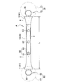
図1は本考案の実施形態に係る洗浄拭き取り具Aの正面図、図2は図1のII−II線に沿う断面図である。また、図3は図1の洗浄拭き取り具Aの背面図、図4は図1の洗浄拭き取り具Aの側面図である。 FIG. 1 is a front view of a cleaning wiping tool A according to an embodiment of the present invention, and FIG. 2 is a cross-sectional view taken along the line II-II of FIG. 3 is a rear view of the cleaning wiping tool A of FIG. 1, and FIG. 4 is a side view of the cleaning wiping tool A of FIG.
洗浄拭き取り具Aの使用対象には、ガラス製やステンレス製のボトル、水筒、コップや、陶磁器、フッ素樹脂加工品、パイプ材などの工業品といった多種類の物品が含まれる。図例の洗浄拭き取り具Aは、まっすぐな棒状の掴み柄10と、水滴の拭き取りに用いられる吸水用ブラシヘッド60と、洗浄に用いられる洗浄用ブラシヘッド70と、を有する。そして、吸水用ブラシヘッド60が掴み柄10の一方側の端部11に設けられているのに対して、洗浄用ブラシヘッド70が掴み柄10の他方側の端部12に設けられている。また、吸水用ブラシヘッド60が、後述する吸水体61と第1取付具65とを有し、洗浄用ブラシヘッド70が、後述する繊維集合体71と第2取付具75とを有する。
The objects to be used by the cleaning and wiping tool A include various types of articles such as glass and stainless steel bottles, water bottles, cups, and industrial products such as ceramics, fluororesin products, and pipe materials. The cleaning wiping tool A in the illustrated example has a straight rod-shaped grip handle 10, a water absorbing
この洗浄拭き取り具Aによれば、作業者が棒状の掴み柄10を片手で掴んだまま、洗浄用ブラシヘッド70と吸水用ブラシヘッド60とを使い分けて、物品の洗浄と洗浄した物品に付着している水滴の拭き取りとを行うことが可能である。特に、深底のボトルや水筒などの内部の洗浄や水滴の拭き取りを行うときには、掴み柄10を片手で掴んで洗浄用ブラシヘッド70や吸水用ブラシヘッド60を深底のボトルや水筒などの物品に差し込むことができるので、洗浄作業や拭き取り作業を楽に行うことができる。また、掴み柄10の表面には滑り止め処理が施された領域Zが備わっていることにより、作業者が洗浄や拭き取りの作業中に手を滑らせて洗浄拭き取り具Aを落としてしまうという事態を起こしにくい。
According to the cleaning wiping tool A, while the operator holds the rod-shaped grip handle 10 with one hand, the cleaning
図3に示したように、掴み柄10の一方側の端部11の背面側部分には、吊り下げ用の孔部15を備えた吊下げ片13の基部14が揺動可能に取り付けられている。したがって、同図に仮想線で示したように、掴み柄10の側方へ揺動させた吊下げ片13の孔部15を利用して吊り下げることにより、洗浄拭き取り具Aを乾燥させたりを保管したりすることができる。なお、符号16は、上記吊下げ片13を掴み柄10の背面との重なり位置(収納位置)に保持させるための位置決め突起である。
As shown in FIG. 3, a
上記した洗浄拭き取り具Aの掴み柄10は、図2に示されている筒状の第1軸部20と、この第1軸部20に抜き差し自在に差し込まれた第2軸部40とに分かれている。言い換えると、第1軸部20に第2軸部40を差し込むことによって上記掴み柄10が構成されていて、掴み柄10の表面に施されている上記した滑り止め処理の施された領域Zは第1軸部20に形成されている。また、上記吊下げ片13も第1軸部20に設けられている。そして、図1などに示したように、第1軸部20の先端部21が、上記した掴み柄10の一方側の端部11に相応し、この第1軸部20から突出した第2軸部40の先端部41が、上記した掴み柄10の他方側の端部12に相応している。
The grip handle 10 of the cleaning and wiping tool A is divided into a cylindrical
図5は第1軸部20の正面図、図6は第1軸部20の背面図、図7は第1軸部20と第1取付具65とを示した分解背面図である。
5 is a front view of the
第1軸部20の先端部21に、図7に示した第1取付具65が装着されている。第1取付具65は、この第1取付具65自体にU字形の切り目を形成することによって具備された樹脂製の弾性片66を有し、この弾性片66の自由端部に突起67が備わっているのに対して、第1軸部20の先端部21の背面側には係合孔22が備わっている。そして、第1取付具65を第1軸部20の先端部21に押し込むと、図6のように突起67が係合孔22に嵌入状に係合して第1軸部20の先端部21に第1取付具65が装着されるようになっている。したがって、第1軸部20の先端部21に装着されている第1取付具65は、突起67を押し込んで係合孔22から離脱させた上で第1軸部20の先端部21から引き抜くことによって第1軸部20から取り外される。また、第1取付具65にはリング状に形成された第1保持部68が一体に備わっていて、この第1保持部68に吸水体61が装着されている。
The
図5又は図6のように先端部21に第1取付具65を介して吸水体61が装着された第1軸部20は、補助掴み柄としての使用することができる。このため、補助掴み柄としての第1軸部20を作業者が片手で掴み、吸水体61を使ってボトルなどに付着している水滴を楽に拭き取ることが可能である。また、図6のように、第1軸部20の基端部23の背面側に吊り下げ用の孔部24が設けられていて、この孔部24を利用することにより、使用後の湿った吸水体61を下位にして吊り下げて乾燥させたり、吸水体61が装着されている第1軸部20を保管したりすることができる。
The
図8は第2軸部40の正面図、図9は第2軸部40の背面図、図10は第2軸部40と第2取付具75とを示した分解背面図である。
8 is a front view of the
第2軸部40の先端部41に、図10に示した第2取付具75が装着されている。第2取付具75は、図7を参照して説明した第1取付具65と同様の構成を有している。すなわち、第2取付具75は、この第2取付具75自体にU字形の切り目を形成することによって具備された樹脂製の弾性片76を有し、この弾性片76の自由端部に突起77が備わっているのに対して、第2軸部40の先端部41の背面側には係合孔42が備わっている。そして、第2取付具75を第2軸部40の先端部41に押し込むと、図9のように上記突起77が係合孔42に嵌入状に係合して第2軸部40の先端部41に第2取付具75が装着されるようになっている。したがって、第2軸部40の先端部41に装着されている第2取付具75は、突起77を押し込んで係合孔42から離脱させた上で第2軸部40の先端部41から引き抜くことによって第2軸部40から取り外される。また、第2取付具75にはリング状に形成された第2保持部78が一体に備わっていて、この第2保持部78に繊維集合体71が装着されている。
The
図8又は図9のように先端部41に第2取付具75を介して繊維集合体71が装着された第2軸部40も補助掴み柄として使用することができる。このため、補助掴み柄としての第2軸部40を作業者が片手で掴み、繊維集合体71を使ってボトルの内部などを楽に洗浄することが可能である。また、図8〜図10のように、第2軸部40の基端部43の正面側に吊り下げ用の孔部44が設けられていて、この孔部44を利用することにより、使用後の湿った繊維集合体71を下位にして吊り下げて乾燥させたり、繊維集合体71が装着されている第2軸部40を保管したりすることができる。
As shown in FIG. 8 or FIG. 9, the
図1及び図2に示したように、第2軸部40と共に掴み柄10を構成している第1軸部20の正面側壁部には、当該第1軸部20の軸方向3箇所に一定の間隔で貫通孔でなる凹部81,82,83が備わっている。これに対し、第2軸部40の基端部43の近傍箇所に、3箇所の上記凹部81,82,83のそれぞれに嵌脱可能な突起でなる1つの凸部85が設けられている。図8又は図9のように、この凸部85は、第2軸部40自体にU字形の切り目を形成することによって具備された樹脂製の弾性片86の自由端部に設けられている。そして、上記した3箇所の凹部81,82,83のうちの任意の1つの凹部と凸部85とによって固定機構80が構成され、3箇所の凹部81,82,83のうちの任意の1つの凹部に凸部85が嵌入状に係合した状態では、この固定機構80の作用によって第1軸部20とこれに差し込まれた第2軸部40とが一体化されて、第1軸部20からの第2軸部40の抜け出しが阻止されるようになっている。したがって、たとえば、図2のように凹部81に係合している凸部85を押し込んで凹部81から離脱させた上で第2軸部40を矢印X1のように引き抜き方向に引張ることによって、凸部85を、凹部82に嵌入状に係合させたり、凹部83に嵌入状に係合させたりすることが可能である。また、図示していないけれども、凹部83に係合している凸部85を押し込んで凹部83から離脱させた上で第2軸部40を矢印X2のように押し込むことによって、凸部85を、凹部82に嵌入状に係合させたり、凹部81に嵌入状に係合させたりすることが可能である。この操作を通じて、図1に示した掴み柄10の長さLを3段階に増減調節することが可能になるので、洗浄や拭き取りの対象物であるボトルなどの深さに応じて掴み柄10の長さを調節することができるという利便性が得られる。
As shown in FIGS. 1 and 2, the front side wall of the
図11(A)は吸水用ブラシヘッド60の吸水体61を概略的に示した一部破断説明図、同図(B)は同吸水体61の要部を拡大して示した説明図である。また、図12(A)は吸水体61に用いられる素材の一部を破断した部分斜視図、同図(B)は同素材の断面形状を例示した説明図である。
FIG. 11 (A) is a partially broken explanatory view schematically showing a
吸水体61には、親水性や吸水性に優れた素材、特にPVAスポンジを好適に用いることができる。この実施形態では、吸水体61の素材として図12(A)(B)に示した構成のPVAスポンジシート91を採用している。同図(A)のPVAスポンジシート91は、内層部に樹脂ネットでなる補強用芯材92が埋入されている。また、表裏の外面にエンボス加工により形成された凹凸93を有する。そして、吸水体61は、図11(A)(B)のようにPVAスポンジシート91を細く切り開くことによって形成された多数の枝分かれ細片95を有していて、それらの枝分かれ細片95が全体として略球状に形作られている。このような吸水体61は、ロール巻き状のPVAスポンジシート91を図5などに示した第1取付具65の第1保持部68に圧縮状態で挿通することによって保持させ、その状態で、多数の枝分かれ細片95を展開して球状に形作ることによって得られる。吸水体61の形状は、略球状である以外に、たとえば略直方体などであってもよい。
For the
このような吸水体61によると、PVAスポンジでなる多数の枝分かれ細片95が強い親水性を発揮し、しかも、それ自体に備わっている微細な連続気孔が水滴をすばやく吸収する、という超速吸水性を発揮する。このため、洗浄後の物品に付着している水滴を拭き取る際にもこの特性が生かされる。また、吸水した吸水体61を絞ると吸水性が回復するという利点も備えている。そのほか、枝分かれ細片95の外面にエンボス加工により形成された凹凸93が水滴を効率よく吸収させることに役立ち、枝分かれ細片95の内層部に埋入されている補強用芯材92が吸水体61の耐久性を向上させることに役立つ。さらに、この実施形態では、掴み柄10の端部に対して第1取付具65が着脱可能であり、さらに、第1取付具65の第1保持部68に対して吸水体61が着脱可能であるので、これらのことを利用すると、吸水用ブラシヘッド60の全体を取り換えたり、吸水体61だけを取り換えたりすることも可能である。
According to such a
図13は洗浄用ブラシヘッド70の繊維集合体71を概略的に示した一部破断説明図である。この実施形態では、繊維集合体71に一定量のPP繊維を使用し、この繊維集合体71を図8などに示した第2取付具75の第2保持部78に圧縮状態で挿通することにより保持させて捲縮させ、その状態で略球状に形作っている。繊維集合体71にPP繊維を用いると、洗剤の泡立ちがよくなって洗浄効率を高めることに役立つ。また、掴み柄10の端部に対して第2取付具75が着脱可能であり、第2取付具75の第2保持部78に対して繊維集合体71が着脱可能であるので、これらのことを利用すると、洗浄用ブラシヘッド70の全体を取り換えたり、繊維集合体71だけを取り換えたりすることも可能である。
FIG. 13 is a partially broken explanatory view schematically showing the
次に、この実施形態では、掴み柄10に装着された第1取付具65の第1保持部68による吸水体61の保持位置が、掴み柄10の軸線に対する偏り箇所になっている。同様に、掴み柄10に装着された第2取付具75の第2保持部78による繊維集合体71の保持位置も、掴み柄10の軸線に対する偏り箇所になっている。これらの構成は、図4に例示したように、第1保持部68や第2保持部78を、掴み柄10の軸線に対して角度θ1,θ2だけ傾けておくことによって得られる。こうしておくと、吸水体61を用いる水滴の拭き取りや繊維集合体71を用いる洗浄を使い勝手よく行うことができる。
Next, in this embodiment, the holding position of the water-absorbing
上記した実施形態では、吸水用ブラシヘッド60が掴み柄10の一方側の端部11に設けられ、洗浄用ブラシヘッド70が掴み柄10の他方側の端部12に設けられているけれども、この点は、洗浄用ブラシヘッド70を掴み柄10の一方側の端部11に設け、吸水用ブラシヘッド60を掴み柄10の他方側の端部12に設けておいてもよい。
In the above-described embodiment, the
また、上記した実施形態では、掴み柄10が、筒状の第1軸部20に第2軸部40を差し込むことによって構成されているけれども、この点は、第2軸部を筒状にして、この第2軸部に第1軸部を差し込むことによって掴み柄10を構成することも可能である。
Further, in the above-described embodiment, the grip handle 10 is configured by inserting the
さらに、上記した実施形態では、固定機構80が、第1軸部20に設けられた凹部81,82,83と、第2軸部40側の弾性片86に設けられた凸部85とを有しているけれども、この点は、固定機構が、第2軸部に設けられた凹部と第1軸部の弾性片に設けられた凸部とによって構成することも可能である。
Further, in the above-described embodiment, the fixing
A 洗浄拭き取り具。
10 掴み柄
11 掴み柄の一方側の端部
12 掴み柄の他方側の端部
15,24,44 吊り下げ用の孔部
20 第1軸部
21 第1軸部の先端部
40 第2軸部
41 第2軸部の先端部
60 吸水用ブラシヘッド
61 吸水体
65 第1取付具
68 第1保持部
70 洗浄用ブラシヘッド
71 繊維集合体
75 第2取付具
78 第2保持部
80 固定機構
81,82,83 凹部
85 凸部
86 弾性片
95 枝分かれ細片
92 補強用芯材
93 凹凸
A A cleaning wipe.
REFERENCE SIGNS
Claims (7)
棒状の掴み柄と、水滴の拭き取りに用いられる吸水用ブラシヘッドと、洗浄に用いられる洗浄用ブラシヘッドと、を有し、
上記吸水用ブラシヘッドと上記洗浄用ブラシヘッドとが、上記掴み柄の一方側及び他方側の各端部に振り分けて各別に設けられていることを特徴とする洗浄拭き取り具。 A cleaning wiping tool used for manual cleaning and wiping of water droplets,
A rod-shaped grip handle, a brush head for water absorption used for wiping water droplets, and a brush head for cleaning used for cleaning,
A cleaning wiping tool, wherein the water-absorbing brush head and the cleaning brush head are separately provided on one end and the other end of the grip handle, respectively.
上記掴み柄に装着された第1取付具の上記第1保持部による吸水体の保持位置が、上記掴み柄の軸線に対する偏り箇所になるように構成されている請求項1に記載した洗浄拭き取り具。 The water-absorbing brush head has a water-absorbing body having a large number of branched strips formed by cutting out a sponge sheet of polyvinyl alcohol resin, and a first holding portion to which the water-absorbing body is attached and detached. A first attachment that can be attached to and detached from the end,
2. The cleaning wiping tool according to claim 1, wherein a holding position of the water-absorbing body by the first holding portion of the first mounting tool mounted on the grip handle is configured to be offset from an axis of the grip handle. 3. .
上記掴み柄に装着された第2取付具の上記第2保持部による繊維集合体の保持位置が、上記掴み柄の軸線に対する偏り箇所になるように構成されている請求項1ないし請求項3のいずれか1項に記載した洗浄拭き取り具。 A second attachment tool wherein the cleaning brush head has a fiber assembly formed by crimping polypropylene fibers, and a second holding portion to which the fiber assembly is attached and detached, and which can be attached to and detached from an end of the grip handle; And
4. The gripping handle according to claim 1, wherein a holding position of the fiber assembly by the second holding portion of the second mounting tool attached to the grip handle is a position deviated from an axis of the grip handle. 5. A cleaning wipe according to any one of the preceding claims.
上記一方側部材の先端部が上記掴み柄の一方側の端部に相応し、この一方側部材から突出した他方側部材の先端部が上記掴み柄の他方側の端部に相応していると共に、上記一方側部材とこれに差し込まれた上記他方側部材とを一体化するための固定機構を有する請求項1ないし請求項4のいずれか1項に記載した洗浄拭き取り具。 The grip handle is divided into a first shaft portion usable as an auxiliary grip handle and a second shaft portion usable as an auxiliary grip handle, and at least one side member of the first shaft portion and the second shaft portion. Is formed in a cylindrical shape, and the other side member is removably inserted into the cylindrical one side member,
The tip of the one-side member corresponds to one end of the grip handle, and the tip of the other member protruding from the one-side member corresponds to the other end of the grip handle. The cleaning wiping tool according to any one of claims 1 to 4, further comprising a fixing mechanism for integrating the one-side member and the other-side member inserted therein.
Priority Applications (1)
| Application Number | Priority Date | Filing Date | Title |
|---|---|---|---|
| JP2019003272U JP3224680U6 (en) | 2019-08-30 | Cleaning wipes |
Applications Claiming Priority (1)
| Application Number | Priority Date | Filing Date | Title |
|---|---|---|---|
| JP2019003272U JP3224680U6 (en) | 2019-08-30 | Cleaning wipes |
Publications (2)
| Publication Number | Publication Date |
|---|---|
| JP3224680U JP3224680U (en) | 2020-01-16 |
| JP3224680U6 true JP3224680U6 (en) | 2020-02-27 |
Family
ID=
Similar Documents
| Publication | Publication Date | Title |
|---|---|---|
| US20060230560A1 (en) | Apparatus and method for a cleaning device | |
| KR20130014601A (en) | Joint structure of pipes and cleaning device | |
| KR101398554B1 (en) | Push stick type cleaner | |
| JPWO2005092171A1 (en) | Cleaning tool and holding member used therefor | |
| US20060174914A1 (en) | Cleaning tool and method of use thereof | |
| JP3224680U6 (en) | Cleaning wipes | |
| JP3224680U (en) | Cleaning wipes | |
| KR200484056Y1 (en) | A window cleaning tool | |
| JP4438783B2 (en) | Cleaning tool | |
| KR101740063B1 (en) | Cleaning tool | |
| KR101818533B1 (en) | Dustpan | |
| US20170135546A1 (en) | Cleaning and Drying Device Utilizing Removably Attached Material | |
| JP3105217U (en) | Patterned cleaning tool | |
| JP2002238824A (en) | Dustpan with mop | |
| JP3870849B2 (en) | Cleaning tool | |
| JP3801288B2 (en) | Cleaning tool | |
| WO2016209899A1 (en) | Disposable toilet bowl scrub system | |
| JP2022040780A (en) | Cleaning tool | |
| CN212816150U (en) | Mop back attached type spatula | |
| US20170086636A1 (en) | Cleaning and Drying Device Utilizing Removably-Attached Material | |
| US20110259379A1 (en) | Wash wand attachment system | |
| JP6429304B2 (en) | Hand cleaner | |
| KR200489483Y1 (en) | Porceps type dishes washing apparatus | |
| JP2016159130A (en) | Dusting mop duster capable of detaching wiper | |
| JPH11221188A (en) | Hand cleaner |