JP3221669U - Pile driving attachment and pile driver - Google Patents
Pile driving attachment and pile driver Download PDFInfo
- Publication number
- JP3221669U JP3221669U JP2019000461U JP2019000461U JP3221669U JP 3221669 U JP3221669 U JP 3221669U JP 2019000461 U JP2019000461 U JP 2019000461U JP 2019000461 U JP2019000461 U JP 2019000461U JP 3221669 U JP3221669 U JP 3221669U
- Authority
- JP
- Japan
- Prior art keywords
- pile
- guide cell
- pile driving
- cylinder
- boom
- Prior art date
- Legal status (The legal status is an assumption and is not a legal conclusion. Google has not performed a legal analysis and makes no representation as to the accuracy of the status listed.)
- Active
Links
- 230000003028 elevating effect Effects 0.000 claims abstract description 50
- 238000010276 construction Methods 0.000 claims abstract description 32
- 229910000831 Steel Inorganic materials 0.000 description 3
- 239000010959 steel Substances 0.000 description 3
- 238000009434 installation Methods 0.000 description 2
- 238000012790 confirmation Methods 0.000 description 1
- 230000000694 effects Effects 0.000 description 1
- 238000010248 power generation Methods 0.000 description 1
- 230000001105 regulatory effect Effects 0.000 description 1
- 230000000007 visual effect Effects 0.000 description 1
Images


Landscapes
- Placing Or Removing Of Piles Or Sheet Piles, Or Accessories Thereof (AREA)
Abstract
【課題】少人数で安全かつ効率的に杭を正確に鉛直に打ち込むことができる杭打ちアタッチメント及び杭打ち機を提供する。【解決手段】建設車両11のブーム12の先側に装着される杭打ちアタッチメント10が、前後回転水平軸20と左右回転水平軸21とを有し、前後回転水平軸20を介してブーム12の先側に回動可能に支持される装着部22と、左右回転水平軸21を介して装着部22に回動可能に保持された昇降ガイドセル24と、昇降ガイドセル24の前後方向及び左右方向回転角度を検出する角度センサーと、鉛直状態の昇降ガイドセル24の下端側で地中に打ち込まれる位置決めピン29と、昇降手段50により昇降ガイドセル24に沿って昇降する杭打ち推力発生手段30と、杭打ち推力発生手段30に連結され杭13の頭部を着脱可能に保持するチャック部41と、地中に打ち込まれる杭13を昇降ガイドセル24の下側で案内する下側ガイド55とを備える。【選択図】図2PROBLEM TO BE SOLVED: To provide a pile driving attachment and a pile driving machine capable of accurately and vertically driving a pile safely and efficiently by a small number of people. SOLUTION: A pile driving attachment 10 mounted on a tip side of a boom 12 of a construction vehicle 11 has a front and rear rotation horizontal shaft 20 and a left and right rotation horizontal shaft 21, and of the boom 12 via the front and rear rotation horizontal shaft 20. The mounting portion 22 rotatably supported on the front side, the elevating guide cell 24 rotatably supported by the mounting portion 22 via the horizontal rotational horizontal shaft 21, and the longitudinal and lateral directions of the elevating guide cell 24 An angle sensor for detecting a rotation angle, a positioning pin 29 driven into the ground at the lower end side of the vertically moving guide cell 24, a pile driving force generating unit 30 raised and lowered along the movable guide cell 24 by the lifting unit 50; A chuck portion 41 connected to the pile driving force generating means 30 for detachably holding the head of the pile 13 and a lower guy guiding the pile 13 driven into the ground below the elevation guide cell 24 And a 55. [Selected figure] Figure 2
Description
本考案は、既存の油圧ショベル(バックホー)等の建設車両(汎用重機)を利用して、杭打ち作業を効率的に行うことができる杭打ちアタッチメント及び杭打ち機に関する。 The present invention relates to a pile driving attachment and a pile driving machine capable of efficiently performing a pile driving operation using a construction vehicle (general-purpose heavy machine) such as an existing hydraulic shovel (backhoe).
従来の杭打ち作業は、主に油圧ショベル等の建設車両のブーム又はアームの先端に装着した油圧ブレーカを用いて行われている。特に、近年は太陽光発電システムの建設が盛んに行われており、太陽電池パネル(ソーラーパネル)を敷設するための架台を設置する際には、その支柱となる杭が数多く必要となる。そこで、杭打ち作業を短時間で効率的に行うために、各種の杭打ち機(杭打ち装置)が提案されている。
例えば、特許文献1では、油圧ブレーカの通常のチゼル(打撃用のロッド)に替えて、軸部先端に球体部を有する圧入用チゼルを取付け、圧入用チゼルの球体部を囲繞するように装着される打撃ヘッドの先端部に、杭の上端部を杭の軸方向に沿って着脱可能に嵌合させて支持する凹部が形成されている。
Conventional piling work is mainly performed using a hydraulic breaker mounted at the tip of a boom or arm of a construction vehicle such as a hydraulic shovel. In particular, construction of a solar power generation system has been actively performed in recent years, and when installing a gantry for laying a solar cell panel (solar panel), a large number of piles serving as the pillars are required. Therefore, various types of piling machines (pile driving devices) have been proposed in order to perform the piling work efficiently in a short time.
For example, in
しかしながら、特許文献1では、打撃ヘッドの先端部に形成された凹部に、杭の上端部が着脱可能に嵌合されるだけで、杭の上端部を保持する手段を備えていないので、杭を人手によって垂直(鉛直)に支えながら作業を行う必要がある。このような作業では、杭が長尺で重いため、作業者の負担が大きく、省力性及び施工性に欠ける。また、杭の垂直精度の確認は、作業者による目視判断であるため、バラツキが大きく、正確性に欠ける。さらに、建設車両の運転者は、杭を支持している作業者からの手合図で操作を行うため、豊富な経験と熟練が必要であり、著しく操作性に欠ける。また、作業者は、油圧ブレーカの真下で杭を支持しなければならず、特に、太陽電池パネルが敷設される架台の設置場所は傾斜面が多いため、足場が悪く、安全性にも欠ける。
次に、特許文献1では、圧入用チゼルと打撃ヘッドが球体部を介して連結されるので、ブーム及びアームを操作して杭打ち作業をする際に、圧入用チゼルの角度が垂直方向から傾いた場合でも、打撃ヘッドを傾動させて、杭の打ち込み方向が垂直方向となるように補正可能である。しかし、打撃ヘッド(杭)の傾動可能範囲は、中心軸に対し全周にわたって5度程度に限られている。しかも、打撃ヘッドが傾動可能に連結される圧入用チゼルが装着される油圧ブレーカは、アーム先端部のチルト機構の駆動と、ブーム及びアームの起伏によって走行台車の前後方向のみに回動可能な構造であり、左右方向に回動することはできない。つまり、特許文献1における杭の打ち込み方向の主な角度(傾き)調整は、一軸方向のみとなり、汎用性に欠ける。特に、太陽電池パネルが敷設される架台を傾斜面に設置し、太陽電池パネルの表面を傾斜面に沿うように傾斜させる場合、架台を支持する杭を鉛直方向に打ち込む必要があるが、そのためには、走行台車の前後方向を傾斜面の傾斜方向と一致させなければならず、著しく施工性に欠ける。
本考案は、かかる事情に鑑みてなされたもので、既存の油圧ショベル等の建設車両を利用して、少人数で安全かつ効率的に杭打ち作業を行うことができ、特に傾斜面においても杭を正確に鉛直に打ち込むことができる省力性、操作性、及び汎用性に優れる杭打ちアタッチメント及び杭打ち機を提供することを目的とする。
However, in
Next, in
The present invention has been made in view of the above circumstances, and a small number of people can safely and efficiently perform piling work using a construction vehicle such as a hydraulic excavator, and in particular, it is possible to pile even on inclined surfaces. It is an object of the present invention to provide a piling attachment and a piling machine which are excellent in labor saving, operability, and versatility, which can accurately drive vertically.
前記目的に沿う第1の考案に係る杭打ちアタッチメントは、建設車両のブームの先側に装着され、杭の打ち込みに用いられる杭打ちアタッチメントにおいて、
前記ブームの長手方向と直交する前後回転水平軸と、該前後回転水平軸と直交する左右回転水平軸とを有し、前記前後回転水平軸を介して前記ブームの先側に回動可能に支持される装着部と、前記左右回転水平軸を介して前記装着部に回動可能に保持された長尺の昇降ガイドセルと、前記装着部に取付けられ前記前後回転水平軸を中心とする前記昇降ガイドセルの前後方向回転角度及び前記左右回転水平軸を中心とする前記昇降ガイドセルの左右方向回転角度を検出する角度センサーと、前記昇降ガイドセルの下端部に取付けられ、該昇降ガイドセルの長手方向を鉛直方向に一致させた状態で地中に打ち込まれて該昇降ガイドセルの下端側を固定する位置決めピンと、前記昇降ガイドセルの長手方向に沿って摺動可能に保持された杭打ち推力発生手段と、前記昇降ガイドセルに設けられ該杭打ち推力発生手段を前記昇降ガイドセルの長手方向に沿って昇降させる昇降手段と、前記杭打ち推力発生手段に連結され前記杭の頭部を着脱可能に保持するチャック部と、地中に打ち込まれる前記杭を前記昇降ガイドセルの下側で案内する下側ガイドとを備える。
The pile driving attachment according to the first aspect of the present invention is a pile driving attachment that is mounted on a tip side of a boom of a construction vehicle and used for driving a pile.
It has a front and rear rotation horizontal axis orthogonal to the longitudinal direction of the boom, and a left and right rotation horizontal axis orthogonal to the front and rear rotation horizontal axis, and is rotatably supported on the tip side of the boom via the front and rear rotation horizontal axis. Mounting portion, a long elevating guide cell rotatably held by the mounting portion via the horizontal rotational horizontal axis, and the vertical movement around the longitudinal horizontal rotational axis attached to the mounting portion An angle sensor for detecting the longitudinal rotation angle of the guide cell and the lateral rotation angle of the elevation guide cell around the horizontal rotational horizontal axis, and attached to the lower end of the elevation guide cell, the longitudinal length of the elevation guide cell A positioning pin which is driven into the ground with its direction aligned in the vertical direction to fix the lower end side of the elevating guide cell, and a pile driving force slidably held along the longitudinal direction of the elevating guide cell Raw means, raising and lowering means provided on the raising and lowering guide cell to raise and lower the pile driving force generating means along the longitudinal direction of the raising and lowering guide cell, and the pile driving force generating means And a lower guide for guiding the pile driven into the ground below the elevator guide cell.
第1の考案に係る杭打ちアタッチメントにおいて、前記装着部は、基側が前記ブームの上部基側に連結されたアームシリンダーの先側が連結されるアームシリンダー連結部を有することが好ましい。 In the pile driving attachment according to the first aspect of the present invention, it is preferable that the mounting portion has an arm cylinder connecting portion to which a tip side of an arm cylinder whose base side is connected to an upper base side of the boom is connected.
第1の考案に係る杭打ちアタッチメントにおいて、前記装着部は、前記昇降ガイドセルを、前記左右回転水平軸を中心として左右方向に回転させる左右角度調整シリンダーの基側が連結されるシリンダー基側連結部を有し、前記昇降ガイドセルは、前記左右角度調整シリンダーの先側が連結されるシリンダー先側連結部を有することが好ましい。 In the pile driving attachment according to the first aspect, the mounting portion is a cylinder base side connecting portion to which a base side of a left and right angle adjustment cylinder that rotates the elevating guide cell in the left and right direction around the left and right rotation horizontal axis is connected. It is preferable that the elevating guide cell has a cylinder front end connecting portion to which the front end of the left and right angle adjusting cylinder is connected.
第1の考案に係る杭打ちアタッチメントにおいて、前記杭打ち推力発生手段は、シリンダーと、該シリンダー内で前記昇降ガイドセルの長手方向に沿って往復動するピストンと、前記シリンダーの先側に摺動可能に保持され前記ピストンで押圧されて摺動する摺動軸とを有し、該摺動軸の先側に前記チャック部が連結され、前記摺動軸は、前記チャック部及び前記杭と共に、前記シリンダーの軸心を中心に回転可能とすることが好ましい。 In the pile driving attachment according to the first aspect, the pile driving thrust generating means slides on a cylinder, a piston which reciprocates in the cylinder along the longitudinal direction of the elevating guide cell, and a tip side of the cylinder. And a sliding shaft that is held by the piston so as to be held and pressed by the piston, the chuck portion is connected to the tip side of the sliding shaft, and the sliding shaft, together with the chuck portion and the pile, It is preferable that the cylinder be rotatable about its axial center.
第1の考案に係る杭打ちアタッチメントにおいて、前記下側ガイドは、前記昇降ガイドセルに固定されたベース部と、前記杭の外周に係合する係合部が形成され、前記ベース部に取付けられて、前記杭と共に前記シリンダーの軸心を中心に回転可能な回転部とを有することもできる。 In the pile driving attachment according to the first aspect, the lower guide is formed with a base portion fixed to the elevating guide cell and an engaging portion engaged with the outer periphery of the pile, and attached to the base portion. It is also possible to have a rotary unit rotatable around the axis of the cylinder together with the stake.
第1の考案に係る杭打ちアタッチメントにおいて、前記昇降手段は、前記昇降ガイドセルの上端側に回転可能に取付けられた駆動側スプロケットと、前記昇降ガイドセルの下端側に回転可能に取付けられた従動側スプロケットと、前記駆動側スプロケットに連結された駆動モーターと、前記駆動側スプロケットと前記従動側スプロケットの間に巻回されて前記杭打ち推力発生手段の外側に連結されたチェーンとを有することが好ましい。 In the pile driving attachment according to the first aspect, the elevating means is a drive-side sprocket rotatably attached to the upper end side of the elevating guide cell, and a follower rotatably attached to the lower end side of the elevating guide cell. It has a side sprocket, a drive motor connected to the drive side sprocket, and a chain wound between the drive side sprocket and the driven side sprocket and connected to the outside of the pile driving force generating means. preferable.
前記目的に沿う第2の考案に係る杭打ち機は、建設車両のブームの先側に第1の考案に係る杭打ちアタッチメントが装着される。 In the pile driving machine according to the second aspect of the present invention, the pile driving attachment according to the first aspect of the present invention is mounted on the tip side of the boom of the construction vehicle.
第2の考案に係る杭打ち機において、前記建設車両の運転席には、前記角度センサーで検出された前記前後方向回転角度及び前記左右方向回転角度を表示する角度表示計が取付けられていることが好ましい。 In the pile driving machine according to the second aspect, an angle indicator for displaying the longitudinal rotation angle and the lateral rotation angle detected by the angle sensor is attached to a driver's seat of the construction vehicle. Is preferred.
第2の考案に係る杭打ち機において、前記昇降ガイドセルは、前記運転席の正面側に位置し、前記チャック部に保持された前記杭及び該杭の打ち込み位置を前記運転席から視認できることが好ましい。 In the pile driving machine according to the second aspect, the elevation guide cell is located on the front side of the driver's seat, and the pile held by the chuck and the driving position of the pile can be viewed from the driver's seat preferable.
第1の考案に係る杭打ちアタッチメントによれば、昇降ガイドセルの前後方向回転角度及び左右方向回転角度を調整して、昇降ガイドセルの長手方向を鉛直方向に一致させることができ、傾斜面に対しても、杭を確実に鉛直方向に打ち込むことができる。このとき、位置決めピンにより、昇降ガイドセルの下端側を固定することができるので、最初に昇降ガイドセルの角度調整を行えば、杭の打ち込み中に昇降ガイドセル(杭)が傾くことがなく、施工性に優れる。また、杭打ち推力発生手段に連結されたチャック部で杭の頭部を保持することができるので、作業者が手で杭を支持する必要がなく、省力性及び安全性に優れる。杭打ち推力発生手段の推力に昇降手段の推力を加えることにより、大きな推力を発生させて短時間で効率的に杭打ちを行うことができる。さらに、地中に打ち込まれる杭を昇降ガイドセルの下側で案内する下側ガイドを有するので、杭の鉛直姿勢を維持することができ、傾き及び捩れの発生を防止することができる。 According to the pile driving attachment pertaining to the first aspect, the longitudinal direction of the elevation guide cell can be made to coincide with the vertical direction by adjusting the longitudinal rotation angle and the lateral rotation angle of the elevation guide cell, On the other hand, the pile can be driven in the vertical direction with certainty. At this time, since the lower end side of the elevation guide cell can be fixed by the positioning pin, if the angle of the elevation guide cell is first adjusted, the elevation guide cell (pile) will not be inclined during driving of the pile, Excellent in construction. In addition, since the head of the pile can be held by the chuck unit connected to the pile driving force generating means, the worker does not need to support the pile by hand, which is excellent in labor saving and safety. By adding the thrust of the lifting and lowering means to the thrust of the pile driving thrust generating means, a large thrust can be generated and pile driving can be performed efficiently in a short time. Furthermore, since the lower guide for guiding the pile driven into the ground below the lift guide cell is provided, the vertical posture of the pile can be maintained, and the occurrence of inclination and twist can be prevented.
第1の考案に係る杭打ちアタッチメントにおいて、装着部が、基側がブームの上部基側に連結されたアームシリンダーの先側が連結されるアームシリンダー連結部を有する場合、既存の建設車両のブームの先側を装着部に簡単に連結することができ、杭打ちアタッチメントの装着作業性に優れる。また、建設車両の既存のアームシリンダーを利用して昇降ガイドセルを前後回転水平軸を中心に前後方向に回転させることができるので、別途、前後回転用の駆動部を用意する必要がなく、コストを低減できる。 In the pile driving attachment according to the first aspect of the present invention, in the case where the mounting portion has an arm cylinder connection portion to which the tip side of the arm cylinder connected to the base side upper side of the boom is connected, the tip of the boom of the existing construction vehicle The side can be easily connected to the mounting portion, and the mounting operation of the pile driving attachment is excellent. In addition, since the elevating guide cell can be rotated in the longitudinal direction about the longitudinal horizontal axis by using the existing arm cylinder of the construction vehicle, it is not necessary to separately prepare a drive unit for longitudinal rotation, which is cost-effective. Can be reduced.
第1の考案に係る杭打ちアタッチメントにおいて、装着部が、昇降ガイドセルを、左右回転水平軸を中心として左右方向に回転させる左右角度調整シリンダーの基側が連結されるシリンダー基側連結部を有し、昇降ガイドセルが、左右角度調整シリンダーの先側が連結されるシリンダー先側連結部を有する場合、装着部と昇降ガイドセルの間を左右角度調整シリンダーで簡単に連結して、昇降ガイドセルを左右回転水平軸を中心に左右方向に回転させることができる。 In the pile driving attachment according to the first aspect of the present invention, the mounting portion has a cylinder base side connection portion to which the base side of the left and right angle adjustment cylinder for rotating the elevating guide cell in the left and right direction about the left and right rotation horizontal axis is connected. When the elevating guide cell has a cylinder tip side connecting portion to which the tip side of the left and right angle adjustment cylinder is connected, the mounting portion and the elevating guide cell are easily connected by the left and right angle adjusting cylinder to move the elevating guide cell left and right It can be rotated in the left and right direction around the rotational horizontal axis.
第1の考案に係る杭打ちアタッチメントにおいて、杭打ち推力発生手段が、シリンダーと、シリンダー内で昇降ガイドセルの長手方向に沿って往復動するピストンと、シリンダーの先側に摺動可能に保持されピストンで押圧されて摺動する摺動軸とを有し、摺動軸の先側にチャック部が連結され、摺動軸が、チャック部及び杭と共に、シリンダーの軸心を中心に回転可能である場合、杭の頭部をチャック部で保持した状態で、杭をシリンダーの軸心を中心に回転させることができるので、溝形鋼又は角パイプ等を杭として使用する際に、杭の前後及び左右方向の向きを所定の向きに簡単に合わせることができ、施工性に優れる。 In the pile driving attachment according to the first aspect, the pile driving thrust generating means is slidably held on the cylinder, a piston that reciprocates along the longitudinal direction of the elevating guide cell in the cylinder, and a tip side of the cylinder. The chuck has a sliding shaft pressed and slid by a piston, and the chuck portion is connected to the tip side of the sliding shaft, and the sliding shaft is rotatable around the axis of the cylinder together with the chuck and the pile. In some cases, the pile can be rotated about the axis of the cylinder while holding the head of the pile at the chuck portion, so when using a channel steel or square pipe as a pile, And the direction of the left-right direction can be easily matched with predetermined direction, and it is excellent in construction property.
第1の考案に係る杭打ちアタッチメントにおいて、下側ガイドが、昇降ガイドセルに固定されたベース部と、杭の外周に係合する係合部が形成され、ベース部に取付けられて、杭と共にシリンダーの軸心を中心に回転可能な回転部とを有する場合、溝形鋼又は角パイプ等を用いた杭をシリンダーの軸心を中心に回転させて、杭の前後及び左右方向の向きを調整する際に、杭の回転に追従させて回転部を回転させることができるので、地中に打ち込まれる杭を下側ガイドで確実に案内して、杭の鉛直姿勢を維持することができ、傾き及び捩れの発生を防止することができる。 In the pile driving attachment according to the first aspect of the present invention, the lower guide is formed with a base portion fixed to the elevating guide cell and an engaging portion engaging with the outer periphery of the pile, and attached to the base portion. When having a rotating part that can rotate around the axis of the cylinder, rotate the pile using channel steel or square pipe etc. about the axis of the cylinder to adjust the direction of the pile in the longitudinal and lateral directions Since the rotation part can be rotated by following the rotation of the pile when doing so, the pile driven into the ground can be reliably guided by the lower guide, and the vertical posture of the pile can be maintained. And the occurrence of twist can be prevented.
第1の考案に係る杭打ちアタッチメントにおいて、昇降手段が、昇降ガイドセルの上端側に回転可能に取付けられた駆動側スプロケットと、昇降ガイドセルの下端側に回転可能に取付けられた従動側スプロケットと、駆動側スプロケットに連結された駆動モーターと、駆動側スプロケットと従動側スプロケットの間に巻回されて杭打ち推力発生手段の外側に連結されたチェーンとを有する場合、駆動モーターの回転により、杭打ち推力発生手段を昇降ガイドセルの長手方向に沿って昇降させることができ、駆動モーターの回転駆動力を杭打ちの推力に付加して、杭打ち作業を効率的に行うことができる。 In the pile driving attachment according to the first aspect of the present invention, the lifting and lowering means includes a drive side sprocket rotatably mounted on the upper end side of the lifting and lowering guide cell, and a driven side sprocket rotatably mounted on the lower end side of the lifting and lowering guide cell When the drive motor is coupled with the drive motor connected to the drive sprocket and the chain wound between the drive sprocket and the driven sprocket and connected to the outside of the pile driving force generating means, the pile of the pile is produced by the rotation of the drive motor. The striking force generating means can be raised and lowered along the longitudinal direction of the raising and lowering guide cell, and the rotary driving force of the drive motor can be added to the thrust of the pile driving to perform the pile driving operation efficiently.
第2の考案に係る杭打ち機によれば、建設車両のブームの先側に第1の考案に係る杭打ちアタッチメントが装着されるので、既存の建設車両を利用して低コストで杭打ち作業の効率化及び省力化を図ることができる。 According to the pile driver according to the second invention, since the pile driving attachment according to the first invention is attached to the tip side of the boom of the construction vehicle, the pile driving work can be performed at low cost using the existing construction vehicle Efficiency and labor savings can be achieved.
第2の考案に係る杭打ち機において、建設車両の運転席に、角度センサーで検出された前後方向回転角度及び左右方向回転角度を表示する角度表示計が取付けられている場合、運転者は角度表示計を確認しながら建設車両を操作することにより、昇降ガイドセルの前後方向及び左右方向の回転角度を容易に調整して、杭を確実に鉛直に打ち込むことができ、省力性、操作性、及び作業の正確性に優れる。 In the pile driving machine according to the second aspect of the present invention, when an angle indicator that displays the longitudinal rotation angle and the lateral rotation angle detected by the angle sensor is attached to the driver's seat of the construction vehicle, the driver is angled By operating the construction vehicle while checking the display gauge, it is possible to easily adjust the rotation angle of the elevation guide cell in the front-rear direction and the left-right direction, and to drive the pile vertically, saving labor, operability, And it is excellent in the accuracy of work.
第2の考案に係る杭打ち機において、昇降ガイドセルが、運転席の正面側に位置し、チャック部に保持された杭及び杭の打ち込み位置を運転席から視認できる場合、運転者は他の作業者からの指示に頼ることなく、目視で杭及び杭の打ち込み位置を確認しながら作業(操作)を行うことができ、省力性、操作性、及び安全性に優れる。 In the pile driving machine according to the second aspect, when the elevation guide cell is located on the front side of the driver's seat and the driving positions of the pile held by the chuck portion can be seen from the driver's seat, the driver The operation (operation) can be performed while visually checking the driving positions of the piles and the piles, without relying on instructions from the operator, and the labor saving, the operability, and the safety are excellent.
続いて、添付した図面を参照しつつ、本考案を具体化した実施の形態につき説明し、本考案の理解に供する。
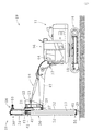
図1〜図5に示すように、本考案の一実施の形態に係る杭打ちアタッチメント10は、既存の油圧ショベル等の建設車両11のブーム12の先端に装着され、杭13の打ち込みに用いられるものである。建設車両11としては、クローラー等により走行する走行台車14と、走行台車14上に旋回可能に設けられた旋回台15と、旋回台15上にブーム12と共に設けられた運転席(キャビン)16を有するものが好適に用いられる。例えば建設車両11が油圧ショベルの場合、ブーム12の先端には、アーム(図示せず)を介してバケット(図示せず)が連結されており、ブーム12及びアームをそれぞれ走行台車11の前後方向に起伏(回動)させるブームシリンダー17(図1、図2)及びアームシリンダー18(図2)を備えている。そして、アーム及びバケットに代えて、ブーム12の先端に杭打ちアタッチメント10を装着することにより、建設車両11を杭打ち機19として使用することができる。
Next, embodiments of the present invention will be described with reference to the attached drawings for understanding of the present invention.
As shown in FIGS. 1 to 5, a
以下、杭打ちアタッチメント10の詳細について説明する。
まず、杭打ちアタッチメント10は、ブーム12の長手方向と直交する前後回転水平軸20(図2)と、前後回転水平軸20と直交する左右回転水平軸21(図1、図2)とを有し、前後回転水平軸20を介してブーム12の先側に回動可能に支持される装着部22を備えている。また、装着部22は、基側がブーム12の上部基側に連結されたアームシリンダー18の先側が連結されるアームシリンダー連結部23(図2)を有している。そして、杭打ちアタッチメント10は、左右回転水平軸21を介して装着部22に回動可能に保持された長尺の昇降ガイドセル24を備えている。さらに、装着部22は、昇降ガイドセル24を左右回転水平軸21を中心として左右方向に回転させる左右角度調整シリンダー25の基側が連結されるシリンダー基側連結部26(図1)を有し、昇降ガイドセル24は、左右角度調整シリンダー25の先側が連結されるシリンダー先側連結部27(図1、図2)を有している。
Hereinafter, the details of the
First, the
以上により、装着部22をブーム12の先側に容易に装着して、アームシリンダー18に連結すると共に、装着部22と昇降ガイドセル24を左右角度調整シリンダー25で連結することができる。そして、アームシリンダー18及び左右角度調整シリンダー25をそれぞれ伸縮させることにより、前後回転水平軸20を中心とする昇降ガイドセル24の前後方向回転(例えば±30度の可動範囲)及び左右回転水平軸21を中心とする昇降ガイドセル24の左右方向回転(例えば±15度の可動範囲)を行うことができる。このとき、装着部22には、図1、図2に示すように、前後回転水平軸20を中心とする昇降ガイドセル24の前後方向回転角度及び左右回転水平軸21を中心とする昇降ガイドセル24の左右方向回転角度を検出する角度センサー28が取付けられており、建設車両11が傾いている(杭13の設置面が傾斜面である)場合でも、昇降ガイドセル24と杭13の鉛直方向を確認することができる。
なお、建設車両11が油圧ショベルの場合、アームに対してバケットを回動可能に連結するバケットシリンダーを取外して、左右角度調整シリンダーとして利用することができるので、別途、シリンダーを用意する必要がない。
As described above, the mounting
When the
次に、杭打ちアタッチメント10は、昇降ガイドセル24の下端部に取付けられ、昇降ガイドセル24の長手方向を鉛直方向に一致させた状態で地中に打ち込まれて昇降ガイドセル24の下端側を固定する位置決めピン29を有している。これにより、杭13の打ち込み中に昇降ガイドセル24が傾いたり、捩れたりすることを防止して、杭13を正確に鉛直方向に打ち込むことができる。なお、位置決めピン29の長さ及び太さは適宜、選択することができる。
Next, the
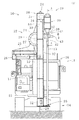
次に、杭打ちアタッチメント10は、昇降ガイドセル24の長手方向に沿って摺動可能に保持された杭打ち推力発生手段30を有している。杭打ち推力発生手段30の外側には、摺動部31が取付けられており、昇降ガイドセル24の側部(ここでは左側)には長手方向に沿ってガイド部32が設けられている。そして、摺動部31が、ガイド部32の幅方向両端部に係合する係合溝33(図1)を有することにより、杭打ち推力発生手段30は昇降ガイドセル24の長手方向に沿って摺動可能となっている。なお、杭打ち推力発生手段30としては、油圧ブレーカー(例えば5〜10tonクラス)が好適に用いられるが、これに限定されるものではなく、振動(推力)を発生させて杭13を打ち込むことができればよい。
Next, the
杭打ち推力発生手段30は、図3に示すように、シリンダー35と、シリンダー35内で昇降ガイドセル24の長手方向に沿って油圧で往復動するピストン36と、シリンダー35の先側に摺動可能に保持されピストン36で押圧されて摺動する摺動軸37とを有している。この杭打ち推力発生手段30には、図1〜図3に示すように、摺動軸37の先側に形成されたフランジ部38を介して、杭13の頭部を着脱可能に保持するチャック部41が連結されている。チャック部41は、図4に示すように、平面視して略コ字形に形成された受け金具42を有し、受け金具42に対し、チャック用シリンダー43で杭13を水平方向から押し付けるようにして固定することができる。本実施の形態では、左右角度調整シリンダー25及びチャック用シリンダー43はいずれも油圧シリンダーとし、建設車両11の油圧源を利用して、2つの油圧回路を適宜、電磁弁で切替えることにより、これらを動作させた。
As shown in FIG. 3, the pile driving force generating means 30 slides on the
また、摺動軸37の長手方向の途中には、小径部45が設けられ、摺動軸37の外周と小径部45の外周との間には、全周にわたって段差部46が形成されている。そして、シリンダー35内には、シリンダー35の長手方向と直交し、段差部46と係合するストッパーピン47が取付けられている。このストッパーピン47により、摺動軸37の摺動範囲(ストローク)が規制されるが、摺動軸37はチャック部41及び杭13と共に、シリンダー35の軸心を中心に回転可能である。図4に示したように、例えば溝形鋼を杭13として使用する際には、杭13の前後及び左右方向の向きを所定の向きに合わせる(水平面内での角度調整を行う)必要があるが、このように、摺動軸37が、チャック部41及び杭13と共に、シリンダー35の軸心を中心に回転可能となっていれば、杭13の頭部をチャック部41で保持した状態で容易に角度調整を行うことができる。
A
次に、杭打ちアタッチメント10は、昇降ガイドセル24に設けられ杭打ち推力発生手段30を昇降ガイドセル24の長手方向に沿って昇降させる昇降手段50を有している。この昇降手段50は、昇降ガイドセル24の上端側に回転可能に取付けられた駆動側スプロケット51(図1)と、昇降ガイドセル24の下端側に回転可能に取付けられた従動側スプロケット52(図1)と、駆動側スプロケット51に連結された駆動モーター53(図2)と、駆動側スプロケット51と従動側スプロケット52の間に巻回されて杭打ち推力発生手段30の外側(摺動部31)に連結されたチェーン54(図1)とを備えている。よって、駆動モーター53を正逆回転させることにより、杭打ち推力発生手段30を昇降ガイドセル24の長手方向に沿って昇降させることができる。そして、杭打ちを行う際に、昇降手段50で杭打ち推力発生手段30を下降させることにより発生する推力(例えば3〜5ton)を杭打ちの推力に付加して、杭打ち作業を効率的に行うことができる。また、杭13が打ち込まれる地盤が柔らかい場合や杭13の打ち始めは、杭打ち推力発生手段30を駆動せず、昇降手段50で杭打ち推力発生手段30を下降させるだけでも杭13を打ち込むことができる。なお、駆動モーター53には油圧モーターが好適に用いられる。
Next, the
次に、昇降ガイドセル24は、図1、図2、図5に示すように、昇降ガイドセル24の下側で杭13の外周を摺動可能に保持する下側ガイド55を備えている。この下側ガイドは、昇降ガイドセル24に固定されたベース部56を有しており、このベース部56には円弧状の切欠き57が形成されている。また、ベース部56上には、切欠き57の外側に沿うように円弧状のガイド部材58が設けられている。そして、ガイド部材58の内側でベース部56上に載置された回転部59は、杭13の外周に係合する切欠き状(コ字形)の係合部60を有しており、杭13と共に杭打ち推力発生手段30のシリンダー35の軸心を中心に回転可能となっている。これにより、先に説明したように、杭13を回転させて角度調整を行う際に、杭13の回転に追従させて回転部59を回転させることができるので、地中に打ち込まれる杭13を下側ガイド55で案内して、杭13の鉛直姿勢を維持することができ、傾き及び捩れの発生を防止することができる。また、下側ガイド55は、図5に示すように、一端側が回転部59上の回動支持部61によって垂直面内で回動可能に支持され、係合部60の開口側を開閉して杭13の端面に当接する当接片62を有することが好ましい。当接片62を上方に回動して係合部60を開けば、杭13を係合部60に簡単に係合させることができ、当接片62を下方に回動して係合部60を閉じれば、杭13の端面に当接片62を当接させて係合部60に杭13を保持することができ、杭13の傾き及び捩れの発生防止効果を高めることができる。
Next, as shown in FIGS. 1, 2 and 5, the elevating
次に、建設車両11の運転席16には、図2に示すように、角度センサー28(図1)で検出された昇降ガイドセル24の前後方向回転角度及び左右方向回転角度を表示する角度表示計64が取付けられている。運転者は角度表示計64を確認しながら建設車両11(ブームシリンダー17、アームシリンダー18、及び左右角度調整シリンダー25)を操作することにより、昇降ガイドセル24の前後方向及び左右方向の回転角度を容易に調整して、杭13を確実に鉛直に打ち込むことができる。このとき、昇降ガイドセル24は、図1に示すように、運転席16の正面側に位置し、チャック部41に保持された杭13及び杭13の打ち込み位置を運転席16から視認できるので、他の作業者の指示に頼る必要もなく、操作性及び省力性を向上させることができる。
Next, on the driver's
以上、本考案の実施の形態を説明したが、本考案は、上記した形態に限定されるものでなく、要旨を逸脱しない条件の変更等は全て本考案の適用範囲である。
例えば、チャック部の構造は使用する杭の形状等に応じて、適宜、選択することができる。また、下側ガイドも昇降ガイドセルの下側で杭を案内することができればよく、その構造は、上記実施の形態に限定されることなく、適宜、選択することができる。上記実施の形態では、杭打ち推力発生手段の摺動軸がチャック部及び杭と共に、シリンダーの軸心を中心に回転可能な構造としたが、丸パイプを杭として使用する場合は、水平面内での角度調整を行う必要がないので、摺動軸は回転できなくてもよい。
As mentioned above, although embodiment of this invention was described, this invention is not limited to the above-mentioned form, The change of the conditions which do not deviate from a summary, etc. are all the application scope of this invention.
For example, the structure of the chuck portion can be appropriately selected according to the shape of the pile used. Moreover, the lower guide may also be able to guide the pile on the lower side of the elevation guide cell, and the structure thereof can be selected as appropriate without being limited to the above embodiment. In the above embodiment, the sliding shaft of the pile driving thrust generating means is configured to be rotatable about the axis of the cylinder together with the chuck portion and the pile, but when using a round pipe as a pile, it may be in a horizontal plane The sliding shaft may not be able to rotate because it is not necessary to adjust the angle of.
10:杭打ちアタッチメント、11:建設車両、12:ブーム、13:杭、14:走行台車、15:旋回台、16:運転席(キャビン)、17:ブームシリンダー、18:アームシリンダー、19:杭打ち機、20:前後回転水平軸、21:左右回転水平軸、22:装着部、23:アームシリンダー連結部、24:昇降ガイドセル、25:左右角度調整シリンダー、26:シリンダー基側連結部、27:シリンダー先側連結部、28:角度センサー、29:位置決めピン、30:杭打ち推力発生手段、31:摺動部、32:ガイド部、33:係合溝、35:シリンダー、36:ピストン、37:摺動軸、38:フランジ部、41:チャック部、42:受け金具、43:チャック用シリンダー、45:小径部、46:段差部、47:ストッパーピン、50:昇降手段、51:駆動側スプロケット、52:従動側スプロケット、53:駆動モーター、54:チェーン、55:下側ガイド、56:ベース部、57:切欠き、58:ガイド部材、59:回転部、60:係合部、61:回動支持部、62:当接片、64:角度表示計 10: pile driving attachment, 11: construction vehicle, 12: boom, 13: pile, 14: traveling carriage, 15: swivel, 16: driver's seat (cabin), 17: boom cylinder, 18: arm cylinder, 19: pile Driving machine, 20: front and rear rotation horizontal axis, 21: left and right rotation horizontal axis, 22: mounting portion, 23: arm cylinder connecting portion, 24: elevation guide cell, 25: left and right angle adjusting cylinder, 26: cylinder base side connecting portion, 27: cylinder front side connecting portion, 28: angle sensor, 29: positioning pin, 30: pile driving force generating means, 31: sliding portion, 32: guide portion, 33: engagement groove, 35: cylinder, 36: piston , 37: sliding shaft, 38: flange portion, 41: chuck portion, 42: receiving bracket, 43: cylinder for chuck, 45: small diameter portion, 46: step portion, 47: stopper , 50: lifting means, 51: drive side sprocket, 52: driven sprocket, 53: drive motor, 54: chain, 55: lower guide, 56: base portion, 57: notch, 58: guide member, 59 : Rotating part, 60: Engaging part, 61: Rotating support part, 62: Contact piece, 64: Angle indicator
Claims (9)
前記ブームの長手方向と直交する前後回転水平軸と、該前後回転水平軸と直交する左右回転水平軸とを有し、前記前後回転水平軸を介して前記ブームの先側に回動可能に支持される装着部と、前記左右回転水平軸を介して前記装着部に回動可能に保持された長尺の昇降ガイドセルと、前記装着部に取付けられ前記前後回転水平軸を中心とする前記昇降ガイドセルの前後方向回転角度及び前記左右回転水平軸を中心とする前記昇降ガイドセルの左右方向回転角度を検出する角度センサーと、前記昇降ガイドセルの下端部に取付けられ、該昇降ガイドセルの長手方向を鉛直方向に一致させた状態で地中に打ち込まれて該昇降ガイドセルの下端側を固定する位置決めピンと、前記昇降ガイドセルの長手方向に沿って摺動可能に保持された杭打ち推力発生手段と、前記昇降ガイドセルに設けられ該杭打ち推力発生手段を前記昇降ガイドセルの長手方向に沿って昇降させる昇降手段と、前記杭打ち推力発生手段に連結され前記杭の頭部を着脱可能に保持するチャック部と、地中に打ち込まれる前記杭を前記昇降ガイドセルの下側で案内する下側ガイドとを備えたことを特徴とする杭打ちアタッチメント。 In the piling attachment attached to the tip side of the boom of the construction vehicle and used for driving a pile,
It has a front and rear rotation horizontal axis orthogonal to the longitudinal direction of the boom, and a left and right rotation horizontal axis orthogonal to the front and rear rotation horizontal axis, and is rotatably supported on the tip side of the boom via the front and rear rotation horizontal axis. Mounting portion, a long elevating guide cell rotatably held by the mounting portion via the horizontal rotational horizontal axis, and the vertical movement around the longitudinal horizontal rotational axis attached to the mounting portion An angle sensor for detecting the longitudinal rotation angle of the guide cell and the lateral rotation angle of the elevation guide cell around the horizontal rotational horizontal axis, and attached to the lower end of the elevation guide cell, the longitudinal length of the elevation guide cell A positioning pin which is driven into the ground with its direction aligned in the vertical direction to fix the lower end side of the elevating guide cell, and a pile driving force slidably held along the longitudinal direction of the elevating guide cell Raw means, raising and lowering means provided on the raising and lowering guide cell to raise and lower the pile driving force generating means along the longitudinal direction of the raising and lowering guide cell, and the pile driving force generating means A pile driving attachment characterized by comprising a chuck portion capable of being held, and a lower guide for guiding the pile driven into the ground below the elevator guide cell.
Priority Applications (1)
| Application Number | Priority Date | Filing Date | Title |
|---|---|---|---|
| JP2019000461U JP3221669U (en) | 2019-02-12 | 2019-02-12 | Pile driving attachment and pile driver |
Applications Claiming Priority (1)
| Application Number | Priority Date | Filing Date | Title |
|---|---|---|---|
| JP2019000461U JP3221669U (en) | 2019-02-12 | 2019-02-12 | Pile driving attachment and pile driver |
Publications (1)
| Publication Number | Publication Date |
|---|---|
| JP3221669U true JP3221669U (en) | 2019-06-13 |
Family
ID=66810896
Family Applications (1)
| Application Number | Title | Priority Date | Filing Date |
|---|---|---|---|
| JP2019000461U Active JP3221669U (en) | 2019-02-12 | 2019-02-12 | Pile driving attachment and pile driver |
Country Status (1)
| Country | Link |
|---|---|
| JP (1) | JP3221669U (en) |
Cited By (2)
| Publication number | Priority date | Publication date | Assignee | Title |
|---|---|---|---|---|
| JP2021139155A (en) * | 2020-03-05 | 2021-09-16 | 大都技研株式会社 | Position determination device |
| CN114645541A (en) * | 2022-04-07 | 2022-06-21 | 徐州徐工挖掘机械有限公司 | Pile driver control method and pile driver |
-
2019
- 2019-02-12 JP JP2019000461U patent/JP3221669U/en active Active
Cited By (3)
| Publication number | Priority date | Publication date | Assignee | Title |
|---|---|---|---|---|
| JP2021139155A (en) * | 2020-03-05 | 2021-09-16 | 大都技研株式会社 | Position determination device |
| JP7195009B2 (en) | 2020-03-05 | 2022-12-23 | 大都技研株式会社 | positioning device |
| CN114645541A (en) * | 2022-04-07 | 2022-06-21 | 徐州徐工挖掘机械有限公司 | Pile driver control method and pile driver |
Similar Documents
| Publication | Publication Date | Title |
|---|---|---|
| US9777459B2 (en) | Attachment for a skid steer loader and method of use thereof | |
| US20070127990A1 (en) | Lead alignment attachment | |
| JP3221669U (en) | Pile driving attachment and pile driver | |
| US20220154569A1 (en) | Drill control device | |
| EP2084332B1 (en) | System for mounting a pile driver | |
| JP4545818B2 (en) | Excavation support apparatus and excavation support method | |
| JP6308990B2 (en) | Attachment for removing underground obstacles and method for removing underground obstacles | |
| JP2020143440A (en) | Pile press-in machine and pile press-in construction method | |
| JP6627905B2 (en) | Slope drilling method | |
| JP2021098963A (en) | Steel pipe pile burying device | |
| JP3167247B2 (en) | Hydraulic excavator equipped with ground hardness measurement device | |
| JP2922102B2 (en) | Slope drilling equipment | |
| JP3936349B2 (en) | Excavator | |
| JP6247457B2 (en) | Construction machinery | |
| JP5921256B2 (en) | Pile driver | |
| JP3366602B2 (en) | Front attachment support device for ground excavator | |
| KR101526806B1 (en) | Construction device for foundation work | |
| JPS6227542Y2 (en) | ||
| RU60587U1 (en) | DRILLING COMPLEX | |
| JP2002147162A (en) | Caisson type pile excavator | |
| KR20210061763A (en) | pile straightness correction unit and pile driving hammer using thereof | |
| JPH0634425Y2 (en) | Posture correction device | |
| US20210002849A1 (en) | Drill Adaptor | |
| JP2001140575A (en) | Anchor executing machine | |
| KR20200092092A (en) | Earth drilling machine for constructability improvement |
Legal Events
| Date | Code | Title | Description |
|---|---|---|---|
| A521 | Request for written amendment filed |
Free format text: JAPANESE INTERMEDIATE CODE: A523 Effective date: 20190402 |
|
| R150 | Certificate of patent or registration of utility model |
Ref document number: 3221669 Country of ref document: JP Free format text: JAPANESE INTERMEDIATE CODE: R150 |
|
| R250 | Receipt of annual fees |
Free format text: JAPANESE INTERMEDIATE CODE: R250 |
|
| R250 | Receipt of annual fees |
Free format text: JAPANESE INTERMEDIATE CODE: R250 |
|
| R250 | Receipt of annual fees |
Free format text: JAPANESE INTERMEDIATE CODE: R250 |