JP3217618U - Frequent urine eliminating pusher - Google Patents
Frequent urine eliminating pusher Download PDFInfo
- Publication number
- JP3217618U JP3217618U JP2018001119U JP2018001119U JP3217618U JP 3217618 U JP3217618 U JP 3217618U JP 2018001119 U JP2018001119 U JP 2018001119U JP 2018001119 U JP2018001119 U JP 2018001119U JP 3217618 U JP3217618 U JP 3217618U
- Authority
- JP
- Japan
- Prior art keywords
- pressing
- pusher
- spherical
- arm
- heel
- Prior art date
- Legal status (The legal status is an assumption and is not a legal conclusion. Google has not performed a legal analysis and makes no representation as to the accuracy of the status listed.)
- Expired - Fee Related
Links
Images
Landscapes
- Finger-Pressure Massage (AREA)
Abstract
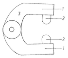
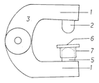
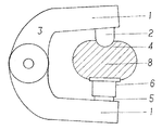
【課題】押圧アームの両先端部に球面突起部材を装着し、突起部位をもって垂直に三陰交の壺を押圧することで頻尿を解消する壺押し器を提供する。【解決手段】押圧アーム1の先端部の双方に球面突起部材2を装着して壺押し器本体3を形成したもので、押圧アームを開き突起部分で三陰交の壺部位4をとらえ、垂直に押圧できる機能を整え、併せて、壺押し器本体の球面突起部材の一方の基軸5に筒を設けて嵌脱自在の平面盤固形部材6を回動可能な状態で嵌装し、壺裏側の押圧力を分散させ皮膚面への刺激の緩和を図り、相乗効果により三陰交の壺への押圧を一段と向上させ良好な刺激を生むようにした。【選択図】図3Provided is a pusher that eliminates frequent urination by attaching spherical protruding members to both end portions of a pressing arm and pressing a three-sided fold vertically with the protruding portion. A spherical pusher body 2 is mounted on both ends of a pressing arm 1 to form a pusher body 3. The pressing arm is opened, and a three-part crossing heel part 4 is captured by the protruding portion and pressed vertically. At the same time, a cylinder is provided on one base shaft 5 of the spherical protrusion member of the presser body, and a detachable plane board solid member 6 is fitted in a rotatable state, so The pressure was dispersed to alleviate the irritation to the skin surface, and the pressure on the folds of the three-yongko was further improved by a synergistic effect to produce good irritation. [Selection] Figure 3
Description
本考案はふとんはさみの挟持力アームをヒントに形状、機能、構造を押圧力に換えることで価値を生むよう発想の転換を図り、人体の特定部位を垂直に押すことで効き目のある構造に形成し、三陰交の壺を押圧することで、頻尿を解消するとした壺押し器に関するものである。 The present invention uses a futon scissor pinching force arm as a hint to change the shape, function, and structure to a pressing force to change the way of thinking, and by pushing a specific part of the human body vertically, it forms an effective structure In addition, the present invention relates to a pressing device that is intended to eliminate frequent urination by pressing a three-sided fold.
従来の壺押し器の壺に対する押圧は、使用する者が支持アームを両手で持ち、挟むなどして壺を押圧するとした機能であって、本考案で指示している壺押し器のような形状はなく、押圧力を内蔵した壺押し器であっても取り扱いが複雑で操作に手間が掛かるなどの問題点があった。 The pressing of the conventional pusher against the heel is a function that the user holds the support arm with both hands and presses the heel by pinching, etc., and is shaped like the pusher indicated in the present invention. However, even a pressing device with a built-in pressing force has problems such as complicated handling and troublesome operation.
これまでの壺押し器の機能においては、その作用により壺への押圧面をとらえる部材の先端部分が多面的であり、特定の壺を専門的にとらえ諸症状の解消を図る押圧部材としては効能に難点があったのでそれを解決するとして、本考案による球面突起の作用で壺への押圧を垂直に当てる特別機能をもって、三陰交の壺を押圧し頻尿を解消するに適した構造に組み換え、欠点を解決しようとするものである。 In the function of the conventional pusher, the tip part of the member that catches the pressing surface to the heel by its action is multifaceted, and it is effective as a pressing member that specially catches a specific heel and aims to eliminate various symptoms In order to solve this problem, recombination into a structure suitable for resolving frequent urination by pressing the three-sided fold with the special function of vertically applying the pressure on the heel by the action of the spherical projection according to the present invention, It tries to solve the drawbacks.
本考案はふとんはさみの形状、機能、構造などを新たな発想に転換して価値を生むとしたもので、アームの機能に保有する挟持力を壺を押圧する力に換え特定の壺を押すことで、頻尿を解決する壺押し器として考案したものである。本構造は一対の押圧力のあるアームの双方の先端部に球面突起部材を装着することにより、壺への押圧角度が皮膚面に垂直に当たることで、三陰交の壺を適確に押す作用を果たし、刺激を与え頻尿を解消することに適した壺押し器としたものである。更に本機能の向上を図るため押圧アームの先端部に装着の球面突起部材の一方に嵌脱自在の平面盤固形部材を回動可能に嵌装することで、壺裏側の皮膚面に受ける押圧力を分散し刺激を緩和する作用を果たしながら、壺への押圧力は一段と向上させるとした相乗効果と相俟って問題点を解決するに至った壺押し器である。 The present invention aims to create value by changing the shape, function, and structure of futon scissors to a new concept. Therefore, it was devised as a pusher to solve frequent urination. In this structure, spherical protrusions are attached to the tip of both arms with a pair of pressing forces, so that the pressing angle against the heel hits the skin surface perpendicularly, thereby pressing the three-sided fold accurately. It is a pusher suitable for stimulating and eliminating frequent urination. In order to further improve this function, a pressing force applied to the skin surface on the back side of the heel by rotatably fitting a flat plate solid member that can be fitted and removed to one of the spherical protruding members mounted on the tip of the pressing arm. This is a pusher that has solved the problem in combination with the synergistic effect of further improving the pressing force on the heel while dispersing and stimulating the stimuli.
上記のように本考案の壺押し器により、その他の壺への押圧活用は勿論、特定する三陰交の壺への押圧する刺激効果で頻尿を解消する壺押し器として役立つものである。 As described above, the pusher of the present invention is useful as a pusher that eliminates frequent urine due to the stimulating effect of pressing on a specific three-yen fold as well as the use of pressing on other folds.
以下本考案を実施するための形態について説明する。押圧アームの先端部双方に球面突起部材を設け、この突起部分の機能によって三陰交の壺に垂直に押圧することで刺激を与えて頻尿を解消するとしたものである。
更に、押圧力の効果を向上するための球面突起部材の一方に嵌脱自在の平面盤固形部材を回動可能な状態で嵌装することによって、球面突起部材の当たる壺の接点と、平面盤固形部材で受ける皮膚面の刺激を緩和することにより、本機能の相乗効果を生かすことで、押す力の強化の向上を図り、壺への効能を一段と高めるものとした壺押し器の構造である。これを使用するときは双方の押圧アームを開き、球面突起部分で三陰交の壺を押圧することで頻尿を解消することは勿論、その他の壺を押圧することにも対応可能であることから適応する他の壺を押すことで諸症状への押圧効果にも役立つものとした。Hereinafter, embodiments for carrying out the present invention will be described. Spherical protrusions are provided on both ends of the pressing arm, and the function of the protrusions is used to press the urine of the three-yen cross perpendicularly to provide stimulation and eliminate frequent urine.
Further, a flat plate solid member that can be freely fitted and removed is fitted in one of the spherical projection members for improving the effect of the pressing force in a rotatable state, so that the contact point of the flange that the spherical projection member hits and the plane plate It is a structure of a pusher that further enhances the effect on the heel by improving the pushing force by taking advantage of the synergistic effect of this function by relaxing the stimulation of the skin surface received by the solid member . When using this, both pressing arms are opened, and it is possible to eliminate frequent urination by pressing the three-sided folds with the spherical protrusions, and it is also adaptable to pressing other folds It was also helpful to press the other wrinkles to press the various symptoms.
以下、添付図面に従って実施例を説明する。図3は本考案の一実施例を示す正面図であって、押圧アーム1の先端部の双方に球面突起部材2を装着して、壺押し器本体3を形成するもので、押圧アーム1を開き其々の突起部分の一方は三陰交の壺部位4をとらえ垂直に押圧し、他方は壺の裏側を垂直に押圧することで頻尿を解消するとした主な機能をもって、簡潔な構造に纏め簡素な形状にしたことで取り扱いが容易で収納も簡単であることから使用頻度も難なく、手軽に実施できるようにしたものである。 Embodiments will be described below with reference to the accompanying drawings. FIG. 3 is a front view showing an embodiment of the present invention, in which a
上記の壺押し器本体3の機能を向上させるため、球面突起部材2の一方の基軸5に嵌脱自在の平面盤固形部材6を回動可能な状態で取り付けて使用するため、この部材6の平面盤の下部中心に筒7を設け嵌装するとしたことで、壺裏側の押圧力を分散させ皮膚面への刺激の緩和を図りながら、特定の壺への押圧力を一段と増強させる相乗効果を形成することをもって、三陰交の壺部位4を両足首の近く内側にある三陰交の壺断面図8で示すとおりの壺押圧が実施できたところである。 In order to improve the function of the
1 押圧アーム
2 球面突起部材
3 壺押し器本体
4 三陰交の壺部位
5 球面突起部材基軸
6 平面盤固形部材
7 平面盤固形部材の筒
8 両足首近く内側にある三陰交の壺断面図DESCRIPTION OF
Claims (2)
Priority Applications (1)
| Application Number | Priority Date | Filing Date | Title |
|---|---|---|---|
| JP2018001119U JP3217618U (en) | 2018-03-07 | 2018-03-07 | Frequent urine eliminating pusher |
Applications Claiming Priority (1)
| Application Number | Priority Date | Filing Date | Title |
|---|---|---|---|
| JP2018001119U JP3217618U (en) | 2018-03-07 | 2018-03-07 | Frequent urine eliminating pusher |
Publications (1)
| Publication Number | Publication Date |
|---|---|
| JP3217618U true JP3217618U (en) | 2018-08-23 |
Family
ID=63245153
Family Applications (1)
| Application Number | Title | Priority Date | Filing Date |
|---|---|---|---|
| JP2018001119U Expired - Fee Related JP3217618U (en) | 2018-03-07 | 2018-03-07 | Frequent urine eliminating pusher |
Country Status (1)
| Country | Link |
|---|---|
| JP (1) | JP3217618U (en) |
-
2018
- 2018-03-07 JP JP2018001119U patent/JP3217618U/en not_active Expired - Fee Related
Similar Documents
| Publication | Publication Date | Title |
|---|---|---|
| KR101627174B1 (en) | Beauty instrument | |
| JP3166299U (en) | Massage equipment | |
| CN103417357A (en) | Neck massager | |
| US3850163A (en) | Stride and knead massager | |
| JP2012217516A (en) | Roller for massage and roller type massage instrument using the same | |
| US20040015110A1 (en) | Massaging device | |
| JP3217618U (en) | Frequent urine eliminating pusher | |
| JP3141605U (en) | Nose muscle correction roller | |
| CN209790349U (en) | Hand-held spine clamping push wheel | |
| KR19980082899A (en) | Kobo shaper with snoring function | |
| KR101639526B1 (en) | Chair adhered acupressure bar | |
| KR200418215Y1 (en) | Acupuncture needles | |
| CN206026639U (en) | Improved hand-held massager | |
| JP3197518U (en) | Massage equipment | |
| KR200305340Y1 (en) | Acupressure Device for Fingers | |
| KR200447358Y1 (en) | Hand chiropractor | |
| CN209450921U (en) | A bladder meridian massage clip | |
| CN206482805U (en) | A kind of shank massage device and massage armchair of hiding roller | |
| CN206151815U (en) | Human massage stick | |
| CN219941209U (en) | Hand-held acupoint massager | |
| TWM491375U (en) | Eyelash curler structure improvement | |
| CN104473756B (en) | A kind of magnetic therapy eye massage device | |
| JP5927657B1 (en) | Shiatsu | |
| CN209884753U (en) | Moxibustion massage sole | |
| JP7038286B1 (en) | Presser |
Legal Events
| Date | Code | Title | Description |
|---|---|---|---|
| A521 | Request for written amendment filed |
Free format text: JAPANESE INTERMEDIATE CODE: A523 Effective date: 20180601 |
|
| R150 | Certificate of patent or registration of utility model |
Ref document number: 3217618 Country of ref document: JP Free format text: JAPANESE INTERMEDIATE CODE: R150 |
|
| LAPS | Cancellation because of no payment of annual fees |