JP3217436U - Game controller control unit - Google Patents
Game controller control unit Download PDFInfo
- Publication number
- JP3217436U JP3217436U JP2018001945U JP2018001945U JP3217436U JP 3217436 U JP3217436 U JP 3217436U JP 2018001945 U JP2018001945 U JP 2018001945U JP 2018001945 U JP2018001945 U JP 2018001945U JP 3217436 U JP3217436 U JP 3217436U
- Authority
- JP
- Japan
- Prior art keywords
- game controller
- control unit
- user
- force
- support arm
- Prior art date
- Legal status (The legal status is an assumption and is not a legal conclusion. Google has not performed a legal analysis and makes no representation as to the accuracy of the status listed.)
- Active
Links
- 239000000463 material Substances 0.000 claims description 4
- 210000003811 finger Anatomy 0.000 description 8
- 210000004247 hand Anatomy 0.000 description 3
- 238000000034 method Methods 0.000 description 3
- 238000011084 recovery Methods 0.000 description 3
- 125000002066 L-histidyl group Chemical group [H]N1C([H])=NC(C([H])([H])[C@](C(=O)[*])([H])N([H])[H])=C1[H] 0.000 description 2
- 210000003813 thumb Anatomy 0.000 description 2
- 238000011161 development Methods 0.000 description 1
- 238000009510 drug design Methods 0.000 description 1
- 235000013372 meat Nutrition 0.000 description 1
- 239000002184 metal Substances 0.000 description 1
- 238000012827 research and development Methods 0.000 description 1
Images


Landscapes
- Switches With Compound Operations (AREA)
Abstract
【課題】使用者が自分で装設可能なゲームコントローラーの制御ユニットを提供する。【解決手段】ゲームコントローラーの制御ユニットであって、高さが異なる第一端311及び第二端312を有する少なくとも1つの操作部材31と、第一端及び第二端に連結される支持アームと、第一端の上表面に設置され、使用者による力が加えられる位置として配置される接触部と、第一端の下表面に設置され、ゲームコントローラー内のスイッチを作動させるように配置される作動部と、操作部材の第二端に設置され、且つ選択的に使用される工具によりゲームコントローラーに固定される少なくとも1つの固定部とを備え、使用者による力が接触部に加えられると、支持アームが初期位置からシフトすると共にゲームコントローラー内のスイッチを作動させるように作動部と連動し、使用者による力が接触部に加えられないと、支持アームが初期位置に復位される。【選択図】図5A game controller control unit that can be installed by a user is provided. A control unit of a game controller, comprising at least one operation member 31 having a first end 311 and a second end 312 having different heights, and a support arm connected to the first end and the second end. Installed on the upper surface of the first end and arranged as a position where a force is applied by the user, and installed on the lower surface of the first end and arranged to operate a switch in the game controller. An actuating portion and at least one fixing portion that is installed at the second end of the operation member and is fixed to the game controller by a tool that is selectively used, and when a force by the user is applied to the contact portion, The support arm shifts from the initial position and works with the actuating part to actuate a switch in the game controller. Arm is repositioned to the initial position. [Selection] Figure 5
Description
本考案は、ゲームコントローラーの制御ユニットに関し、特に、使用者が自分でゲームコントローラーに装設可能である制御ユニットに関する。 The present invention relates to a control unit for a game controller, and more particularly, to a control unit that can be installed on a game controller by a user.
ビデオゲーム産業全体の発展を考えると、ゲームコントローラーは全てのゲームマシンにおいて欠くことのできないものであり、ゲームプレイヤーはこれを使用してビデオゲーム内のキャラクターやアイテムを操作することによりゲームのクリアを目指す。このため、ゲームプレイヤーの操作テク以外にも、ゲームプレイヤーが操作しやすいゲームコントローラーを如何に設計するかについても業界では研究開発に尽力している。 Considering the development of the entire video game industry, game controllers are indispensable for all game machines, and game players can use them to manipulate characters and items in video games to clear the game. aim. For this reason, in addition to game player operation techniques, the industry is also devoted to research and development on how to design game controllers that are easy for game players to operate.
現在、ほとんどのゲームコントローラーは両手で握って操作するように設計されており、これらの周知のゲームコントローラーには通常機能が異なる複数の制御部材が設置されることにより、使用者に多様な操作方式を提供している。例えば、ゲームコントローラーの上部に設置されるボタン、十字キー、及びジョイスティック等がある。通常上部に装設されるこれらの制御部材は使用者の親指で操作される。ゲームコントローラーの前部に設置される側面ボタン及びボタンは使用者の人差し指で操作され、ゲームコントローラーの底部に設置されるトリガーは使用者の中指または薬指で操作される。 Currently, most game controllers are designed to be operated with both hands, and these well-known game controllers are equipped with multiple control members with different normal functions, so that various operation methods can be used by the user. Is provided. For example, there are a button, a cross key, a joystick, and the like installed at the top of the game controller. Normally, these control members mounted on the upper part are operated with the thumb of the user. The side buttons and buttons installed at the front of the game controller are operated with the user's index finger, and the trigger installed at the bottom of the game controller is operated with the user's middle finger or ring finger.
特に、eスポーツの隆盛に伴い、ゲーム産業全体が急激に発展している。ゲームコントローラーの操作方法も多様化し、基本的な操作機能以外、ゲームコントローラーの操作感及びスムーズさも使用者にとっては購入の目安となった。但し、各使用者の操作習慣には違いがあるため、個人に合わせてカスタマイズ可能にするためには、使用者が自分で装設可能なゲームコントローラーを設計する必要があった。 In particular, along with the rise of e-sports, the entire game industry is rapidly developing. The operation method of the game controller is diversified, and in addition to the basic operation functions, the operational feeling and smoothness of the game controller have become an indication of purchase for the user. However, since there are differences in the operation habits of each user, it was necessary to design a game controller that the user can install himself / herself in order to be customizable according to the individual.
そこで、本考案者は上記の欠点が改善可能と考え、鋭意検討を重ねた結果、合理的設計で上記の課題を効果的に改善する本考案の提案に到った。 Therefore, the present inventor considered that the above-described drawbacks can be improved, and as a result of intensive studies, the present inventor has arrived at a proposal of the present invention that effectively improves the above-described problems with a rational design.
本考案はこうした状況に鑑みてなされたものであり、その目的は、ゲームコントローラーの制御ユニットを提供することにある。すなわち、使用者がゲームをスムーズに操作可能にするためにゲームコントローラーの底部に制御ユニットが設置される。制御ユニットはゲームコントローラー本体に着脱可能である。 The present invention has been made in view of such circumstances, and an object thereof is to provide a control unit of a game controller. That is, a control unit is installed at the bottom of the game controller so that the user can operate the game smoothly. The control unit is detachable from the game controller body.
上述した課題を解決し、目的を達成するために、本考案はゲームコントローラーの制御ユニットであって、高さが異なる第一端及び第二端を有する少なくとも1つの操作部材と、前記第一端及び前記第二端に連結される支持アームと、前記第一端の上表面に設置され、使用者による力が加えられる位置として配置される接触部と、前記第一端の下表面に設置され、前記ゲームコントローラー内のスイッチを作動させるように配置される作動部と、前記操作部材の前記第二端に設置され、且つ選択的に使用される工具により前記ゲームコントローラーに固定される少なくとも1つの固定部とを備え、使用者による力が前記接触部に加えられると、前記支持アームが初期位置からシフトすると共に前記ゲームコントローラー内の前記スイッチを作動させるように前記作動部と連動し、使用者による力が前記接触部に加えられないと、前記支持アームが前記初期位置に復位されることを特徴とするゲームコントローラーの制御ユニット。 In order to solve the above-described problems and achieve the object, the present invention is a control unit of a game controller, and includes at least one operation member having a first end and a second end having different heights, and the first end. And a support arm connected to the second end, a contact portion installed on the upper surface of the first end and arranged as a position where a force is applied by a user, and installed on the lower surface of the first end. An actuating portion arranged to actuate a switch in the game controller, and at least one fixed to the game controller by a tool that is installed at the second end of the operation member and is selectively used And when the force applied by the user is applied to the contact portion, the support arm shifts from the initial position and creates the switch in the game controller. In conjunction with the actuating portion so as to, when the force by the user is not applied to the contact portion, the control unit of the game controller, wherein the supporting arm is repositioned to the initial position.
また、本考案はゲームコントローラーの制御ユニットであって、高さが異なる第一端及び第二端を有し、弾性を有すると共にフレキシブルな材質で形成される複数の操作部材と、前記第一端及び前記第二端に連結される支持アームと、前記第一端の上表面に設置され、使用者による力が加えられる位置として配置される接触部と、前記第一端の下表面に設置され、前記ゲームコントローラー内のスイッチを作動させるように配置される作動部と、前記操作部材の前記第二端が延伸されて交差する箇所に設置され、且つ選択的に使用される工具により前記ゲームコントローラーに固定される固定部とを備え、使用者による力が前記接触部に加えられると、前記支持アームが初期位置からシフトすると共に前記ゲームコントローラー内の前記スイッチを作動させるように前記作動部と連動し、使用者による力が前記接触部に加えられないと、前記支持アームが前記初期位置に復位されることを特徴とするゲームコントローラーの制御ユニット。 The present invention is a control unit for a game controller having a first end and a second end having different heights, a plurality of operation members formed of a flexible material having elasticity and the first end. And a support arm connected to the second end, a contact portion installed on the upper surface of the first end and arranged as a position where a force is applied by a user, and installed on the lower surface of the first end. The game controller by means of a tool that is installed at an intersection where the second end of the operation member extends and intersects and is selectively used to operate a switch in the game controller And when the force applied by the user is applied to the contact portion, the support arm shifts from an initial position and the switch in the game controller. In conjunction with the actuating portion to actuate the switch, a force by the user is not applied to the contact portion, the control unit of the game controller, wherein the supporting arm is repositioned to the initial position.
本考案に係るゲームコントローラーの制御ユニットは、複数の操作部材の支持アームが両端に高さが異なる接触部及び固定部に連結され、使用者が接触部に力を加えると、他の面の作動部が連動されてゲームコントローラー内の制御スイッチを作動させる。また、使用者が操作を終了すると、支持アームが初期位置に復位される。なお、ねじ及びねじ穴の設計により、ゲームコントローラーに堅固に螺合され、使用者が自分の好みの操作感に合わせて自分で制御ユニットを装設可能になる。 In the control unit of the game controller according to the present invention, the support arms of the plurality of operation members are connected to the contact portions and the fixed portions having different heights at both ends, and when the user applies a force to the contact portions, the operation of the other surface is performed. The parts are linked to operate the control switch in the game controller. When the user finishes the operation, the support arm is restored to the initial position. The design of the screw and the screw hole allows the user to install the control unit by himself / herself in accordance with his / her favorite operation feeling by being firmly screwed into the game controller.
本考案のゲームコントローラーの制御ユニットによれば、ゲームコントローラーに効果的に固定される。また、使用者が自分で着脱可能になり、ゲームコントローラーの操作時のスムーズさ及び感触を使用者が満足するものにできる。 According to the control unit of the game controller of the present invention, it is effectively fixed to the game controller. Also, the user can attach and detach himself / herself, and the user can satisfy the smoothness and feel when operating the game controller.
以下に図面を参照して、本考案を実施するための形態について、詳細に説明する。なお、本考案は、以下に説明する実施形態に限定されるものではない。 Hereinafter, embodiments for carrying out the present invention will be described in detail with reference to the drawings. The present invention is not limited to the embodiments described below.
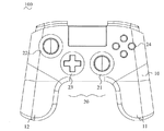
以下、本考案のゲームコントローラー100を図1〜図4に基づいて説明する。ゲームコントローラー100はハウジング10と、複数の制御モジュール20と、制御ユニット30と、固定部材40とを備える。
Hereinafter, the
ハウジング10には、使用者がゲームコントローラー100を操作する際に使用される左ハンドル11及び右ハンドル12が設置される。使用者が操作する場合、手で左ハンドル11及び右ハンドル12を握る。
The
複数の制御モジュール20は右アナログスティック21と、左アナログスティック22と、十字キー23と、ボタン24と、前ボタン25と、側面ボタン26とを備える。右アナログスティック21、左アナログスティック22、十字キー23、及びボタン24はゲームコントローラー100の上部に設置され、通常、使用者が左右の手の親指で操作を行う。また、前ボタン25はゲームコントローラー100の前部の左右両側の上方に設置され、前ボタン25に対応する位置の下方にも左右両側の側面ボタン26が設置され、通常、使用者が左右の手の人差し指または中指で操作を行う。制御ユニット30はゲームコントローラー100の底部に設置され、通常、使用者が左右の手の中指または薬指で操作を行う。
The plurality of
図5及び図6は本考案の実施形態に係る制御ユニット30の構造を示す図である。本実施形態では、前記制御ユニット30の外形は90度ひっくり返したX字型を呈し、その中心点はゲームコントローラー100に装設される位置であり、X字型の四端は使用者による力が加えられる位置である。
5 and 6 are views showing the structure of the
図4、図5、及び図6を参照し、制御ユニット30のゲームコントローラー100側と反対する面は制御ユニット30の上表面と定義され、すなわち、使用者による力が加えられる面である。制御ユニット30のゲームコントローラー100側の面は制御ユニット30の下表面と定義される。
4, 5, and 6, a surface opposite to the
本実施形態では、制御ユニット30のX字型の内の一端は操作部材31と定義され、各操作部材31は高さが異なる第一端311及び第二端312を有する。第一端311は第二端312より高く、両端の間は支持アーム32により連結される。第一端311の上表面には接触部33が設けられ、前記接触部33は使用者による押圧力が加えられる位置である。よって、前記接触部33は本考案の実施形態においては水平弧面として設計されることから、使用者によるスムーズな操作が可能となり、高速な押圧操作により指の肉が接触部33に挟まれてゲームの操作が遅延するようなことがなくなる。第一端311の下表面には作動部34が設けられ、前記作動部34はゲームコントローラー100に向けて延伸される円柱状突起であり、作動部34はゲームコントローラー100内のボタンスイッチ16を作動させるために用いられる。使用者による押圧力が接触部33に加えられると、前記押圧力が作動部34に伝達され、且つ支持アーム32と連動して作動部34に下向きの力が加えられ、ボタンスイッチ16が作動される。
In the present embodiment, one end of the
本実施形態では、操作部材31の第二端312には固定部35が設けられ、前記固定部35は固定するための位置であり、使用者は工具を使用して固定部材40により制御ユニット30をゲームコントローラー100のハウジング10に螺合させることができる。固定部35の上表面の一側には下に向けて環状凹部351が形成され、且つ下表面の側には下に向けて環状凸部352が形成され、前記環状凹部351及び前記環状凸部352内には貫通孔353が穿設され、前記貫通孔353の孔径は環状凹部351及び環状凸部352の直径より小さい。
In the present embodiment, a fixing portion 35 is provided at the
また、操作部材31の第二端312には少なくとも1つの位置決めピン36が設置され、前記位置決めピン36は使用者が固定する際の位置決めを補助するために用いられる。制御ユニット30は、まずゲームコントローラー100の位置決め孔15に位置を合わせた後、引き続き固定作業が行われる。位置決め孔15はゲームコントローラー100のハウジング10に形成され、位置決めピン36が定位される際には位置決め孔15を通過することができる。本考案の実施形態においては2つの位置決めピン36が設置され、この2つの位置決めピン36の位置の何れも環状凸部352の中心位置からの距離が同一となる。
In addition, at least one positioning pin 36 is installed at the
本実施形態では、制御ユニット30は一体成形され、4つの操作部材31を備え、各操作部材31の第二端312が延伸されて交差することによりX字型構造が形成され、且つ交差点には前記固定部35の構造が形成される。ある実施形態では、これらの前記操作部材31の第二端312は延伸されて交差するX字型が形成されず、各操作部材31の第二端312のそれぞれには上述の前記固定部35の構造が形成される。他の実施形態では、2つの操作部材31の第二端312が相互に延伸されて交差し、且つその交差点には上述の前記固定部35の構造が設置される。これらの前記実施形態における固定部材40は対応する数の固定部35に合わせてゲームコントローラー100に螺合される。
In the present embodiment, the
本実施形態では、制御ユニット30には金属やプラスチック等の弾性回復の材質が採用される。使用者による力が接触部33に加えられることにより、支持アーム32が変形し、初期位置からゲームコントローラー100の方向にシフトし、その後、使用者による力が接触部33に加えられなくなると、支持アーム32は弾性回復の性質により初期位置に戻る。
In the present embodiment, the
図4、図8、及び図10は制御ユニット30がゲームコントローラー100に固定するように装設される分解概略図及び制御ユニット30がゲームコントローラー100に固定される一部断面図である。ゲームコントローラー100の底部のハウジング10には複数の案内孔13が更に設けられ、これらの前記案内孔13はハウジング10を貫通すると共にハウジング10の外表面に制御ユニット30の作動部34を案内孔13の位置に進入するように案内する案内部131が設けられる。これらの前記案内孔13の位置の中心に設置される螺合孔14はハウジング10の内表面の凹溝に形成され、凹溝にはねじ山が内設される。また、前記螺合孔14の近傍には前記位置決めピン36の位置に対応する位置決め孔15が設けられ、これらの前記位置決め孔15はハウジング10を貫通する。
4, 8, and 10 are an exploded schematic view in which the
制御ユニット30を装設する場合、まず制御ユニット30の複数の位置決めピン36をハウジング10の位置決め孔15の位置に合わせ、制御ユニット30の複数の作動部34も同時にハウジング10の案内孔13内に進入し、且つゲームコントローラー100に内設されるボタンスイッチ16に接触する。最後に、固定部材40は、貫通孔353を通過することによりゲームコントローラー100のハウジング10の螺合孔14に螺合される。本実施形態では、前記固定部材40はねじであり、螺合されて固定される際に、前記ねじのナットが環状凹部351内に嵌合され、ねじの外径は前記螺合孔14内のねじ山に一致する。
When installing the
また、図7〜図10は制御ユニット30がゲームコントローラー100に固定される概略図及び一部断面図である。ゲームコントローラー100には複数のボタンスイッチ16が内設され、これらの前記ボタンスイッチ16は少なくとも1つの回路基板17に電気的に接続され、これらの前記ボタンスイッチ16はゴムボタンである。本実施形態では、ボタンスイッチ16はゲームコントローラー100に内設されると共にハウジング10の案内孔13の位置に向けられ、且つ作動部34のボタンスイッチ16に接触する接触面は、その大きさが案内孔13の大きさにほぼ同等であると共にハウジング10の内表面の下方よりも低くなる。他の実施形態では、ボタンスイッチ16の接触面は、その大きさが案内孔13の大きさよりも大きく、且つハウジング10の内表面の下方に密着される。
7 to 10 are a schematic view and a partial sectional view of the
一般的に、制御ユニット30が使用されない場合、作動部34がボタンスイッチ16に接触するだけで、作動されないままである。使用者が操作を行う場合、使用者による力はF方向から接触部33に加えられることにより、作動部34が下に向けてボタンスイッチ16を作動させ、同時に支持アーム32が変形して初期位置から離れる。使用者が操作を終了する場合、制御ユニット30の弾性回復の性質により支持アーム32が弾性復位力の発生により初期位置に復位し、作動部34もボタンスイッチ16に接触する状態に戻る。
In general, when the
上述したように、本考案のゲームコントローラー100の制御ユニット30は、複数の操作部材31の支持アーム32により両端の高さが異なる接触部33及び固定部35が連結され、使用者による力が接触部33に加えられると、ゲームコントローラー100内の制御ボタンスイッチ16が作動されるように他の面の作動部34と連動する。使用者が操作を終了すると、支持アーム32が初期位置に復位され、作動部34がボタンスイッチ16に接触する状態に戻る。これ以外にも、使用者は自分の好みの操作感に合わせて自分で制御ユニット30をゲームコントローラー100に装設することができる。
As described above, in the
100 ゲームコントローラー
10 ハウジング
11 左ハンドル
12 右ハンドル
13 案内孔
131 案内部
14 螺合孔
15 位置決め孔
16 ボタンスイッチ
17 回路基板
20 制御モジュール
21 右アナログスティック
22 左アナログスティック
23 十字キー
24 ボタン
25 前ボタン
26 側面ボタン
30 制御ユニット
31 操作部材
311 第一端
312 第二端
32 支持アーム
33 接触部
34 作動部
35 固定部
351 環状凹部
352 環状凸部
353 貫通孔
36 位置決めピン
40 固定部材
100
Claims (10)
高さが異なる第一端及び第二端を有する少なくとも1つの操作部材と、
前記第一端及び前記第二端に連結される支持アームと、
前記第一端の上表面に設置され、使用者による力が加えられる位置として配置される接触部と、
前記第一端の下表面に設置され、前記ゲームコントローラー内のスイッチを作動させるように配置される作動部と、
前記操作部材の前記第二端に設置され、且つ選択的に使用される工具により前記ゲームコントローラーに固定される少なくとも1つの固定部と、を備え、
使用者による力が前記接触部に加えられると、前記支持アームが初期位置からシフトすると共に前記ゲームコントローラー内の前記スイッチを作動させるように前記作動部と連動し、使用者による力が前記接触部に加えられないと、前記支持アームが前記初期位置に復位されることを特徴とするゲームコントローラーの制御ユニット。 A game controller control unit,
At least one operating member having first and second ends having different heights;
A support arm connected to the first end and the second end;
A contact portion installed on the upper surface of the first end and arranged as a position where a force is applied by a user;
An actuating part installed on the lower surface of the first end and arranged to actuate a switch in the game controller;
And at least one fixing portion that is installed at the second end of the operation member and is fixed to the game controller by a tool that is selectively used.
When a force by a user is applied to the contact portion, the support arm shifts from an initial position and interlocks with the operation portion to operate the switch in the game controller, and the force by the user is applied to the contact portion. If not added to the game controller, the support arm is restored to the initial position.
高さが異なる第一端及び第二端を有し、弾性を有すると共にフレキシブルな材質で形成される複数の操作部材と、
前記第一端及び前記第二端に連結される支持アームと、
前記第一端の上表面に設置され、使用者による力が加えられる位置として配置される接触部と、
前記第一端の下表面に設置され、前記ゲームコントローラー内のスイッチを作動させるように配置される作動部と、
前記操作部材の前記第二端が延伸されて交差する箇所に設置され、且つ選択的に使用される工具により前記ゲームコントローラーに固定される固定部と、を備え、
使用者による力が前記接触部に加えられると、前記支持アームが初期位置からシフトすると共に前記ゲームコントローラー内の前記スイッチを作動させるように前記作動部と連動し、使用者による力が前記接触部に加えられないと、前記支持アームが前記初期位置に復位されることを特徴とするゲームコントローラーの制御ユニット。 A game controller control unit,
A plurality of operating members having first and second ends having different heights, having elasticity and formed of a flexible material;
A support arm connected to the first end and the second end;
A contact portion installed on the upper surface of the first end and arranged as a position where a force is applied by a user;
An actuating part installed on the lower surface of the first end and arranged to actuate a switch in the game controller;
A fixing portion that is installed at a location where the second end of the operation member is extended and intersects, and is fixed to the game controller by a tool that is selectively used;
When a force by a user is applied to the contact portion, the support arm shifts from an initial position and interlocks with the operation portion to operate the switch in the game controller, and the force by the user is applied to the contact portion. If not added to the game controller, the support arm is restored to the initial position.
Priority Applications (1)
| Application Number | Priority Date | Filing Date | Title |
|---|---|---|---|
| JP2018001945U JP3217436U (en) | 2018-05-28 | 2018-05-28 | Game controller control unit |
Applications Claiming Priority (1)
| Application Number | Priority Date | Filing Date | Title |
|---|---|---|---|
| JP2018001945U JP3217436U (en) | 2018-05-28 | 2018-05-28 | Game controller control unit |
Publications (1)
| Publication Number | Publication Date |
|---|---|
| JP3217436U true JP3217436U (en) | 2018-08-09 |
Family
ID=63104282
Family Applications (1)
| Application Number | Title | Priority Date | Filing Date |
|---|---|---|---|
| JP2018001945U Active JP3217436U (en) | 2018-05-28 | 2018-05-28 | Game controller control unit |
Country Status (1)
| Country | Link |
|---|---|
| JP (1) | JP3217436U (en) |
-
2018
- 2018-05-28 JP JP2018001945U patent/JP3217436U/en active Active
Similar Documents
| Publication | Publication Date | Title |
|---|---|---|
| US20240033617A1 (en) | Controller for video game console | |
| EP2900344B1 (en) | A game controller | |
| US11202960B2 (en) | Game controller | |
| JP3628358B2 (en) | Game console controller | |
| CN106457040B (en) | Game controller | |
| US5661505A (en) | Single hand-controlled computer input device | |
| US7277083B2 (en) | Ergonomically designed computer gaming device | |
| US6010406A (en) | Operation device for game machine | |
| US5923317A (en) | Two-handed controller for video games and simulations | |
| US6828958B2 (en) | Ergonomic side grip computer mouse | |
| US20220062756A1 (en) | Game Controller | |
| US20160310841A1 (en) | Controller for video game console | |
| US6409600B1 (en) | Game controllers keys | |
| JP3217436U (en) | Game controller control unit | |
| TWM568168U (en) | Additional controller of game controller | |
| JPH06139878A (en) | Controller for television game machine | |
| JP3380233B2 (en) | Game console controller | |
| KR200381353Y1 (en) | Standing mouse for computer input unit | |
| JPH0975544A (en) | Controller for game machine | |
| KR101194930B1 (en) | ErgonomicHuman-Engineering Keyboard or Notebook Computer | |
| JP3453263B2 (en) | Operation device for game machine | |
| JP2000061146A (en) | Game system | |
| US20070290987A1 (en) | Multifunctional mouse | |
| KR19980051235U (en) | Pointing device | |
| JPH1085455A (en) | Game system |
Legal Events
| Date | Code | Title | Description |
|---|---|---|---|
| R150 | Certificate of patent or registration of utility model |
Ref document number: 3217436 Country of ref document: JP Free format text: JAPANESE INTERMEDIATE CODE: R150 |
|
| R250 | Receipt of annual fees |
Free format text: JAPANESE INTERMEDIATE CODE: R250 |
|
| R250 | Receipt of annual fees |
Free format text: JAPANESE INTERMEDIATE CODE: R250 |
|
| R250 | Receipt of annual fees |
Free format text: JAPANESE INTERMEDIATE CODE: R250 |
|
| R250 | Receipt of annual fees |
Free format text: JAPANESE INTERMEDIATE CODE: R250 |