JP3209887U - Faucet fittings - Google Patents
Faucet fittings Download PDFInfo
- Publication number
- JP3209887U JP3209887U JP2017000368U JP2017000368U JP3209887U JP 3209887 U JP3209887 U JP 3209887U JP 2017000368 U JP2017000368 U JP 2017000368U JP 2017000368 U JP2017000368 U JP 2017000368U JP 3209887 U JP3209887 U JP 3209887U
- Authority
- JP
- Japan
- Prior art keywords
- faucet
- adapter
- lock
- lock claw
- pressing member
- Prior art date
- Legal status (The legal status is an assumption and is not a legal conclusion. Google has not performed a legal analysis and makes no representation as to the accuracy of the status listed.)
- Active
Links
Images


Landscapes
- Quick-Acting Or Multi-Walled Pipe Joints (AREA)
Abstract
【課題】蛇口に取り付けたアダプタを容易に蛇口から外すことができる蛇口用管継手を提供する。【解決手段】アダプタ20の流路開口を塞いだ状態で蛇口11から給水すると、その水圧で押圧部材24、26を上方へ移動させてロック爪25を揺動させ、蛇口11を挟んで固定する。また、押圧部材24、26をロック爪25から離反させるロック解除部材30を設けたので、ロック爪25を上方へ揺動させて蛇口11をロックしている押圧部材24、26をロック爪25から離反させることができる。これにより、ロック爪25が下方へ揺動可能となるので、容易にロックを解除することができ、蛇口用管継手10を蛇口11から容易に外すことができる。【選択図】図1Provided is a faucet pipe joint in which an adapter attached to the faucet can be easily removed from the faucet. When water is supplied from the faucet 11 in a state where the flow path opening of the adapter 20 is closed, the pressure members 24 and 26 are moved upward by the water pressure to swing the lock claw 25, and the faucet 11 is sandwiched and fixed. . Further, since the unlocking member 30 for separating the pressing members 24 and 26 from the lock claw 25 is provided, the pressing members 24 and 26 that lock the faucet 11 by swinging the lock claw 25 upward from the lock claw 25 are provided. Can be separated. Thereby, since the lock claw 25 can swing downward, the lock can be easily released, and the faucet pipe joint 10 can be easily removed from the faucet 11. [Selection] Figure 1
Description
本考案は、ホースを蛇口に取外し可能に接続するための蛇口用管継手に関する。 The present invention relates to a faucet pipe joint for detachably connecting a hose to a faucet.
従来、ホースを蛇口に取外し可能に取り付けるために、蛇口用管継手が用いられている(例えば、特許文献1参照)。
特許文献1に記載の蛇口用管継手は、蛇口側に取り付けられるアダプタと、ホースの先端に取り付けられたコネクタとを有しており、コネクタをアダプタに取外し可能に接続することにより、ホースを蛇口に切り離し可能に接続する。
Conventionally, in order to detachably attach a hose to a faucet, a faucet pipe joint has been used (see, for example, Patent Document 1).
The faucet pipe joint described in Patent Document 1 has an adapter attached to the faucet side and a connector attached to the tip of the hose, and the hose is connected to the adapter in a detachable manner. To be detachable.
この蛇口用管継手は、アダプタを蛇口に取り付けるのに、水圧を用いている。すなわち、アダプタの内部に複数個の係止爪を揺動可能に設けるとともに、水圧を受けて係止爪を揺動させる押圧部材を有する。そして、蛇口の先端をアダプタに挿入してアダプタの先端を塞いだ状態で蛇口を開けると、その水圧で押圧部材が係止爪を揺動させて蛇口を挟むことにより、アダプタを蛇口に固定するようになっている。これにより、大きな力を必要とせず、アダプタを容易に蛇口に取り付けることができる。 This faucet pipe joint uses water pressure to attach the adapter to the faucet. That is, a plurality of locking claws are provided inside the adapter so as to be swingable, and a pressing member that swings the locking claws by receiving water pressure is provided. Then, when the faucet is opened while the tip of the faucet is inserted into the adapter and the tip of the adapter is closed, the pressing member swings the locking claw with the water pressure to pinch the faucet, thereby fixing the adapter to the faucet. It is like that. Thereby, an adapter can be easily attached to a faucet, without requiring big force.
しかしながら、前述した特許文献1に記載の蛇口用管継手では、使用中にアダプタが蛇口から外れないように、水圧により強力に固定されているため、アダプタを蛇口から容易に外すことができないという問題があった。 However, in the pipe joint for faucets described in Patent Document 1 described above, since the adapter is strongly fixed by water pressure so that the adapter does not come off from the faucet during use, the adapter cannot be easily removed from the faucet. was there.
本考案は、従来の問題を解決するためになされたもので、蛇口に取り付けたアダプタを容易に蛇口から外すことができる蛇口用管継手を提供することを目的とする。 The present invention has been made to solve the conventional problems, and an object of the present invention is to provide a faucet pipe joint in which an adapter attached to the faucet can be easily detached from the faucet.
(1)本願考案に係る1つの態様は、
蛇口に取り付けられるアダプタと、ホースの先端に取り付けられて前記アダプタに切り離し可能に接続されるコネクタとを有し、
前記アダプタの内部に、前記蛇口の先端を挿入する前記アダプタの取付孔の周囲に揺動可能に設けられた複数のロック爪と、前記ロック爪をロック側に押圧する押圧部材とを有し、
前記蛇口を前記取付孔に挿入して、前記アダプタの排水側又は前記コネクタを介して前記アダプタに接続されたホースを塞いだ状態で前記蛇口から給水することにより、その水圧で前記押圧部材を移動させて前記ロック爪を揺動させ前記蛇口を挟んで固定する蛇口用管継手であって、
前記アダプタに、前記押圧部材を前記ロック爪から離反させるロック解除部材を設けたことを特徴とする蛇口用管継手を提供する。
(1) One aspect according to the present invention is
An adapter attached to the faucet, and a connector attached to the tip of the hose and detachably connected to the adapter;
Inside the adapter, it has a plurality of lock claws provided around the mounting hole of the adapter for inserting the tip of the faucet, and a pressing member that presses the lock claw toward the lock side,
By inserting the faucet into the mounting hole and supplying water from the faucet in a state where the hose connected to the adapter is closed via the drain side of the adapter or the connector, the pressure member is moved by the water pressure. A faucet pipe joint that swings and locks the lock claw and sandwiches the faucet,
A faucet pipe joint is provided, wherein the adapter is provided with a lock release member that separates the pressing member from the lock claw.
(2)上記(1)に記載の蛇口用管継手において、
前記ロック解除部材は、前記押圧部材に当接する解除部材本体と、前記解除部材本体から前記ロック爪側に延びる複数個の脚部とを有し、
前記脚部の先端部は、ロック状態においては前記アダプタから押し出されて突出しており、
前記アダプタから突出した前記先端部を押し込むことにより前記押圧部材を前記ロック爪から離反させるものであってもよい。
(2) In the pipe joint for faucets described in the above (1),
The lock release member has a release member main body that contacts the pressing member, and a plurality of legs that extend from the release member main body to the lock claw side,
The tip of the leg is protruded by being pushed out of the adapter in the locked state,
The pressing member may be separated from the lock claw by pressing the tip portion protruding from the adapter.
本考案は、蛇口に取り付けたアダプタを容易に蛇口から外すことができる蛇口用管継手を提供できる。 The present invention can provide a faucet pipe joint in which an adapter attached to the faucet can be easily removed from the faucet.
以下、本考案に係る実施形態の蛇口用管継手について、図面を用いて説明する。
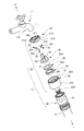
図1には、本考案に係る実施形態の蛇口用管継手10の分解斜視図が示されている。なお、以下の説明においては、図1に示すように、蛇口用管継手10の使用時における上方を「上」とし、下方を「下」として説明する。
DESCRIPTION OF EMBODIMENTS Hereinafter, faucet pipe joints according to embodiments of the present invention will be described with reference to the drawings.
FIG. 1 is an exploded perspective view of a
図1に示すように、蛇口用管継手10は、蛇口11に取り付けられるアダプタ20と、ホース12の先端に取り付けられてアダプタ20に切り離し可能に接続されるコネクタ40とを有する。したがって、蛇口用管継手10を蛇口11に取り付けた状態で、コネクタ40をアダプタ20から切り離すことにより、ホース12を蛇口11から外すことができる。
As shown in FIG. 1, the
図2(A)、(B)及び図3(A)にも示すように、アダプタ20は、上側に上蓋部材21を有し、下側に接続部22を有する。
上蓋部材21は全体扁平な円柱形状を呈しており、中央には、蛇口11の先端111(図1参照)が挿入される取付孔211が上下方向に貫通して形成されている。上蓋部材21の上面には、蛇口11に取り付けた際に、蛇口11の水平部112が嵌る凹部212が設けられており、アダプタ20が蛇口11に対して所定の取付位置からずれにくいようになっている。
As shown in FIGS. 2A, 2B, and 3A, the
The
さらに、上蓋部材21の上面には、部分円弧上の開口部213が2か所設けられている。一対の開口部213は、凹部212の中心線CLに対して対称位置に設けるのが望ましい。なお、開口部213は、3か所以上設けることも可能である。
また、上蓋部材21の下部は、外周面にねじが切られた雄ねじ部214が形成されている(図1参照)。
Further, two
Moreover, the
上蓋部材21の内部には、蛇口11を把持するためのロック爪25が複数個(ここでは、3個)設けられている。3個のロック爪25は、平面視で等間隔になるように、中心角120度で配置されている(図2(A)参照)。ロック爪25は、外側端部に設けられている揺動中心251を中心として、上蓋部材21に揺動可能に支持されている。
A plurality (three in this case) of
図3(B)に示すように、ロック爪25の内側端面252は、下方に向かって内側(上蓋部材21の中心側)に傾斜しており、揺動中心251から内側端面252の上端部253までの半径R1は、揺動中心251から内側端面252の下端部254までの半径R2よりも小さい。そして、内側端面252の上端部253は、アダプタ20を蛇口11に取り付ける際に、蛇口11に届かない位置に設け、内側端面252の下端部254は、蛇口11に届く位置に設ける。このため、アダプタ20を蛇口11に取り付ける際には、蛇口11の先端111が、内側端面252の途中位置に当接して、ロック爪25を下方へ揺動させる。また、ロック爪25の内側端面252は、水平方向に延びる山部及び谷部が上下方向に交互に形成されてギザギザ面となっている。
As shown in FIG. 3B, the
このため、ロック爪25が揺動中心251回りに下方から上方向へ揺動すると(図3(A)中矢印A参照)、内側端面252の上端部253は蛇口11に当接しないが、下端部254は当接するので、内側端面252の途中位置で蛇口11に当接することになる。このとき、内側端面252に設けられているギザギザの山が蛇口11に押し付けられるので、蛇口11をしっかりと把持することができる。
Therefore, when the
図2(B)及び図3(A)に示すように、接続部22は、接続部上部221と接続部下部222を有しており、全体T字形状に形成されている。
接続部上部221は円柱形状を呈しており、上端部には上蓋部材21の雄ねじ部214が嵌合する取付凹部226が形成されている。取付凹部226の外周面には、上蓋部材21の雄ねじ部214が螺合する雌ねじ部223が形成されている。また、接続部上部221の内部下端部には、接続部上部221の内面から一定距離で、低い係止壁224が全周にわたって設けられている。
As shown in FIGS. 2B and 3A, the
The connection portion
図3(A)に示すように、上蓋部材21の雄ねじ部214を接続部22の雌ねじ部223に螺合させて上蓋部材21を接続部22に取り付けると、アダプタ20の内部に空間(内部空間23)が形成される。
As shown in FIG. 3A, when the
この内部空間23には、最も下側に第1押圧部材24が設けられている。第1押圧部材24は、中央に円形の押圧部材開口部244(図1参照)が形成されたリング状を呈しており、外周部は下方に延びる外周壁241を有する。外周壁241は、接続部上部221の内面と係止壁224との間に、上下移動可能に挿嵌されている。また、第1押圧部材24の内側端部245は下方に曲げられて、下方のみが開口した第1水圧凹部242が形成されている。この第1押圧部材24の内側端部245の内面243は、弾性変形によってアダプタ20に挿入された蛇口11の先端111の外周面に密着する。第1押圧部材24は、ゴムや樹脂等の弾力性のある材料で形成することができる。
The
また、第1押圧部材24の上側には、第2押圧部材26が上下移動可能に設けられている。第2押圧部材26は、中央に円形のパッキン開口部264(図1参照)が形成された全体リング状を呈しており、内側端部261は下方に曲げられて、下方のみが開口した第2水圧凹部262が形成されている。この第2押圧部材26の内側端部261の内面263は、弾性変形によってアダプタ20に挿入された蛇口11の先端111の外周面に密着する。第2押圧部材26は、ゴムや樹脂等の弾力性のある材料で形成することができる。
A second pressing
さらに、第2押圧部材26の上側でロック爪25との間には、ロック解除部材30が、上下移動可能に設けられている。ロック解除部材30は、ロック爪25を押し上げて蛇口11を把持するように揺動させている第2押圧部材26及び第1押圧部材24を押し下げて、ロック爪25を下方(蛇口11を開放する方向)へ揺動可能にするための部材である。ロック解除部材30は、剛性の高い樹脂等で形成することができる。
Further, an
図4に示すように、ロック解除部材30は、円形の解除部材開口部33を有するリング形状の解除部材本体31と、解除部材本体31から上方に延びる複数個(ここでは、2個)の脚部32を有する。解除部材開口部33の内径は、パッキン開口部264の内径と等しいか若干小さめとなっている。また、脚部32の高さは、ロック爪25が蛇口11を把持している状態では、上蓋部材21の開口部213から先端部321が突出するようにする(図2(B)中二点鎖線で表示)。さらに、脚部32の高さは、脚部32の先端部321が上蓋部材21の上面から埋没したときには、ロック爪25が上下に揺動可能、すなわちロック解除となるように設定する。
As shown in FIG. 4, the
図2(B)及び図3(A)に示すように、接続部下部222は、接続部上部221の下側に設けられている小径部分であり、複数の凹凸が上下方向に交互に形成されている。凹部には、ゴム製のパッキンが取り付けられる。接続部下部222の先端には、供給された水を流す流路開口225が形成されている。
なお、コネクタ40については既によく知られているので詳述しないが、外ケース41(図1参照)を下方へ引き下げ、アダプタ20の接続部下部222を挿入した後に外ケース41を元に戻すことにより、アダプタ20に容易に接続することができる。
As shown in FIGS. 2B and 3A, the connection portion
The
アダプタ20の組立ては、まず、接続部22の内部に、第1押圧部材24及び第2押圧部材26を順に積層する。一方、上蓋部材21には、ロック解除部材30の脚部32の先端部321を上蓋部材21の開口部213に下から挿入し、ロック解除部材30の解除部材本体31をロック爪25に当接させる。この状態で、上蓋部材21の雄ねじ部214を接続部22の雌ねじ部223に螺合させて、アダプタ20を組み立てる。
In assembling the
次に、蛇口11に対する蛇口用管継手10の取付け・取外し動作について説明する。なお、コネクタ40には、予めホース12が取り付けられているものとする。
まず、蛇口11の先端111をアダプタ20の取付孔211に挿入する。これにより、蛇口11の先端面がロック爪25の上部又は内側端面252に当接するので、ロック爪25は下方へ揺動するとともに、ロック解除部材30、第2押圧部材26及び第1押圧部材24も下方へ移動する。
Next, the attachment / detachment operation of the faucet pipe joint 10 with respect to the
First, the
次いで、アダプタ20の流路開口225を手で塞いで、蛇口11を開ける。蛇口11から供給された水は、流路開口225が塞がれているので上方へ逆流し、第1押圧部材24の第1水圧凹部242に圧入する。これにより、第1押圧部材24は、上方へ押し上げられる。そして、第1押圧部材24を上方へすり抜けた水は、第2押圧部材26の第2水圧凹部262に圧入して、第2押圧部材26を押し上げる。
Next, the
これにより、ロック解除部材30が押し上げられ、ロック解除部材30の解除部材本体31を介してロック爪25が上方へ押し上げられて上方へ揺動(図3(A)中矢印A参照)する。これにより、ロック爪25の内側端面252が蛇口11に押し付けられ、蛇口11を把持して固定する。同時に、ロック解除部材30が上昇するので、ロック解除部材30の脚部32の先端部321が、上蓋部材21の開口部213から突出する。
なお、蛇口用管継手10にホース12が接続されている場合には、流路開口225を塞ぐ代わりにホース12を塞ぐことにより、蛇口用管継手10を蛇口11に固定することもできる。
Thereby, the
When the
一方、蛇口用管継手10を蛇口11から外す際には、上蓋部材21から上方へ突出している脚部32の先端部321を押し下げて、ロック解除部材30によって第2押圧部材26及び第1押圧部材24を押し下げる。これにより、上方へ押し付けられていたロック爪25が下方へ揺動可能となるので、蛇口用管継手10を引き下げて蛇口11から外すことができる。
On the other hand, when the faucet pipe joint 10 is removed from the
以上、説明した本実施形態の蛇口用管継手10では、蛇口11を取付孔211に挿入して、アダプタ20の流路開口225を塞いだ状態で蛇口11から給水する。これにより、その水圧で第1押圧部材24及び第2押圧部材26を上方へ移動させてロック爪25を上方へ揺動させ、ロック爪25によって蛇口11を挟んで固定するので、大きな力を必要とせず、また、道具等を必要とせずに、容易に蛇口用管継手10を蛇口11に取り付けることができる。
As described above, in the faucet pipe joint 10 of the present embodiment described above, the
また、第1押圧部材24及び第2押圧部材26をロック爪25から離反させるロック解除部材30を蛇口用管継手10に設けたので、ロック爪25を上方へ揺動させて蛇口11をロックしている第1押圧部材24及び第2押圧部材26をロック爪25から離反させることができる。これにより、ロック爪25が下方へ揺動可能となるので、容易にロックを解除することができ、蛇口用管継手10を蛇口11から容易に外すことができる。
Further, since the
また、本実施形態の蛇口用管継手10では、第2押圧部材26に当接する解除部材本体31から上方に延びる複数個の脚部32の先端部321が、ロック状態においては蛇口用管継手10から突出している。このため、蛇口用管継手10から突出した先端部321を押し込むことにより、第1押圧部材24及び第2押圧部材26をロック爪25から離反させることができ、蛇口用管継手10を容易に外すことができる。
Further, in the faucet pipe joint 10 of the present embodiment, the
さらに、蛇口11から給水しているときにホース12が詰まると、ホース12内の水圧が上昇して蛇口用管継手10を蛇口11から外す力が生じるが、蛇口用管継手10内部の水圧が上昇すると、第1押圧部材24及び第2押圧部材26のロック爪25を揺動させる力が上昇する。これにより、ロック爪25が蛇口11を挟む力が上昇するので、蛇口用管継手10は蛇口11にしっかりと固定され、外れるのを防止できる。
Further, if the
以上、本考案の蛇口用管継手10について、具体的な実施形態に基づいて説明してきたが、本考案は、前述した具体的な実施形態に限定されるものでなく、本考案の技術思想を逸脱しない範囲における様々な変形及び改良を行ってもよいことは言うまでもない。
例えば、前述した実施形態においては、蛇口用管継手10によってホース12を蛇口11に接続する場合について説明したが、ホースとホースとを接続する接手に適用することもできる。
The faucet pipe joint 10 of the present invention has been described based on the specific embodiments. However, the present invention is not limited to the specific embodiments described above, and the technical idea of the present invention is not limited thereto. It goes without saying that various modifications and improvements may be made without departing from the scope.
For example, in the above-described embodiment, the case where the
このように、技術思想を逸脱しない範囲における様々な変形や改良を行ったものも本考案の技術的範囲に含まれるものであり、そのことは、当業者にとって、実用新案登録請求の範囲の記載から明らかである。 As described above, various modifications and improvements that do not depart from the technical concept are also included in the technical scope of the present invention. It is clear from
10 蛇口用管継手
11 蛇口
12 ホース
20 アダプタ
211 取付孔
24 第1押圧部材(押圧部材)
25 ロック爪
26 第2押圧部材(押圧部材)
30 ロック解除部材
31 解除部材本体
32 脚部
40 コネクタ
10 faucet pipe joint 11
25
30
Claims (2)
前記アダプタの内部に、前記蛇口の先端を挿入する前記アダプタの取付孔の周囲に揺動可能に設けられた複数のロック爪と、前記ロック爪をロック側に押圧する押圧部材とを有し、
前記蛇口を前記取付孔に挿入して、前記アダプタの排水側又は前記コネクタを介して前記アダプタに接続されたホースを塞いだ状態で前記蛇口から給水することにより、その水圧で前記押圧部材を移動させて前記ロック爪を揺動させ前記蛇口を挟んで固定する蛇口用管継手であって、
前記アダプタに、前記押圧部材を前記ロック爪から離反させるロック解除部材を設けた蛇口用管継手。 An adapter attached to the faucet, and a connector attached to the tip of the hose and detachably connected to the adapter;
Inside the adapter, it has a plurality of lock claws provided around the mounting hole of the adapter for inserting the tip of the faucet, and a pressing member that presses the lock claw toward the lock side,
By inserting the faucet into the mounting hole and supplying water from the faucet in a state where the hose connected to the adapter is closed via the drain side of the adapter or the connector, the pressure member is moved by the water pressure. A faucet pipe joint that swings and locks the lock claw and sandwiches the faucet,
A faucet pipe joint in which the adapter is provided with a lock release member that separates the pressing member from the lock claw.
前記ロック解除部材は、前記押圧部材に当接する解除部材本体と、前記解除部材本体から前記ロック爪側に延びる複数個の脚部とを有し、
前記脚部の先端部は、ロック状態においては前記アダプタから押し出されて突出しており、
前記アダプタから突出した前記先端部を押し込むことにより前記押圧部材を前記ロック爪から離反させる蛇口用管継手。 The faucet pipe joint according to claim 1,
The lock release member has a release member main body that contacts the pressing member, and a plurality of legs that extend from the release member main body to the lock claw side,
The tip of the leg is protruded by being pushed out of the adapter in the locked state,
A tap joint for faucet that separates the pressing member from the lock claw by pushing in the tip portion protruding from the adapter.
Priority Applications (1)
| Application Number | Priority Date | Filing Date | Title |
|---|---|---|---|
| JP2017000368U JP3209887U (en) | 2017-01-30 | 2017-01-30 | Faucet fittings |
Applications Claiming Priority (1)
| Application Number | Priority Date | Filing Date | Title |
|---|---|---|---|
| JP2017000368U JP3209887U (en) | 2017-01-30 | 2017-01-30 | Faucet fittings |
Publications (1)
| Publication Number | Publication Date |
|---|---|
| JP3209887U true JP3209887U (en) | 2017-04-13 |
Family
ID=58505093
Family Applications (1)
| Application Number | Title | Priority Date | Filing Date |
|---|---|---|---|
| JP2017000368U Active JP3209887U (en) | 2017-01-30 | 2017-01-30 | Faucet fittings |
Country Status (1)
| Country | Link |
|---|---|
| JP (1) | JP3209887U (en) |
-
2017
- 2017-01-30 JP JP2017000368U patent/JP3209887U/en active Active
Similar Documents
| Publication | Publication Date | Title |
|---|---|---|
| US9714504B2 (en) | Bathtub drain and overflow kit | |
| US20120031515A1 (en) | Shutoff Valves for Fluid Conduit Connectors | |
| JP5054956B2 (en) | Pipe fitting | |
| JP5234646B2 (en) | Piping connection device | |
| KR20150101227A (en) | dual clamp | |
| JP4926566B2 (en) | Holder device for connecting water faucet and water supply hose | |
| JP3209887U (en) | Faucet fittings | |
| US10627032B2 (en) | Quick connection structure of faucet outlet pipe | |
| WO2017059818A1 (en) | Quick installation joint | |
| KR102130793B1 (en) | a joint for a faucet | |
| KR102084957B1 (en) | One-touch pipe fitting device | |
| KR101815801B1 (en) | Water tap | |
| KR200409053Y1 (en) | A pipe holding device | |
| KR20110002990A (en) | Pipe connecting apparatus using packing of hollow pipe type | |
| KR102410627B1 (en) | Socket Type Fitting device for Pipe Fittings | |
| TW201516302A (en) | Fast joint of cleaning device | |
| KR101473770B1 (en) | Fittings for Furniture | |
| KR100767068B1 (en) | Device for coupling of water supply hose in washing machine | |
| KR20070020861A (en) | Device for coupling of water supply hose in washing machine | |
| KR101274062B1 (en) | advanced structure of hose-coupling apparatus for water valve | |
| JP2006183422A (en) | Release for remote control, and drain plug device equipped therewith | |
| JP5712265B2 (en) | Pipe connection structure and water supply equipment | |
| JP6533154B2 (en) | Faucet connection fitting | |
| EP1409800A2 (en) | Self-aligning faucet retainers | |
| KR200401645Y1 (en) | Holder device for connection of a tap and water supply hose |
Legal Events
| Date | Code | Title | Description |
|---|---|---|---|
| R150 | Certificate of patent or registration of utility model |
Ref document number: 3209887 Country of ref document: JP Free format text: JAPANESE INTERMEDIATE CODE: R150 |
|
| R250 | Receipt of annual fees |
Free format text: JAPANESE INTERMEDIATE CODE: R250 |
|
| R250 | Receipt of annual fees |
Free format text: JAPANESE INTERMEDIATE CODE: R250 |