JP3206854U - Assembled furniture - Google Patents
Assembled furniture Download PDFInfo
- Publication number
- JP3206854U JP3206854U JP2016003638U JP2016003638U JP3206854U JP 3206854 U JP3206854 U JP 3206854U JP 2016003638 U JP2016003638 U JP 2016003638U JP 2016003638 U JP2016003638 U JP 2016003638U JP 3206854 U JP3206854 U JP 3206854U
- Authority
- JP
- Japan
- Prior art keywords
- assembly
- docking
- hole
- female
- pin
- Prior art date
- Legal status (The legal status is an assumption and is not a legal conclusion. Google has not performed a legal analysis and makes no representation as to the accuracy of the status listed.)
- Expired - Fee Related
Links
Images


Landscapes
- Assembled Shelves (AREA)
- Connection Of Plates (AREA)
- Furniture Connections (AREA)
- Cabinets, Racks, Or The Like Of Rigid Construction (AREA)
Abstract
【課題】組立て式家具を提供する。【解決手段】オスアセンブリ1を嵌合させる第1板P1とメスアセンブリ2を嵌合させる第2板P2とを有する家具本体を備える組立て式家具であって、オスアセンブリ1ではオスアセンブリ1の底面に沿って、同一に組み合わせる方向へ伸びるピンとドッキング部が間隔形成され、メスアセンブリ2ではメスアセンブリ2の上面に沿って、前記組み合わせる方向へ伸びる二つの組み合わせ穴が間隔形成され、また、少なくとも一つの組み合わせ穴をドッキング穴とし、前記ドッキング穴は側面が凹んで溝が形成され、他の組み合わせ穴は定位穴とし、オスアセンブリ1とメスアセンブリ2との係合固定によって第1板P1と第2板P2とを組み合わせて、組立時間を簡略化できることを特徴とする。【選択図】図2An assembly-type furniture is provided. An assembly-type furniture comprising a furniture body having a first plate P1 for fitting a male assembly 1 and a second plate P2 for fitting a female assembly 2, wherein the male assembly 1 has a bottom surface of the male assembly 1. A pin and a docking portion extending in the same combination direction are spaced along the upper surface of the female assembly 2, and two combination holes extending in the combination direction are spaced along the upper surface of the female assembly 2, and at least one The combination hole is a docking hole, the side surface of the docking hole is recessed and a groove is formed, the other combination hole is a fixed hole, and the first plate P1 and the second plate are engaged by fixing the male assembly 1 and the female assembly 2 to each other. In combination with P2, the assembly time can be simplified. [Selection] Figure 2
Description
本考案は、家具に関し、特に、迅速に組立てられる組立て式家具に関する。 The present invention relates to furniture, and more particularly, to assembled furniture that can be assembled quickly.
近年、輸送コストと組立てるコストを削減するため、例えば、机、椅子、棚などの組立て式家具が発達してきている。このような組立て式家具は利用者によって持ち帰って自らDIYで組み立てることができ、利用者に手作りの楽しさと達成感を感じさせることによって楽しませる。 In recent years, assembling furniture such as desks, chairs, and shelves has been developed to reduce transportation costs and assembly costs. Such prefabricated furniture can be taken home by the user and assembled in DIY, and can be enjoyed by making the user feel homemade fun and a sense of accomplishment.
しかしながら、組立て式家具は、ねじで各パーツを組み立てるため、組立てる時に、ドライバーを事前に用意しなければならない。組立の作業性が悪くなる。また、組立てる期間にドライバーでそれぞれのねじを別々に回して1つ1つ締める故、従来の組立て式家具は組立てるのに長い時間が必要となる。このため、従来の組立て式家具を改良する必要がある。 However, since assembled furniture assembles each part with screws, a driver must be prepared in advance when assembling. Assembling workability is deteriorated. In addition, since each screw is separately turned and tightened one by one with a screwdriver during the assembly period, the conventional assembly-type furniture requires a long time to assemble. For this reason, it is necessary to improve the conventional assembly-type furniture.
そこで、本考案の目的は、迅速に、そして、組立の作業の便利性が向上できる組立て式家具を提供することである。 Accordingly, an object of the present invention is to provide an assembly-type furniture that can improve the convenience of assembly work quickly and with ease.
前記の目的を達成するための技術的手段として、本考案はオスアセンブリを嵌合させる第1板とメスアセンブリを嵌合させる第2板とを有する家具本体を備える組立て式家具であって、前記オスアセンブリでは前記オスアセンブリの底面に沿って、同一に組み合わせる方向へ伸びるピンとドッキング部が間隔形成され、前記ドッキング部はドッキング延長部とフック部とを有し、前記フック部は前記ドッキング延長部のドッキング延長側の表面方向へ突起して形成され、前記メスアセンブリでは前記メスアセンブリの上面に沿って、前記組み合わせる方向へ伸びる二つの組み合わせ穴が間隔形成され、また、少なくとも一つの組み合わせ穴をドッキング穴とし、前記ドッキング穴は側面が凹んで溝が形成され、他の組み合わせ穴は定位穴とし、前記ピンと前記ドッキング部との間隔距離および前記定位穴と前記ドッキング穴との間隔距離を設けることによって、前記ピンと前記ドッキング部を前記定位穴と前記ドッキング穴とにそれぞれ対応させ、前記ピンが前記組み合わせる方向に沿って前記定位穴に挿入された後、前記ドッキング延長部の前記ドッキング延長側の表面を前記ドッキング穴の内周面に隣接させ、前記ドッキング部のフック部が前記ドッキング穴の溝に入ることで前記オスアセンブリと前記メスアセンブリとを係合固定させ、前記オスアセンブリと前記メスアセンブリとの係合固定によって前記第1板と前記第2板とを組み合わすことを特徴とする組立て式家具を提供する。 As a technical means for achieving the above object, the present invention is a prefabricated furniture comprising a furniture body having a first plate for fitting a male assembly and a second plate for fitting a female assembly, In the male assembly, a pin extending in the same combination direction and a docking portion are formed along the bottom surface of the male assembly, and the docking portion includes a docking extension portion and a hook portion, and the hook portion is a portion of the docking extension portion. In the female assembly, two combination holes extending in the combination direction are formed along the upper surface of the female assembly so as to be spaced apart from each other, and at least one combination hole is formed as a docking hole. The docking hole has a recessed side surface to form a groove, and the other combination holes are stereotactic holes. By providing an interval distance between the pin and the docking portion and an interval distance between the localization hole and the docking hole, the pin and the docking portion correspond to the localization hole and the docking hole, respectively, and the pin is combined After being inserted into the stereotactic hole along the direction, the docking extension side surface of the docking extension is adjacent to the inner peripheral surface of the docking hole, and the hook part of the docking part enters the groove of the docking hole. The male assembly and the female assembly are engaged and fixed, and the first plate and the second plate are combined by engaging and fixing the male assembly and the female assembly. I will provide a.
本考案の一つの実施例では、前記ピンがその長さが前記ドッキング部の長さより短いことを特徴とする組立て式家具を提供する。 In one embodiment of the present invention, there is provided a prefabricated furniture characterized in that the pin has a length shorter than that of the docking portion.
本考案の一つの実施例では、前記オスアセンブリが前記ピンと前記ドッキング部との間で固定穴を有し、ねじに貫通されて前記オスアセンブリを第1板に固定される組立て式家具を提供する。 In one embodiment of the present invention, there is provided a prefabricated furniture in which the male assembly has a fixing hole between the pin and the docking portion, and is penetrated by a screw to fix the male assembly to the first plate. .
本考案の一つの実施例では、前記メスアセンブリがメスアセンブリの左右側に二つの接続部を有し、この二つの接続部は貫通穴をそれぞれ有し、ねじに貫通されて前記メスアセンブリを第2板に固定される組立て式家具を提供する。 In one embodiment of the present invention, the female assembly has two connecting portions on the left and right sides of the female assembly, each of the two connecting portions has a through hole, and is penetrated by a screw to connect the female assembly. A prefabricated furniture fixed to two plates is provided.
本考案の一つの実施例では、前記フック部と前記溝とが同じ側に位置することを特徴とする組立て式家具を提供する。 In one embodiment of the present invention, an assembly type furniture is provided in which the hook portion and the groove are located on the same side.
本考案の一つの実施例では、前記メスアセンブリが一体形成されたものである組立て式家具を提供する。 In one embodiment of the present invention, a prefabricated furniture is provided in which the female assembly is integrally formed.
本考案の一つの実施例では、前記オスアセンブリが一体形成されたものである組立て式家具を提供する。 In one embodiment of the present invention, a prefabricated furniture in which the male assembly is integrally formed is provided.
本考案の一つの実施例では、前記定位穴が前記メスアセンブリの上表面から下表面までを貫通する穴である組立て式家具を提供する。 In one embodiment of the present invention, there is provided a prefabricated furniture in which the stereotaxic hole is a hole penetrating from the upper surface to the lower surface of the female assembly.
本考案の一つの実施例では、前記ドッキング穴が前記メスアセンブリの上表面から下表面までを貫通する穴である組立て式家具を提供する。 In one embodiment of the present invention, there is provided a prefabricated furniture in which the docking hole is a hole penetrating from the upper surface to the lower surface of the female assembly.
本考案の一つの実施例では、前記ピンがその断面が矩形である組立て式家具を提供する。 In one embodiment of the present invention, a prefabricated furniture is provided in which the pin has a rectangular cross section.
本考案に用いられている技術手段によって、第1板のオスアセンブリは第2板のメスアセンブリに直接に挿入でき、オスアセンブリとメスアセンブリとの係合固定によって、第1板と第2板とを組み合わせて、ねじを回す時間を大幅に減少させ、ほかの道具に頼らずに組立てられ、組立てに必要な時間を短縮させることで、組立作業の便利性が向上させられる。 According to the technical means used in the present invention, the male assembly of the first plate can be directly inserted into the female assembly of the second plate, and the first plate and the second plate can be connected by engaging and fixing the male assembly and the female assembly. In combination, the time for turning the screw is greatly reduced, the assembly is performed without relying on other tools, and the time required for the assembly is shortened, thereby improving the convenience of the assembly work.
以下、本考案を実施するための形態について、図1〜図5に基づいて説明する。この説明は本考案を限定するものではなく、本考案の一つの実施例にすぎない。 Hereinafter, the form for implementing this invention is demonstrated based on FIGS. This description is not intended to limit the invention but is only one embodiment of the invention.
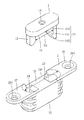
図1に示すように、本考案による実施例における組立て式家具は家具本体100を備え、家具本体100には第1板P1と第2板P2とを有し、第1板にはオスアセンブリ1が嵌合設置され、第2板にはメスアセンブリ2が嵌合設置される。オスアセンブリ1とメスアセンブリ2が一体成形ものであるのが好ましい。
As shown in FIG. 1, the assembling-type furniture according to the embodiment of the present invention includes a
図2〜図4に示すように、オスアセンブリ1には、オスアセンブリ1の下面から同じように組み合わせる方向Cに沿って伸びるピン12とドッキング部13が間隔を置いて設置される。すなわち、オスアセンブリ1の下面11にはピン12とドッキング部13とが間隔を置いて設置され、そのピン12とドッキング部13は同様に組み合わせる方向Cに向かって伸びる。本実施例において、ピン12の長さはドッキング部13の長さより短い。もちろん、本考案はこれに限定されるものではなくピン12の長さがドッキング部13の長さより長くても同じ長さでもよい。本実施例において、ピン12の断面は矩形である。もちろん、本考案はこれに限定されるものではなく、ピン12の断面が円形であることもできる。
As shown in FIGS. 2 to 4, the
ドッキング部13はドッキング延長部131とフック部132とを有する。フック部132はドッキング延長部131のドッキング延長側133の表面方向へ突起して形成される。詳しく説明すると、ドッキング延長側133はドッキング部13の内側に位置し、すなわち、フック部132はピン12の方向に向かって突起し、フック部132がドッキング部13の内側に位置される。もちろん、本考案はこれに限定されず、フック部132がピン12の方向の反対側に向かって突起し、ドッキング延長側133がドッキング部13の外側に位置することもできる。
The
オスアセンブリ1は、ピン12とドッキング部13との間に固定穴14を有し、ねじ15(図3に示すように)に貫通されることにより、オスアセンブリ1が第1板に固定されることが好ましい。
The
図2〜図5に示すように、メスアセンブリ2はメスアセンブリ2の上面21に沿って、組み合わせる方向Cへ伸びる二つの組み合わせ穴23、24が間隔を置いて形成され、この二つの組み合わせ穴23、24はメスアセンブリ2の上面21から下面22まで貫通する貫通穴である。具体的には、組み合わせ穴23、24はドッキング部13が挿入されるドッキング穴とし、ピン12が挿入される定位穴とする。すなわち、組み合わせ穴23、24のどちらも、ドッキング穴と定位穴の両方の役割を兼ね備えている。ドッキング穴は側面が凹んで溝231が形成され、その溝231とフック部132とは同じ側に位置し(図4に示すように)、ドッキング部13のフック部132が挿入されることに用いられる。本実施例において、組み合わせ穴24には溝231のサイズと同じ溝241が形成され(図5に示すように)、ドッキング部13のフック部132が挿入されることにより、オスアセンブリ1のドッキング部13はメスアセンブリ2の組み合わせ穴23、24のいずれかに任意に挿入でき、オスアセンブリ1とメスアセンブリ2との組立方式が多様化できる。
As shown in FIGS. 2 to 5, the
メスアセンブリ2がメスアセンブリ2の左右側に二つの接続部25、26を有する(図4に示すように)のが好ましい。二つの接続部25、26は貫通穴251、261をそれぞれ有し、ねじ15(図3に示すように)に貫通されて前記メスアセンブリ2が第2板P2に固定される。
The
ここでは説明のため、組み合わせ穴24を、ピン12が実際に挿入される定位穴とし、組み合わせ穴23を、ドッキング部13が実際に挿入されるドッキング穴として説明する。
図1〜図5に示すように、本実施例において、ピン12とドッキング部13との間隔距離D1および定位穴である組み合わせ穴24とドッキング穴である組み合わせ穴23との間隔距離D2を設けることによって、ピン12とドッキング部13を定位穴である組み合わせ穴24とドッキング穴である組み合わせ穴23とにそれぞれ対応させ、ピン12が組み合わせる方向Cに沿って定位穴である組み合わせ穴24に挿入された後、ドッキング延長部131のドッキング延長側133の表面をドッキング穴である組み合わせ穴23の内周面232に隣接させ、ドッキング13のフック部132がドッキング穴である組み合わせ穴23の溝231に入ることでオスアセンブリ1とメスアセンブリ2とを係合固定させ(図4に示すように)、オスアセンブリ1とメスアセンブリ2との係合固定によって第1板P1と第2板P2とを組み合わせる。
Here, for the sake of explanation, the
As shown in FIGS. 1 to 5, in this embodiment, a distance D <b> 1 between the
以上のように、オスアセンブリ1とメスアセンブリ2との係合固定によって第1板P1と第2板P2とを組み合わせることによって、利用者は家具本体(図1に示すように)の組立を簡単的に、かつスピーディに完成できる。
As described above, by combining the first plate P1 and the second plate P2 by engaging and fixing the
上記の説明はただ本考案の好ましいとされる実施例の説明である。この技術に対し、本考案の実用新案登録請求の範囲と上述の説明に基づいて、ほかの変更もできるが、これらの変更も本考案の創意であるべく、本考案の権利的範囲に包含される。 The above description is merely illustrative of the preferred embodiment of the present invention. Other modifications can be made to this technology based on the claims of the utility model registration of the present invention and the above description, but these modifications are also included in the scope of the present invention in order to be the originality of the present invention. The
100 家具本体
1 オスアセンブリ
11 下面
12 ピン
13 ドッキング部
131 ドッキング延長部
132 フック部
133 ドッキング延長側
14 固定穴
15 ねじ
2 メスアセンブリ
21 上面
22 下面
23、24 組み合わせ穴
231、241 溝
232 内周面
25 接続部
251 貫通穴
26 接続部
261 貫通穴
C 組み合わせる方向
D1 間隔距離
D2 間隔距離
P1 第1板
P2 第2板
DESCRIPTION OF
Claims (10)
前記オスアセンブリでは前記オスアセンブリの底面に沿って、同一に組み合わせる方向へ伸びるピンとドッキング部が間隔形成され、前記ドッキング部はドッキング延長部とフック部とを有し、前記フック部は前記ドッキング延長部のドッキング延長側の表面方向へ突起して形成され、
前記メスアセンブリでは前記メスアセンブリの上面に沿って、前記組み合わせる方向へ伸びる二つの組み合わせ穴が間隔形成され、また、少なくとも一つの組み合わせ穴をドッキング穴とし、前記ドッキング穴は側面が凹んで溝が形成され、他の組み合わせ穴は定位穴とし、
前記ピンと前記ドッキング部との間隔距離および前記定位穴と前記ドッキング穴との間隔距離を設けることによって、
前記ピンと前記ドッキング部を前記定位穴と前記ドッキング穴とにそれぞれ対応させ、
前記ピンが前記組み合わせる方向に沿って前記定位穴に挿入された後、前記ドッキング延長部の前記ドッキング延長側の表面を前記ドッキング穴の内周面に隣接させ、
前記ドッキング部のフック部が前記ドッキング穴の溝に入ることで前記オスアセンブリと前記メスアセンブリとを係合固定させ、
前記オスアセンブリと前記メスアセンブリとの係合固定によって前記第1板と前記第2板とを組み合わすこと
を特徴とする組立て式家具。 A prefabricated furniture comprising a furniture body having a first plate for fitting a male assembly and a second plate for fitting a female assembly,
In the male assembly, a pin extending in the same combination direction and a docking portion are formed at intervals along the bottom surface of the male assembly, the docking portion includes a docking extension portion and a hook portion, and the hook portion is the docking extension portion. It is formed by protruding toward the surface of the docking extension side of
In the female assembly, two combination holes extending in the combination direction are formed along the upper surface of the female assembly, and at least one combination hole is used as a docking hole, and the docking hole has a recessed side surface to form a groove. Other combination holes are stereotactic holes,
By providing an interval distance between the pin and the docking portion and an interval distance between the localization hole and the docking hole,
Making the pin and the docking part correspond to the localization hole and the docking hole, respectively;
After the pin is inserted into the stereotactic hole along the combination direction, the docking extension side surface of the docking extension is adjacent to the inner peripheral surface of the docking hole,
The hook part of the docking part enters the groove of the docking hole so that the male assembly and the female assembly are engaged and fixed,
A prefabricated furniture characterized by combining the first plate and the second plate by engaging and fixing the male assembly and the female assembly.
Applications Claiming Priority (2)
| Application Number | Priority Date | Filing Date | Title |
|---|---|---|---|
| TW105207538U TWM529434U (en) | 2016-05-23 | 2016-05-23 | Modular furniture |
| TW105207538 | 2016-05-23 |
Publications (1)
| Publication Number | Publication Date |
|---|---|
| JP3206854U true JP3206854U (en) | 2016-10-06 |
Family
ID=57047663
Family Applications (2)
| Application Number | Title | Priority Date | Filing Date |
|---|---|---|---|
| JP2016131524A Pending JP2017209475A (en) | 2016-05-23 | 2016-07-01 | Assembling-type furniture piece |
| JP2016003638U Expired - Fee Related JP3206854U (en) | 2016-05-23 | 2016-07-27 | Assembled furniture |
Family Applications Before (1)
| Application Number | Title | Priority Date | Filing Date |
|---|---|---|---|
| JP2016131524A Pending JP2017209475A (en) | 2016-05-23 | 2016-07-01 | Assembling-type furniture piece |
Country Status (2)
| Country | Link |
|---|---|
| JP (2) | JP2017209475A (en) |
| TW (1) | TWM529434U (en) |
Family Cites Families (4)
| Publication number | Priority date | Publication date | Assignee | Title |
|---|---|---|---|---|
| US4292003A (en) * | 1978-04-28 | 1981-09-29 | Underman Greeman Berger Limited | Connectors for furniture |
| JPS58186002U (en) * | 1982-06-05 | 1983-12-10 | 東罐興業株式会社 | Connecting device for plate-shaped bodies |
| JPS63125210U (en) * | 1987-02-09 | 1988-08-16 | ||
| JPH0342249Y2 (en) * | 1988-11-10 | 1991-09-04 |
-
2016
- 2016-05-23 TW TW105207538U patent/TWM529434U/en not_active IP Right Cessation
- 2016-07-01 JP JP2016131524A patent/JP2017209475A/en active Pending
- 2016-07-27 JP JP2016003638U patent/JP3206854U/en not_active Expired - Fee Related
Also Published As
| Publication number | Publication date |
|---|---|
| TWM529434U (en) | 2016-10-01 |
| JP2017209475A (en) | 2017-11-30 |
Similar Documents
| Publication | Publication Date | Title |
|---|---|---|
| US9771964B2 (en) | Fastening device, fastening system and furniture assembly | |
| US20120321378A1 (en) | Corner joint system for furniture panels | |
| JP5309330B2 (en) | drawer | |
| KR20140121496A (en) | Sectional desk | |
| US9829022B2 (en) | Universal joint system | |
| US20150021220A1 (en) | Tool box | |
| WO2017201769A1 (en) | Combination furniture | |
| KR102094641B1 (en) | 6-way connector modules | |
| JP3206854U (en) | Assembled furniture | |
| KR101925706B1 (en) | Assembly frame | |
| KR20170002615U (en) | Prefabricated wooden bookcase with metal parts | |
| JP3177219U (en) | Connecting means for prefabricated furniture | |
| CN103089771B (en) | T-shaped right angle connection piece of aluminium profile | |
| EP0056960B1 (en) | Joint for assembling panels | |
| TW201707613A (en) | Assemblable drawer for furniture and method for assembling the drawer | |
| KR20160001854U (en) | Assembly typer furniture | |
| KR20070105547A (en) | Assembly of binding knob for transmission lever unit | |
| KR200419194Y1 (en) | 220 Volt Outlet's Ground Terminal Structure | |
| JP3182149U (en) | Partition with connecting member | |
| JP3117060U (en) | Assembly furniture | |
| JP2012040219A (en) | Joint structure object | |
| KR200478005Y1 (en) | Knockdown angle connector of the furniture for ship | |
| KR20150074536A (en) | A modular furniture | |
| JP3198983U (en) | Storage cabinet | |
| JP3196064U (en) | Connecting means for prefabricated furniture |
Legal Events
| Date | Code | Title | Description |
|---|---|---|---|
| R150 | Certificate of patent or registration of utility model |
Ref document number: 3206854 Country of ref document: JP Free format text: JAPANESE INTERMEDIATE CODE: R150 |
|
| LAPS | Cancellation because of no payment of annual fees |