JP3202810U - Refractory powder filling machine for small electric furnace inner wall - Google Patents
Refractory powder filling machine for small electric furnace inner wall Download PDFInfo
- Publication number
- JP3202810U JP3202810U JP2015006264U JP2015006264U JP3202810U JP 3202810 U JP3202810 U JP 3202810U JP 2015006264 U JP2015006264 U JP 2015006264U JP 2015006264 U JP2015006264 U JP 2015006264U JP 3202810 U JP3202810 U JP 3202810U
- Authority
- JP
- Japan
- Prior art keywords
- refractory powder
- wall
- inner mold
- vibrators
- filling machine
- Prior art date
- Legal status (The legal status is an assumption and is not a legal conclusion. Google has not performed a legal analysis and makes no representation as to the accuracy of the status listed.)
- Active
Links
Images


Abstract
【課題】炉体における外壁と内型間の空間部に収容する耐火粉体を機械的に且つ短時間で高密度に充填し得る小型電気炉内壁用耐火粉体の充填機を提供する。【解決手段】エアー供給装置3からの高圧エアーによりピストン端部13がケーシング11外で出没するようにした2本1組のピストン式バイブレータ10,10を各ピストン端部13,13が相互に逆方向に出没し得る状態で取付台20に平面視平行姿勢で固定してなる打振装置1と、該打振装置1をその平面視中心位置を中心にして水平回転自在に吊持する吊持装置4とを有しているとともに、吊持装置4を支持して打振装置1を炉体の内型内に落とし込んだ状態で両バイブレータ10,10を作動させることで、各ピストン端部13,13が内型の内面を同時に打振するように構成した耐火粉体充填機Zを使用することにより、炉体内壁の元となる耐火粉体を機械的に高密度で充填し得るようにしている。【選択図】図1Disclosed is a refractory powder filling machine for a small electric furnace inner wall capable of mechanically filling a refractory powder accommodated in a space between an outer wall and an inner mold in a furnace body in a short time with high density. SOLUTION: A pair of piston vibrators 10 and 10 in which a piston end 13 protrudes and retracts outside a casing 11 by high-pressure air from an air supply device 3, and each piston end 13 and 13 are opposite to each other. And a suspension device 1 that is fixed to the mounting base 20 in a parallel posture in a plan view in a state where it can appear and disappear in a direction, and a suspension that suspends the vibration device 1 so as to be horizontally rotatable around the center position in the plan view. Each piston end portion 13 by operating both vibrators 10 and 10 while supporting the suspension device 4 and dropping the vibration device 1 into the inner mold of the furnace body. , 13 uses a refractory powder filling machine Z configured to vibrate the inner surface of the inner mold at the same time, so that the refractory powder that forms the wall of the furnace body can be filled mechanically at high density. ing. [Selection] Figure 1
Description
本願考案は、小型電気炉を築炉する際の、電気炉内壁の元となる耐火粉体を高密度に充填するための小型電気炉内壁用耐火粉体の充填機に関するものである。 The present invention relates to a refractory powder filling machine for a small electric furnace inner wall for high density filling of the refractory powder that is the base of the electric furnace inner wall when a small electric furnace is built.
電気炉は、主として炉内部で金属を熔融させるのに用いられる関係で、該電気炉の内壁は高耐熱仕様に形成する必要がある。 Since the electric furnace is mainly used for melting metal inside the furnace, the inner wall of the electric furnace needs to be formed to have a high heat resistance specification.
そして、電気炉の内壁は、一般に耐火粉体(シリカ粉)を高温度で焼結して形成されているが、該電気炉内壁の耐火度を高めるためには、焼結前に耐火粉体を高密度に充填しておくことが有効である。尚、このことは、電気炉が小型のものであっても同様である。 The inner wall of the electric furnace is generally formed by sintering a refractory powder (silica powder) at a high temperature. In order to increase the fire resistance of the inner wall of the electric furnace, the refractory powder before sintering is used. It is effective to fill with a high density. This is the same even if the electric furnace is small.
従来から小型電気炉の築炉方法は、一般に図5に示すように行われていた。即ち、図5に示す従来の築炉方法は、まず炉体5の外壁50の底壁部50a上に底面用の耐火粉体(シリカ粉)S1を所定厚さだけ投入して締め固めた後、外壁50内の中央部に内型(金属製)51を配置し(このとき内型51はスペーサーで位置保持させておく)、続いて外壁50の内側面と内型51の外側面との間の空間部52に耐火粉体S2〜S6を充填した状態で、加熱コイル53により耐火粉体(全体)Sを高温度(例えば1550〜1600℃)で加熱して焼結させることにより、高耐火度の内壁(焼結層)を構築するようにしている。尚、加熱コイル53で耐火粉体Sを焼結させるまで加熱すると、内部の内型(金属製)51も溶解するが、その溶解した金属溶湯は炉体5外に排出する。
Conventionally, a small electric furnace has been generally constructed as shown in FIG. That is, in the conventional furnace construction method shown in FIG. 5, first, a refractory powder (silica powder) S1 for the bottom surface is put into a predetermined thickness on the
ところで、図5の築炉方法において、炉体内壁の元となる耐火粉体Sは、外壁50と内型51との間の空間部52に高密度に充填するほど高耐火度の内壁(焼結層)を構築することができる。
By the way, in the furnace construction method of FIG. 5, the refractory powder S, which is the base of the furnace body wall, fills the
そして、従来では、炉体5の上記空間部52に耐火粉体Sを高密度で充填するのに、図5に示すように、外壁50と内型51との間の空間部52に耐火粉体を所定高さずつ(S2〜S6)分割して投入するとともに、その分割投入した各高さの耐火粉体S2〜S6ごとに炉体5の上方から突き棒Aで人手により突き固めるようにしている。この場合、複数人(小型の炉体5の場合は二人程度)で各高さS2〜S6部分をそれぞれ周方向に位置を変えながら突き固めていく。尚、このような突き棒Aによる耐火粉体の突き固め方法の従来例としては、例えば特開平5−272873号公報の図6(特許文献1)に開示されたものがある。
Conventionally, in order to fill the
ところが、図5の従来例のように、外壁50と内型51間の空間部52に順次投入される各高さの耐火粉体S2〜S6をそれぞれ人手により突き棒Aで突き固めるようにした耐火粉体充填方法では、次のような問題があった。
However, as in the conventional example of FIG. 5, the refractory powders S2 to S6 having respective heights that are sequentially put into the
即ち、上記空間部52に投入される各高さの耐火粉体S2〜S6ごとにしかも該空間部52の全周に亘って、それぞれ人手により突き棒Aで突き固めるようにしているので、その突き固め作業が非常に疲れる作業となるとともに、該空間部52の全高さ(S6の高さ)まで耐火粉体Sを充填するのに多大の時間が必要であった。
That is, since the refractory powders S2 to S6 of each height put into the
又、図5のように人手(突き棒A)による耐火粉体S2〜S6の突き固めでは、場所(高さ方向及び周方向の場所)によって耐火粉体の充填密度にバラツキが生じ易くなり、電気炉内壁の品質(耐火度や耐久性等)に難点が生じるおそれがあった。 Further, as shown in FIG. 5, in the tamping of the refractory powders S2 to S6 by hand (a thrust bar A), the filling density of the refractory powder tends to vary depending on the location (the location in the height direction and the circumferential direction). There was a risk of difficulty in the quality of the inner wall of the electric furnace (fire resistance, durability, etc.).
そこで、本願考案は、炉体における外壁と内型間の空間部に収容する耐火粉体を機械的に且つ短時間で高密度に充填し得るようにした小型電気炉内壁用耐火粉体の充填機を提供することを目的としてなされたものである。 Therefore, the present invention is designed to fill a refractory powder for a small electric furnace inner wall that can be mechanically and densely filled with the refractory powder accommodated in the space between the outer wall and the inner mold in the furnace body. It was made for the purpose of providing a machine.
本願考案は、上記課題を解決するための手段として次の構成を有している。尚、本願考案は、小型電気炉内壁用耐火粉体の充填機を対象にしているが、以下の説明では、本願考案の名称を単に耐火粉体充填機と称することがある。 The present invention has the following configuration as means for solving the above problems. Although the present invention is intended for a refractory powder filling machine for a small electric furnace inner wall, in the following description, the name of the present invention may be simply referred to as a refractory powder filling machine.
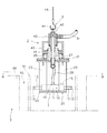
本願考案の耐火粉体充填機Zは、添付の図1〜図4に例示するように、炉体5の外壁50の内側面と該外壁50内に配置した内型51の外側面との間の空間部52に炉内面の耐火壁の元となる耐火粉体Sを高密度に充填するために使用されるものである。
The refractory powder filling machine Z of the present invention is, as illustrated in the attached FIGS. 1 to 4, between the inner side surface of the
そして、本願考案の耐火粉体充填機Zは、エアー供給装置3からの高圧エアーによりケーシング11内でピントン12が高速往復動してピストン端部13がケーシング11外で出没するようにした2本1組のピストン式バイブレータ10,10を各ピストン端部13,13が相互に逆方向に出没し得る状態で取付台20に平面視平行姿勢で固定してなる打振装置1と、該打振装置1をその平面視中心位置Pを中心にして水平回転自在に吊持する吊持装置4とを有しているとともに、該吊持装置4を支持して打振装置1を炉体5の内型51内に落とし込んだ状態で両バイブレータ10,10を作動させることで、各ピストン端部13,13が内型51の内面を同時に打振するように構成されていることを特徴とするものである。
The refractory powder filling machine Z of the present invention has two pieces in which the
尚、本願の文言中の「打振」とは、各バイブレータ10,10の各ピストン端部13,13で炉体5の内型51の内面を高速殴打して該内型51を高速振動(振動数が例えば1900〜2300/分)させることを意味するものである。
The term “vibration” in the wording of the present application means that the inner end of the
本願では、各バイブレータ10,10としてピストン式バイブレータが採用されているが、この各バイブレータ10,10の能力は、特に限定するものではないが例えば0.4〜0.6MPa程度のエアー圧を連続供給することで、振動数が1900〜2300回/分程度で振動力が280〜370N程度のものが適当である。尚、各側のピストン12,12のストロークは、25〜30mm程度でよい。
In the present application, piston type vibrators are employed as the
各バイブレータ10,10は、取付台20の同高さ位置において各ピストン端部13,13が相互に逆向きに出没する平行姿勢で、しかも取付台20に対してピストン出没方向に位置調整可能に設置されている。そして、この各バイブレータ10,10は、該両バイブレータ10,10の各ピストンがそれぞれ没入した状態での各側のピストン端部13,13を結ぶ仮想円が築炉すべき炉体5の内型51の内径よりよりやや小さくなる一方、各ピストンがそれぞれ突出した状態では各側のピストン端部13,13が上記内型51の対向する内面に同時に衝突するように位置設定される。
The
又、本願において、打振装置1の平面視中心位置Pとは、両バイブレータ10,10における各ピストン端部13,13を結ぶ仮想円の中心のことであり、この打振装置1の平面視中心位置Pを上記吊持装置4で水平回転自在に吊持している。従って、打振装置1を吊持装置4で吊持した状態では、上記平面視中心位置Pから各側のピストン端部13,13までの直線距離は常に等しくなる。
In addition, in the present application, the plan view center position P of the
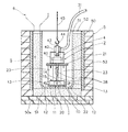
本願考案の耐火粉体充填機Zは、次のように使用される。まず、図4に示すように、炉体5の外壁50の底壁部50a上に底面用の耐火粉体(シリカ粉)S1を所定厚さだけ投入して締め固めた後、外壁50内の中央部に内型(金属製)51を配置し(該内型51をスペーサー等で位置決めしておく)、続いて外壁50の内側面と内型51の外側面との間の空間部52にシュート6を使用して耐火粉体Sを投入する。尚、このときの耐火粉体Sの投入は、空間部52の全高さ範囲に一気に投入してもよい。
The refractory powder filling machine Z of the present invention is used as follows. First, as shown in FIG. 4, after a predetermined thickness of refractory powder (silica powder) S <b> 1 for the bottom surface is placed on the
次に、耐火粉体充填機Zの吊持装置4部分を吊りフック44つきのロープ45で吊持して、打振装置1部分を内型51内の底部付近まで吊り降ろし(図4の状態)、その状態でエアー供給装置3(図1)からの高圧エアーを両バイブレータ10,10のケーシング11,11内に供給する。すると、各バイブレータ10,10のピストン端部13,13がそれぞれ同時に高速で出没し、その各ピストン端部13,13が外方に突出したときに該各ピストン端部が図3に符号13′,13′で示すように内型51の内面に同時に衝突して(出没を繰り返す)、該内型51の殴打部分を高速振動させるようになる。そして、該内型51が高速振動することにより、上記空間部52内の耐火粉体S2が高速で揺すられて高密度に締め固められるようになる。
Next, the
他方、両バイブレータ10,10の各ピストン端部13,13が内型51の対向する位置の内面に同時に衝突すると、各ピストン端部13,13の突出方向が内型51内周面の半径方向とは角度を持っているので、各ピストン端部13,13による衝突力によって打振装置1が吊持装置4(非回動)に対して1回当たりごく微小角度ずつ水平回転(図3の図示例では矢印R方向に回転)するようになり、各ピストン端部13,13による衝突位置が周方向に自動で刻々変化するようになる。
On the other hand, when the piston ends 13 and 13 of the
上記空間部52内の下方位置での耐火粉体の高密度充填操作が完了すると(打振装置1が少なくとも1/2回転した後)、耐火粉体充填機Zを所定高さ(例えば10〜20cm程度)だけ引き上げて、その高さにおいて打振装置1による上記同様の打振操作を行い、順次同様に空間部52内の最上段高さまで耐火粉体を高密度充填させる。尚、空間部52内の耐火粉体Sが振動で締め固められると該耐火粉体Sが沈降して嵩が低くなるので、その嵩が低くなった量の耐火粉体を空間部52内に補充する。
When the high-density filling operation of the refractory powder at the lower position in the
そして、空間部52の全高さ範囲に耐火粉体を高密度充填した後、加熱コイル53により耐火粉体(全体)Sを高温度(例えば1550〜1600℃)で加熱して焼結させることで、高耐火度の内壁(焼結層)を構築できる。尚、その高温度加熱時には、内部の内型(金属製)51も溶解するが、その溶解した金属溶湯は炉体5外に排出すればよい。
Then, after high density filling of the refractory powder in the entire height range of the
本願考案の耐火粉体充填機は、次のような効果がある。 The refractory powder filling machine of the present invention has the following effects.
まず、打振装置1部分を炉体5の内型51内に吊り降ろした状態で両バイブレータ10,10を作動させることにより、各ピストン端部13,13が内型51内面の対向位置を高速打振するので、外壁50と内型51間の空間部52に投入した耐火粉体を人手によらず機械的に高密度充填させることができる(作業員が疲れない)とともに、その充填作業時間を大幅に短縮できるという効果がある。
First, by operating both
又、打振装置1は取付台20に両バイブレータ10,10を平面視平行姿勢で固定している一方、該打振装置1の平面視中心位置Pを吊持装置4で水平回転自在に吊持しているので、打振装置1の各ピストン端部13,13が内型51内面の対向位置に同時に衝突することにより、該打振装置1が吊持装置4に対して自動で微小角度ずつ水平回転するようになる。従って、上記空間部52の周方向全域に亘って耐火粉体を自動で且つ均一に高密度充填できるという効果もある。
Further, the
以下、図1〜図4を参照して本願実施例の耐火粉体充填機(正式な考案の名称は小型電気炉内壁用耐火粉体の充填機)を説明する。 Hereinafter, the refractory powder filling machine (formally devised name is a refractory powder filling machine for the inner wall of a small electric furnace) will be described with reference to FIGS.
この実施例の耐火粉体充填機Zは、図1〜図3に示すように、2本1組のピストン式バイブレータ10,10を有した打振装置1と、その平面視中心位置Pを中心にして水平回転自在に吊持する吊持装置4と、打振装置1の各バイブレータ10,10に高圧エアーを供給するためのエアー供給装置3とを備えて構成されている。
1 to 3, the refractory powder filling machine Z according to this embodiment is centered on a vibration-damping
そして、この耐火粉体充填機Zにおける各装置部分の詳細説明は後述するが、この耐火粉体充填機Zは、図4に示すように、炉体5の外壁50と内型51間の空間部52に投入される耐火粉体S2〜S6を順次高密度に充填するものであって、打振装置1部分を吊持装置4で吊持して炉体5の内型51内に吊り降ろした状態で、各バイブレータ10,10を作動させることにより、各ピストン端部13,13で内型51内面の対向位置をそれぞれ高速打振することで、上記耐火粉体S2〜S6を上記空間部52内に順次高密度充填し得るようにしたものである。
A detailed description of each device portion in the refractory powder filling machine Z will be described later. This refractory powder filling machine Z is a space between the
耐火粉体充填機Zにおける打振装置1は、エアー供給装置3からの高圧エアーによりケーシング11内でピントン12が高速往復動してピストン端部13がケーシング11外で出没するようにした2本1組のピストン式バイブレータ10,10を使用しているとともに、該両バイブレータ10,10を取付台20に取付けたものである。
The
各バイブレータ10,10には、ピストン式バイブレータが採用されているが、この各バイブレータ10,10の能力は、特に限定するものではないが例えば0.4〜0.6MPa程度のエアー圧を連続供給することで、振動数が1900〜2300回/分程度で振動力が280〜370N程度のものが適当である。尚、各側のバイブレータ10,10のピストンストロークは、25〜30mm程度でよい。
Piston vibrators are used for the
打振装置1の取付台20は、円形の上部台板21と矩形の下部台板22とを上下に適宜高さを有した2枚1組の板状スペーサー23,23で一体化させたものである。
The mounting
そして、上記両バイブレータ10,10は、図1及び図3に示すように、下部台板22上の同高さ位置において各ピストン端部13,13が相互に逆向きに出没する平行姿勢で、しかも下部台板22に対してピストン出没方向に位置調整可能に設置されている。尚、各バイブレータ10,10の位置調整は、下部台板22の対向する各外端縁にそれぞれ立設した各側板24,24に止めボルト25,25を螺合しておき、該止めボルト25,25を緩めることで各バイブレータ10,10の各ケーシング11,11をピストン出没方向に移動調整できるとともに、該各バイブレータ10,10を位置調整した状態で各側の止めボルト25,25を締め込むことで各ケーシング11,11をそれぞれスペーサー23,23に押付けて各バイブレータ10,10を固定し得るようになっている。
And as shown in FIG.1 and FIG.3, the said
各バイブレータ10,10は、該両バイブレータ10,10の各ピストン12,12がそれぞれ没入した状態(図3の実線図示状態)での各側のピストン端部13,13を結ぶ仮想円が築炉すべき炉体5の内型51の内径よりよりやや小さくなる一方、各ピストンがそれぞれ突出した状態では各側のピストン端部13,13が上記内型51の対向する内面に同時に衝突する(図3の符号13′,13′の状態)ように位置設定される。尚、両バイブレータ10,10の下部台板22上での位置設定は、築炉対象となる炉体5の内型51の内径に対応して設定される。
Each of the
この打振装置1は、その平面視中心位置P(図3参照)を中心にして上記吊持装置4(詳細は後述する)で水平回転自在に吊持しているが、打振装置1の平面視中心位置P(図3参照)とは、両バイブレータ10,10における各ピストン端部13,13を結ぶ仮想円の中心のことである。従って、打振装置1を吊持装置4で吊持した状態では、上記平面視中心位置Pから各側のピストン端部13,13までの直線距離は常に等しくなる。
The
打振装置1側の上部台板21の上面には、打振装置1の平面視中心位置Pと同軸心の軸体26が立設固定されている。この軸体26内には、ロータリージョイント42を介してエアー供給装置3のエアー供給管31に連続するエアー通路27が形成されている。又、軸体26内のエアー通路27の下方には、2本の分岐管28,28が接続されていて、該分岐管28,28を介してそれぞれのバイブレータ10,10に高圧エアーを供給し得るようになっている。
On the upper surface of the
エアー供給装置3は、図1に示すように、エアー源(コンプレッサー)30からの高圧エアーをエアー供給管31を通して各バイブレータ10,10に供給するものであるが、エアー供給管31の途中には流量調整弁32と切換弁33が設けられている。流量調整弁32はエアー圧を例えば0.4MPaと0.6MPaに切換えるもので、切換弁33はエアーの供給をON・OFFするものである。尚、切換弁33は手動弁(図示例のもの)でもよいし電磁弁でもよい。
As shown in FIG. 1, the
尚、この実施例で採用している各バイブレータ10,10は、エアー供給口14から導入された高圧エアーでピストン12を突出方向に移動させた後、該高圧エアーがピストン12内を通ってエアー排出口15から排出されたときに、該ピストン12が没入方向に移動するように作動するものであって、そのピストン出没動作は極めて高速で行われる(振動数が例えば1900〜2300回/分)。
The
上記吊持装置4は、図1及び図2に示すように、打振装置1側の軸体26を囲う外筒40と、該外筒40を保持する保持枠43と、該保持枠43を吊持する吊りフック44付きのロープ45を有している。
As shown in FIGS. 1 and 2, the
そして、吊持装置4による打振装置1の吊持構造は、図2に示すように、打振装置1側の軸体26と吊持装置4側の外筒40との間にベアリング41を介設することにより、打振装置1を吊持装置4で水平回転自在に吊持し得るようにしている。尚、打振装置1は、その平面視中心位置Pと同軸の軸体26を中心にして水平回転するので、各側のピストン端部13,13の周方向への移動軌跡は同一円周上を移動することになる。
As shown in FIG. 2, the suspension structure of the
本願実施例の耐火粉体充填機Zは、次のように使用される。まず、図4に示すように、炉体5の外壁50の底壁部50a上に底面用の耐火粉体(シリカ粉)S1を所定厚さだけ投入して締め固めた後、外壁50内の中央部に内型(金属製)51を配置し(該内型51をスペーサー等で位置決めしておく)、続いて外壁50の内側面と内型51の外側面との間の空間部52にシュート6を使用して耐火粉体Sを投入する。尚、このときの耐火粉体Sの投入は、空間部52の全高さ範囲に一気に投入してもよい。
The refractory powder filling machine Z of the present embodiment is used as follows. First, as shown in FIG. 4, after a predetermined thickness of refractory powder (silica powder) S <b> 1 for the bottom surface is placed on the
次に、耐火粉体充填機Zの吊持装置4部分を吊りフック44付きのロープ45で吊持して、打振装置1部分を内型51内の底部付近まで吊り降ろし(図4の状態)、その状態でエアー供給装置3(図1)からの高圧エアーを両バイブレータ10,10に供給する。すると、各バイブレータ10,10のピストン端部13,13がそれぞれ同時に高速で出没し、その各ピストン端部13,13が外方に突出したときに該各ピストン端部が図3に符号13′,13′で示すように内型51の内面に同時に衝突して(出没を繰り返す)、該内型51の打振部分を高速振動させるようになり、該内型51が高速振動することにより、上記空間部52内の耐火粉体S2が高速で揺すられて高密度に締め固められるようになる。
Next, the
他方、両バイブレータ10,10の各ピストン端部13,13が内型51の対向する位置の内面に同時に衝突すると、各ピストン端部13,13による衝突力によって打振装置1が吊持装置4(非回動)に対して1回当たりごく微小角度ずつ水平回転(図3の矢印R方向に回転)するようになり、各ピストン端部13,13による衝突位置が周方向に自動で刻々変化するようになる。
On the other hand, when the piston ends 13 and 13 of the
上記空間部52内の下方位置での耐火粉体の高密度充填操作が完了すると(打振装置1が少なくとも1/2回転した後)、耐火粉体充填機Zを所定高さ(例えば10〜20cm程度)だけ引き上げて、その高さにおいて打振装置1による上記同様の打振操作を行い、順次同様に空間部52内の最上段高さまで耐火粉体を高密度充填させる。尚、空間部52内の耐火粉体Sが振動で締め固められると該耐火粉体Sが沈降して嵩が低くなるので、その嵩が低くなった量の耐火粉体を空間部52内に補充する。
When the high-density filling operation of the refractory powder at the lower position in the
そして、空間部52の全高さ範囲に耐火粉体を高密度充填した後、加熱コイル53により耐火粉体(全体)Sを高温度(例えば1550〜1600℃)で加熱して焼結させることで、高耐火度の内壁(焼結層)を構築できる。尚、その高温度加熱時には、内部の内型(金属製)51も溶解するが、その溶解した金属溶湯は炉体5外に排出すればよい。
Then, after high density filling of the refractory powder in the entire height range of the
このように、本願実施例の耐火粉体充填機では、打振装置1部分を炉体5の内型51内に吊り降ろした状態で両バイブレータ10,10を作動させることにより、各ピストン端部13,13が内型51内面の対向位置を高速打振するので、外壁50と内型51間の空間部52に投入した耐火粉体を人手によらず機械的に高密度充填させることができる(作業員が疲れない)とともに、その充填作業時間を大幅に短縮できるという効果がある。
As described above, in the refractory powder filling machine according to the embodiment of the present invention, each vibrator end portion is operated by operating both
又、打振装置1は取付台20(下部台板22)上に両バイブレータ10,10を平面視平行姿勢で固定している一方、該打振装置1の平面視中心位置Pを吊持装置4で水平回転自在に吊持しているので、打振装置1の各ピストン端部13,13が内型51内面の対向位置に同時に衝突することにより、該打振装置1が吊持装置4に対して自動で微小角度ずつ水平回転(図3の矢印R方向に回転)するようになる。従って、上記空間部52の周方向全域に亘って耐火粉体を自動で且つ均一に高密度充填できるという効果もある。
Further, the
1は打振装置、3はエアー供給装置、4は吊持装置、5は炉体、10はバイブレータ、11はケーシング、12はピストン、13はピストン端部、20は取付台、22は下部台板、50は外壁、51は内型、Pは平面視中心位置、Zは耐火粉体充填機である。
DESCRIPTION OF
Claims (1)
エアー供給装置(3)からの高圧エアーによりケーシング(11)内でピントン(12)が高速往復動してピストン端部(13)がケーシング(11)外で出没するようにした2本1組のピストン式バイブレータ(10,10)を上記各ピストン端部(13,13)が相互に逆方向に出没し得る状態で取付台(20)に平面視平行姿勢で固定してなる打振装置(1)と、該打振装置(1)をその平面視中心位置(P)を中心にして水平回転自在に吊持する吊持装置(4)とを有しているとともに、
上記吊持装置(4)を支持して上記打振装置(1)を上記炉体(5)の上記内型(51)内に落とし込んだ状態で上記両バイブレータ(10,10)を作動させることで、上記各ピストン端部(13,13)が上記内型(51)の内面を同時に打振するように構成されている、
ことを特徴とする小型電気炉内壁用耐火粉体の充填機。 The space (52) between the inner side surface of the outer wall (50) of the furnace body (5) and the outer side surface of the inner mold (51) disposed in the outer wall (50) serves as the source of the fire wall on the furnace inner surface. A refractory powder filling machine for an inner wall of a small electric furnace for densely filling the refractory powder (S) in a state of containing the refractory powder (S),
High pressure air from the air supply device (3) causes the pinton (12) to reciprocate at high speed in the casing (11) so that the piston end (13) protrudes and retracts outside the casing (11). A striking device (1) in which a piston type vibrator (10, 10) is fixed to a mounting base (20) in a parallel posture in plan view in a state where the piston end portions (13, 13) can protrude and retract in opposite directions. ) And a suspension device (4) that suspends the vibration device (1) so as to be horizontally rotatable around its center position (P) in plan view,
The vibrators (10, 10) are actuated while supporting the suspension device (4) and dropping the vibration device (1) into the inner mold (51) of the furnace body (5). The piston end portions (13, 13) are configured to simultaneously vibrate the inner surface of the inner mold (51).
A refractory powder filling machine for the inner wall of a small electric furnace.
Priority Applications (1)
| Application Number | Priority Date | Filing Date | Title |
|---|---|---|---|
| JP2015006264U JP3202810U (en) | 2015-12-11 | 2015-12-11 | Refractory powder filling machine for small electric furnace inner wall |
Applications Claiming Priority (1)
| Application Number | Priority Date | Filing Date | Title |
|---|---|---|---|
| JP2015006264U JP3202810U (en) | 2015-12-11 | 2015-12-11 | Refractory powder filling machine for small electric furnace inner wall |
Publications (1)
| Publication Number | Publication Date |
|---|---|
| JP3202810U true JP3202810U (en) | 2016-02-25 |
Family
ID=55360998
Family Applications (1)
| Application Number | Title | Priority Date | Filing Date |
|---|---|---|---|
| JP2015006264U Active JP3202810U (en) | 2015-12-11 | 2015-12-11 | Refractory powder filling machine for small electric furnace inner wall |
Country Status (1)
| Country | Link |
|---|---|
| JP (1) | JP3202810U (en) |
Cited By (2)
| Publication number | Priority date | Publication date | Assignee | Title |
|---|---|---|---|---|
| CN110173995A (en) * | 2019-06-06 | 2019-08-27 | 山东凯翔传热科技有限公司 | Pneumatic furnace ramming machine automatic regulating system and its implementation |
| US11400043B2 (en) | 2019-12-10 | 2022-08-02 | Mary Kay Inc. | Cosmetic composition |
-
2015
- 2015-12-11 JP JP2015006264U patent/JP3202810U/en active Active
Cited By (3)
| Publication number | Priority date | Publication date | Assignee | Title |
|---|---|---|---|---|
| CN110173995A (en) * | 2019-06-06 | 2019-08-27 | 山东凯翔传热科技有限公司 | Pneumatic furnace ramming machine automatic regulating system and its implementation |
| CN110173995B (en) * | 2019-06-06 | 2024-02-20 | 山东凯翔传热科技有限公司 | Automatic regulating system of pneumatic furnace building machine and implementation method thereof |
| US11400043B2 (en) | 2019-12-10 | 2022-08-02 | Mary Kay Inc. | Cosmetic composition |
Similar Documents
| Publication | Publication Date | Title |
|---|---|---|
| US11148368B2 (en) | Apparatus for additive manufacturing and use of the apparatus | |
| JP3202810U (en) | Refractory powder filling machine for small electric furnace inner wall | |
| CN106079432A (en) | Add and manufacture Apparatus and method for | |
| KR20040111350A (en) | A dynamic forging impact energy retention machine | |
| CN207435519U (en) | For the equipment of filtering metal | |
| JP2015057294A (en) | Method and device for producing metal component using casting-and-forming tool | |
| JP2009049202A5 (en) | ||
| Savelov et al. | Peculiarities of vibrational press dynamics with hard-elastic restraints in the working regime of metal powders molding | |
| CN207765566U (en) | Battery core immersion equipment | |
| JP2000301317A (en) | Dropping device of molding sand from casting | |
| US4140744A (en) | Method of molding products from moist materials and apparatus realizing same | |
| CN210045990U (en) | Isostatic pressing electromagnetism vibrations formula charging devices | |
| US4534730A (en) | Method of and apparatus for forming a liner in a furnace or other vessel | |
| CN207647183U (en) | A kind of vibrational structure for constructional column | |
| CN213496365U (en) | A sand case for vacuum full mold casting for producing wear-resisting return bend of bimetal | |
| US6743382B2 (en) | Method of installing a refractory lining | |
| US2799905A (en) | Machine for casting straps and posts onto groups of insulated battery plates | |
| KR20110007939U (en) | A disappearance model casting for dry sand filling system has the filling function even | |
| JPH09303969A (en) | Detachable crucible type melting furnace | |
| JP2020201002A (en) | Vibration tool for stamp application | |
| KR101918360B1 (en) | Mold support device for uniform vitrified form and forming method uniform vitrified form using in the same | |
| KR20020032210A (en) | the equipment and method foaming of ball ceramic | |
| CN210346331U (en) | External vibrating device for refractory material mould | |
| CN205614808U (en) | Brick machine | |
| TWI616253B (en) | Electrode unit, electric arc unit, and rotating electrode system |
Legal Events
| Date | Code | Title | Description |
|---|---|---|---|
| R150 | Certificate of patent or registration of utility model |
Ref document number: 3202810 Country of ref document: JP Free format text: JAPANESE INTERMEDIATE CODE: R150 |
|
| R250 | Receipt of annual fees |
Free format text: JAPANESE INTERMEDIATE CODE: R250 |