JP3202575U - Toy using ultrasonic linear motor - Google Patents
Toy using ultrasonic linear motor Download PDFInfo
- Publication number
- JP3202575U JP3202575U JP2015006040U JP2015006040U JP3202575U JP 3202575 U JP3202575 U JP 3202575U JP 2015006040 U JP2015006040 U JP 2015006040U JP 2015006040 U JP2015006040 U JP 2015006040U JP 3202575 U JP3202575 U JP 3202575U
- Authority
- JP
- Japan
- Prior art keywords
- linear motor
- ultrasonic linear
- toy
- ultrasonic
- ship
- Prior art date
- Legal status (The legal status is an assumption and is not a legal conclusion. Google has not performed a legal analysis and makes no representation as to the accuracy of the status listed.)
- Expired - Fee Related
Links
Images


Landscapes
- Toys (AREA)
Abstract
【課題】簡単な構成で方向転換を容易に行うことができる超音波リニアモータを用いた玩具を提供することを目的とする。【解決手段】船体6と、船体6の底部に設置され、船体6を走行駆動する2個の超音波リニアモータユニット2と、超音波リニアモータユニット2に電力を供給する電池4と、を有し、2個の超音波リニアモータユニット2が、船体6の走行方向の中心軸に対して左右対称に設置されていることを特徴とする超音波リニアモータを用いた玩具。【選択図】図1An object of the present invention is to provide a toy using an ultrasonic linear motor that can easily change the direction with a simple configuration. SOLUTION: A hull 6, two ultrasonic linear motor units 2 that are installed at the bottom of the hull 6 and drive the hull 6, and a battery 4 that supplies power to the ultrasonic linear motor unit 2 are provided. A toy using an ultrasonic linear motor, wherein two ultrasonic linear motor units 2 are installed symmetrically with respect to the central axis of the hull 6 in the traveling direction. [Selection] Figure 1
Description
本考案は、2つの超音波リニアモータを用いた方向転換が容易な玩具に関する。 The present invention relates to a toy that uses two ultrasonic linear motors and is easy to change direction.
現在、超音波振動子や超音波リニアモータを用いた玩具が、種々提案されている。例えば、特許文献1には本出願人が提案したリアクションホイールによって進行方向を制御する玩具に関する技術が開示されている。特許文献1の玩具につき、図6を参照しつつ以下に説明する。図6(a)は特許文献1の船舶玩具50を示す平面図、図6(b)は断面正面図である。
Currently, various toys using ultrasonic transducers and ultrasonic linear motors have been proposed. For example, Patent Document 1 discloses a technique related to a toy that controls the traveling direction using a reaction wheel proposed by the present applicant. The toy of Patent Document 1 will be described below with reference to FIG. 6A is a plan view showing the
船舶玩具50の船底部の中央には、駆動子20aを有する超音波リニアモータユニット2が固定ネジ59によって固定されている。超音波リニアモータユニット2は、船舶玩具50を走行駆動させる。超音波リニアモータユニット2の上方には、リアクションホイール60が取り付けられたモータ63が固定座66aを介して船体66に設置されている。リアクションホイール60の回転軸は鉛直方向を向いている。船体66の後方には、電池4が電池ケース5に収納されている。電池4は、超音波リニアモータユニット2とモータ63を駆動するための電力を供給する。船舶玩具50は、リアクションホイール60を回転させることでその進行方向を制御することができる。
An ultrasonic
しかし、上記した玩具では方向転換のためリアクションホイール60を用いるため、その構造が複雑であり多くのコストを要していた。
However, in the toy described above, the
本考案は上記課題を解決するためになされたものであり、簡単な構成で方向転換を容易に行うことができる超音波リニアモータを用いた玩具を提供することを目的とする。 The present invention has been made to solve the above-described problem, and an object thereof is to provide a toy using an ultrasonic linear motor that can easily change the direction with a simple configuration.
本考案は上記課題を解決するためになされたものであり、以下の構成を有する。 The present invention has been made to solve the above problems, and has the following configuration.
(1)筐体と、
前記筐体の底部に設置され、前記筐体を走行駆動する2個の超音波リニアモータと、
前記超音波リニアモータに電力を供給する電力共有手段と、を有し、
前記2個の超音波リニアモータが、前記筐体の走行方向の中心軸に対して左右対称に設置されていることを特徴とする超音波リニアモータを用いた玩具。
(1) a housing;
Two ultrasonic linear motors installed at the bottom of the housing and driving the housing;
Power sharing means for supplying power to the ultrasonic linear motor,
A toy using an ultrasonic linear motor, wherein the two ultrasonic linear motors are installed symmetrically with respect to a central axis in a traveling direction of the casing.
(2)前記筐体が、船体模型又は水鳥模型の筐体のいずれかであることを特徴とする前記(1)記載の超音波リニアモータを用いた玩具。 (2) The toy using the ultrasonic linear motor according to (1), wherein the casing is either a hull model or a waterfowl model casing.
(3)外部からの信号を受信するための受信手段を有し、
前記受信手段が受信した信号に基づいて、前記超音波リニアモータの駆動が制御されることを特徴とする前記(1)又は(2)に記載の超音波リニアモータを用いた玩具。
(3) having receiving means for receiving an external signal;
The toy using the ultrasonic linear motor according to (1) or (2), wherein driving of the ultrasonic linear motor is controlled based on a signal received by the receiving means.
本考案によれば、簡単な構成で方向転換を容易に行うことができる超音波リニアモータを用いた玩具を提供することができる。 ADVANTAGE OF THE INVENTION According to this invention, the toy using the ultrasonic linear motor which can perform direction change easily with a simple structure can be provided.
以下、本考案を実施するための形態を、図面を参照しつつ以下に説明する。 DESCRIPTION OF EMBODIMENTS Hereinafter, embodiments for carrying out the present invention will be described with reference to the drawings.
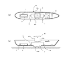
本実施例の超音波リニアモータを用いた船舶玩具10を図1に示す。図1(a)は船舶玩具10を上方から見た平面図であり、図1(b)は断面図、図1(c)は底面図である。図1(a)に示したように、筐体である船体6の略中央に超音波リニアモータユニット2が2個並列に、かつ筐体6の進行方向の中心軸に対して対称に設置されている。2個の超音波リニアモータユニット2を有することで、進行方向の制御が可能となる。超音波リニアモータユニット2は、底部に駆動素子20aを有している。船舶玩具10の進行方向の制御については、後に述べる。
A
電池ケース5に収納された電池4(電力供給手段)は、超音波リニアモータユニット2と制御基板7に電力を供給する。制御基板7は超音波リニアモータユニット2の動作を制御するものであり、後述するリモートコントローラ30(図3参照)からの信号を受信するための赤外線受光素子7aを有している。赤外線受光素子7aは電波受信素子であってもよい。電源スイッチ8は、船舶玩具10全体の電源をオン/オフするためのスイッチである。
A battery 4 (power supply means) housed in the
[超音波リニアモータユニット]
上記した超音波リニアモータユニット2について以下に説明する。まず、超音波リニアモータの動作原理について図2(a)〜(g)を用いて説明する。
[Ultrasonic linear motor unit]
The ultrasonic
超音波リニアモータは、弾性体の振動子に分極処理された圧電セラミックを接合し、その圧電セラミックを超音波振動による固有振動で共振させ、その振動方向を直接推力に変換させるものである。この圧電セラミック22は、電圧を付加すると図2(a)〜(c)のように伸び縮みするという性質がある。図2(a)は圧電セラミック22に電圧が付加されていない状態を示しており、図2(b)は圧電セラミック22の内部電荷と同一の電荷を付加した場合を示している。図2(b)の状態では、圧電セラミック22の内部電荷と外部電荷が斥け合うため、圧電セラミック22は縮んだ状態となる。図2(c)は圧電セラミック22の内部電荷と反対の電荷を付加した場合を示しており、内部電荷と外部電荷が引き合って圧電セラミック22は伸びた状態となる。
In the ultrasonic linear motor, a piezoelectric ceramic that has been subjected to polarization treatment is bonded to an elastic vibrator, the piezoelectric ceramic is resonated by natural vibration caused by ultrasonic vibration, and the vibration direction is directly converted into thrust. The
図2(d)、(e)に示したように、圧電セラミック22を金属製弾性体20に貼り合わせて電圧を付加すると、金属製弾性体20は微小な曲げ運動を行う。そして、金属製弾性体22の所定の位置に駆動子20aを形成する(図2(f))と、駆動子20aは図2(g)のように運動する。図2(g)のAの場合、駆動子20aは中線から上部、Cの場合、駆動子20aは中線から下部になる。駆動子20aの運動の力の大きさを縦のベクトル成分と横のベクトル成分に分けてみると、横方向のベクトル成分が物体を移動させる力となる。つまり、AとBとの間の距離が移動量となる。
As shown in FIGS. 2D and 2E, when the piezoelectric ceramic 22 is bonded to the metal
次に、本実施例の船舶玩具10で用いる超音波リニアモータユニット2を図2(h)に示す。超音波リニアモータユニット2は、上記した圧電セラミック22と金属製弾性体20、及び直流を交流に変換する駆動回路が収納ケース2cに収納されており、収納ケース2cは取付穴2dを2個有している。また、金属製弾性体20は駆動子20aを2個有しており、駆動子20aの先端が船舶玩具10が走行する走行面に接触する。
Next, the ultrasonic
[リモートコントローラ]
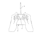
本実施例の船舶玩具10を制御するためのリモートコントローラについて説明する。リモートコントローラ30を操作している状態を図3に示す。リモートコントローラ30は、赤外線信号や無線信号等の制御信号を送信する。図3のリモートコントローラ30は、無線信号を送信するコントローラを示している。リモートコントローラ30のジョイスティック左31は船舶玩具10の前後方向の動きを制御するためのスイッチであり、ジョイスティック右32は船舶玩具10の左右方向の動きを制御するためのスイッチである。ジョイスティック左31を前方に倒すと船舶玩具10は前進し、後方に倒すと船舶玩具10は停止する。また、船舶玩具10が前進状態で、ジョイスティック右32を右側に倒すと船舶玩具10は右方向に曲がり、ジョイスティック右32を左側に倒すと船舶玩具10は左方向に曲がる。なお、コントローラ30は電源スイッチ34により電源がオン/オフされる。また、アンテナ33からは船舶玩具10に向けて電波が放射される。
[Remote controller]
A remote controller for controlling the
[船舶玩具の運動制御]
船舶玩具10の運動制御につき図4を参照しつつ説明する。図4(a)は、船舶玩具10が右旋回している状態を示している。この場合、図4(a)の上側の超音波リニアモータユニット2の出力は通常の出力であり、下側の超音波リニアモータユニット2の出力が低下している。その結果、船舶玩具10には右旋回のモーメントが作用し、船舶玩具10は右旋回する。図中の矢印の長さは、超音波リニアモータユニット2の出力の大きさを示している。
[Motion control of ship toys]
The motion control of the
一方、図4(b)は船舶玩具10が左旋回している状態を示している。この場合、図4(b)の下側の超音波リニアモータユニット2の出力は通常の出力であり、上側の超音波リニアモータユニット2の出力が低下している。その結果、船舶玩具10には左旋回のモーメントが作用し、船舶玩具10は左旋回する。なお、船舶玩具10の前進状態では、2個の超音波リニアモータユニット2は共に通常の出力であり、船舶玩具10の停止状態では、2個の超音波リニアモータユニット2は共に出力停止状態となる。
On the other hand, FIG. 4B shows a state where the
図5は、2個の超音波リニアモータユニット2を水鳥の筐体41の内部に設置し水鳥玩具40を構成した状態を示す。船舶玩具10と同様に、水鳥玩具40は2個の超音波リニアモータユニット2を有することで、方向制御を容易に行うことができる。
FIG. 5 shows a state where two ultrasonic
本考案の超音波リニアモータを用いた玩具は、簡単な構成で方向転換を容易に行うことができる。 The toy using the ultrasonic linear motor of the present invention can easily change the direction with a simple configuration.
2 超音波リニアモータユニット
4 電池
6 船体
7 制御基板
8 電源スイッチ
10 船舶玩具
30 リモートコントローラ
40 水鳥玩具
2 Ultrasonic
Claims (3)
前記筐体の底部に設置され、前記筐体を走行駆動する2個の超音波リニアモータと、
前記超音波リニアモータに電力を供給する電力供給手段と、を有し、
前記2個の超音波リニアモータが、前記筐体の走行方向の中心軸に対して左右対称に設置されていることを特徴とする超音波リニアモータを用いた玩具。 A housing,
Two ultrasonic linear motors installed at the bottom of the housing and driving the housing;
Power supply means for supplying power to the ultrasonic linear motor,
A toy using an ultrasonic linear motor, wherein the two ultrasonic linear motors are installed symmetrically with respect to a central axis in a traveling direction of the casing.
前記受信手段が受信した信号に基づいて、前記超音波リニアモータの駆動が制御されることを特徴とする請求項1又は2に記載の超音波リニアモータを用いた玩具。 Having receiving means for receiving an external signal;
The toy using an ultrasonic linear motor according to claim 1 or 2, wherein the driving of the ultrasonic linear motor is controlled based on a signal received by the receiving means.
Priority Applications (1)
| Application Number | Priority Date | Filing Date | Title |
|---|---|---|---|
| JP2015006040U JP3202575U (en) | 2015-11-27 | 2015-11-27 | Toy using ultrasonic linear motor |
Applications Claiming Priority (1)
| Application Number | Priority Date | Filing Date | Title |
|---|---|---|---|
| JP2015006040U JP3202575U (en) | 2015-11-27 | 2015-11-27 | Toy using ultrasonic linear motor |
Publications (1)
| Publication Number | Publication Date |
|---|---|
| JP3202575U true JP3202575U (en) | 2016-02-12 |
Family
ID=55300892
Family Applications (1)
| Application Number | Title | Priority Date | Filing Date |
|---|---|---|---|
| JP2015006040U Expired - Fee Related JP3202575U (en) | 2015-11-27 | 2015-11-27 | Toy using ultrasonic linear motor |
Country Status (1)
| Country | Link |
|---|---|
| JP (1) | JP3202575U (en) |
-
2015
- 2015-11-27 JP JP2015006040U patent/JP3202575U/en not_active Expired - Fee Related
Similar Documents
| Publication | Publication Date | Title |
|---|---|---|
| US9701380B2 (en) | Driving and controlling method for biomimetic fish and a biomimetic fish | |
| JP5012966B2 (en) | Obstacle position presentation device and obstacle position presentation system | |
| EP2391430B1 (en) | Toy snake | |
| US11718377B2 (en) | Robotic eel | |
| KR20160015935A (en) | Attachable moving mass unit for Autonomous underwater vehicle having gliding capability | |
| JP2013060118A (en) | Inner mirror apparatus | |
| JP3202575U (en) | Toy using ultrasonic linear motor | |
| JP5800256B1 (en) | Reaction wheel turning toy | |
| JP2009005560A5 (en) | ||
| CN104842341B (en) | A kind of resonant wing robot of flapping | |
| AU2013101667A4 (en) | Driving and controlling method for biomimetic fish and biomimetic fish | |
| JP2013095411A (en) | Tail fin type vibration propulsion apparatus | |
| JP6210491B2 (en) | Intra-liquid transfer device | |
| JP4549632B2 (en) | Vibration type moving device | |
| KR100972958B1 (en) | A Holder for Electric Machine | |
| RU123754U1 (en) | AUTONOMOUS VIBROWORK WITH DEBALANCE MOTOR | |
| TWI673206B (en) | Center of gravity adjusting device for aquatic veheicle motion control | |
| JP2006093916A (en) | Acoustic streaming actuator | |
| RU73503U1 (en) | SELF-MOVING REMOTE CONTROLLED PRODUCT | |
| US20200069073A1 (en) | Removable Pendulum-Operated Swing Mechanism | |
| JP2011160527A (en) | Ultrasonic linear motor, and driving and guiding device | |
| KR20170111851A (en) | moving toy of vibrating type | |
| JPS6088149U (en) | Vehicle vibration reduction device | |
| NZ619434B2 (en) | A driving and controlling method for biomimetic fish and a biomimetic fish |
Legal Events
| Date | Code | Title | Description |
|---|---|---|---|
| R150 | Certificate of patent or registration of utility model |
Ref document number: 3202575 Country of ref document: JP Free format text: JAPANESE INTERMEDIATE CODE: R150 |
|
| LAPS | Cancellation because of no payment of annual fees |