JP3200660U - Center lock and tent - Google Patents
Center lock and tent Download PDFInfo
- Publication number
- JP3200660U JP3200660U JP2015004155U JP2015004155U JP3200660U JP 3200660 U JP3200660 U JP 3200660U JP 2015004155 U JP2015004155 U JP 2015004155U JP 2015004155 U JP2015004155 U JP 2015004155U JP 3200660 U JP3200660 U JP 3200660U
- Authority
- JP
- Japan
- Prior art keywords
- center
- bottom cap
- hole
- center lock
- locking member
- Prior art date
- Legal status (The legal status is an assumption and is not a legal conclusion. Google has not performed a legal analysis and makes no representation as to the accuracy of the status listed.)
- Ceased
Links
Images


Classifications
-
- E—FIXED CONSTRUCTIONS
- E04—BUILDING
- E04H—BUILDINGS OR LIKE STRUCTURES FOR PARTICULAR PURPOSES; SWIMMING OR SPLASH BATHS OR POOLS; MASTS; FENCING; TENTS OR CANOPIES, IN GENERAL
- E04H15/00—Tents or canopies, in general
- E04H15/32—Parts, components, construction details, accessories, interior equipment, specially adapted for tents, e.g. guy-line equipment, skirts, thresholds
- E04H15/34—Supporting means, e.g. frames
- E04H15/44—Supporting means, e.g. frames collapsible, e.g. breakdown type
- E04H15/48—Supporting means, e.g. frames collapsible, e.g. breakdown type foldable, i.e. having pivoted or hinged means
- E04H15/50—Supporting means, e.g. frames collapsible, e.g. breakdown type foldable, i.e. having pivoted or hinged means lazy-tongs type
- E04H15/505—Supporting means, e.g. frames collapsible, e.g. breakdown type foldable, i.e. having pivoted or hinged means lazy-tongs type characterised by connecting arches with lazy-tongues
-
- E—FIXED CONSTRUCTIONS
- E04—BUILDING
- E04H—BUILDINGS OR LIKE STRUCTURES FOR PARTICULAR PURPOSES; SWIMMING OR SPLASH BATHS OR POOLS; MASTS; FENCING; TENTS OR CANOPIES, IN GENERAL
- E04H15/00—Tents or canopies, in general
- E04H15/32—Parts, components, construction details, accessories, interior equipment, specially adapted for tents, e.g. guy-line equipment, skirts, thresholds
- E04H15/34—Supporting means, e.g. frames
- E04H15/44—Supporting means, e.g. frames collapsible, e.g. breakdown type
- E04H15/48—Supporting means, e.g. frames collapsible, e.g. breakdown type foldable, i.e. having pivoted or hinged means
- E04H15/50—Supporting means, e.g. frames collapsible, e.g. breakdown type foldable, i.e. having pivoted or hinged means lazy-tongs type
-
- E—FIXED CONSTRUCTIONS
- E04—BUILDING
- E04H—BUILDINGS OR LIKE STRUCTURES FOR PARTICULAR PURPOSES; SWIMMING OR SPLASH BATHS OR POOLS; MASTS; FENCING; TENTS OR CANOPIES, IN GENERAL
- E04H15/00—Tents or canopies, in general
- E04H15/32—Parts, components, construction details, accessories, interior equipment, specially adapted for tents, e.g. guy-line equipment, skirts, thresholds
- E04H15/34—Supporting means, e.g. frames
- E04H15/44—Supporting means, e.g. frames collapsible, e.g. breakdown type
- E04H15/46—Supporting means, e.g. frames collapsible, e.g. breakdown type telescoping and foldable
-
- E—FIXED CONSTRUCTIONS
- E05—LOCKS; KEYS; WINDOW OR DOOR FITTINGS; SAFES
- E05B—LOCKS; ACCESSORIES THEREFOR; HANDCUFFS
- E05B65/00—Locks or fastenings for special use
-
- E—FIXED CONSTRUCTIONS
- E04—BUILDING
- E04H—BUILDINGS OR LIKE STRUCTURES FOR PARTICULAR PURPOSES; SWIMMING OR SPLASH BATHS OR POOLS; MASTS; FENCING; TENTS OR CANOPIES, IN GENERAL
- E04H15/00—Tents or canopies, in general
- E04H15/28—Umbrella type tents
Abstract
【課題】センターロック及び当該センターロックが装着されたテントを提供する。【解決手段】センターロックは、センターロッド2、センターロッドの一端に固定されたセンタートップキャップ1、及び分離可能にセンターロッドの他端に接続されたセンターボトムキャップを含む。センターボトムキャップには、センターロッドの径方向に往復移動可能な係止部材4が収容されており、当該係止部材には、センターロッドを挿通可能な第1通孔が設けられ、センターロッドの端部には、係合溝及び係合溝の下端に位置する係合部が設けられている。センターロックでは、係止部材の移動によってセンターロッドと係止部材の係合又は離脱を実現することで、センターロッドとセンターボトムキャップの分離可能な接続を可能とする。よって、当該センターロックをテントに応用すれば、テントの展開後にセンターロッドとセンターボトムキャップの接続によってテント全体を支持可能となり、非常に操作しやすい。【選択図】図1A center lock and a tent equipped with the center lock are provided. The center lock includes a center rod, a center top cap fixed to one end of the center rod, and a center bottom cap connected to the other end of the center rod in a separable manner. The center bottom cap accommodates a locking member 4 that can reciprocate in the radial direction of the center rod. The locking member is provided with a first through hole through which the center rod can be inserted. The end portion is provided with an engaging groove and an engaging portion located at the lower end of the engaging groove. In the center lock, the center rod and the locking member can be separated from each other by enabling the center rod and the locking member to be engaged or disengaged by moving the locking member. Therefore, if the center lock is applied to the tent, the entire tent can be supported by connecting the center rod and the center bottom cap after the tent is deployed, which is very easy to operate. [Selection] Figure 1
Description
本考案はアウトドア用品に関し、特に、センターロック及びテントに関する。 The present invention relates to outdoor equipment, and more particularly to a center lock and a tent.
人々の生活改良が進む中で、テントの使用が盛んになっている。通常、テントは折り畳み可能なテントフレームとシートを含む。前記テントフレームは、上フレーム及び4本又は4本以上の支持脚から構成され、前記支持脚が上フレームを支持するとともに、支持脚には更にロック構造が設けられている。また、前記シートは上フレームを覆い、日光や雨風を遮るために用いられる。現在、ロック構造は一般的にロックピンとされ、支持脚ごとにそれぞれロックすることでテントの展開状態をロックしている。しかし、このような方式には次のような欠点がある。 As people improve their lives, tents are becoming increasingly popular. Usually, a tent includes a foldable tent frame and a seat. The tent frame includes an upper frame and four or more support legs. The support legs support the upper frame, and the support legs are further provided with a lock structure. The seat covers the upper frame and is used to block sunlight and rain and wind. At present, the lock structure is generally a lock pin, and the deployment state of the tent is locked by locking each support leg. However, this method has the following drawbacks.
テントの展開又は折り畳み過程において、支持脚ごとのロック機構は、ユーザがテントを開放又は収縮させる際に一つずつロック操作又はロック解除操作を行わねばならず、煩雑である。これを忘れてしまうと機能の欠如や強制的なロック解除といった誤った操作が招来されることもある。更には、テントの開放又は収縮には大勢が協力してテントを支えねばならない。また、テントを展開して支える過程では、複数の支持脚の力点に加わる力が均一でないことから、テントを最適な点で支持することが難しく、テントの支持効果に影響してしまう。このほか、テントの損傷はテント支持脚の損傷であることが多い。テントは展開後にスライダーを固定する位置が必要なため、支持脚のスライダー固定位置にはロックピンを挿入するための孔が開設されている。しかし、支持脚に孔を開設すると支持脚の強度が低下するため、支持脚では一般的にスライダー固定位置に損傷が生じ、テントの使用寿命を短縮してしまう。 In the process of expanding or folding the tent, the lock mechanism for each support leg is complicated because the user must perform a lock operation or an unlock operation one by one when the user opens or contracts the tent. If this is forgotten, it may lead to incorrect operations such as lack of functionality or forced unlocking. Furthermore, many people must cooperate to support the tent when the tent opens or contracts. Further, in the process of expanding and supporting the tent, since the force applied to the power points of the plurality of support legs is not uniform, it is difficult to support the tent at an optimal point, which affects the support effect of the tent. In addition, tent damage is often tent support leg damage. Since the tent needs a position for fixing the slider after deployment, a hole for inserting a lock pin is provided in the slider fixing position of the support leg. However, if a hole is formed in the support leg, the strength of the support leg is lowered, so that the support leg is generally damaged at the slider fixing position, and the service life of the tent is shortened.
上述した従来技術の欠点に鑑みて、本考案が解決しようとする技術的課題は、テント全体を支持可能であるとともに、テントに加わる力を均一とするセンターロックを提供することである。 In view of the above-described drawbacks of the prior art, a technical problem to be solved by the present invention is to provide a center lock that can support the entire tent and uniform the force applied to the tent.
上記の目的を達成するために、本考案は、センターロッド、センターロッドの一端に固定されたセンタートップキャップ、及び分離可能にセンターロッドの他端に接続されたボトムキャップを含むセンターロックを提供し、前記センターボトムキャップには、センターロッドの径方向に往復移動可能な係止部材が収容され、当該係止部材には、センターロッドを挿通可能な第1通孔が設けられ、前記センターロッドの端部には、係合溝及び係合溝の下端に位置する係合部が設けられ、センターロックのロック状態において、係止部材における第1通孔の一部内壁がセンターロッドの係合溝に係合し、係合部の上端面が係止部材の下端面に当接し、センターロックのロック解除状態において、係止部材における第1通孔の内壁が係合溝から離脱し、係合部が第1通孔を通過可能となる。 To achieve the above object, the present invention provides a center lock including a center rod, a center top cap fixed to one end of the center rod, and a bottom cap separably connected to the other end of the center rod. The center bottom cap accommodates a locking member capable of reciprocating in the radial direction of the center rod, and the locking member is provided with a first through hole through which the center rod can be inserted. The end portion is provided with an engaging groove and an engaging portion located at the lower end of the engaging groove, and when the center lock is in a locked state, a partial inner wall of the first through hole in the locking member is the engaging groove of the center rod. , The upper end surface of the engaging portion comes into contact with the lower end surface of the locking member, and the inner wall of the first through hole in the locking member is detached from the engaging groove when the center lock is unlocked. , The engaging portion can pass through the first hole.
本考案が解決しようとする他の技術的課題は、支持効果が良好で、力が均一に加わるテントを提供することである。 Another technical problem to be solved by the present invention is to provide a tent with good support effect and uniform force.
上記の目的を達成するために、本考案は、少なくとも3本の支持脚、隣接する2本の支持脚の間に接続される外側伸縮ユニット、及び各支持脚に接続される内側伸縮ユニットを含み、前記外側伸縮ユニットと内側伸縮ユニットから上フレームが構成されるテントを提供し、当該テントは更に上述のセンターロックを含み、複数の内側伸縮ユニットの内端が前記センターロックによって互いに接続される。 To achieve the above object, the present invention includes at least three support legs, an outer telescopic unit connected between two adjacent support legs, and an inner telescopic unit connected to each support leg. The tent includes an upper frame composed of the outer extension unit and the inner extension unit. The tent further includes the center lock described above, and inner ends of the plurality of inner extension units are connected to each other by the center lock.
上述したように、本考案のセンターロック及びテントは以下の有益な効果を有する。 As described above, the center lock and tent of the present invention have the following beneficial effects.
即ち、前記センターロックでは、係止部材の移動によってセンターロッドと係止部材の係合又は離脱を実現することで、センターロッドとセンターボトムキャップの分離可能な接続を可能とする。よって、当該センターロックをテントに応用すれば、テントの展開後にセンターロッドとセンターボトムキャップの接続によってテント全体を支持可能となり、非常に操作しやすい。更には、テントの各支持脚に力が均一に加わるため、テント全体の支持効果が高まる。また、当該センターロックが装着されたテントを展開した後に、センターロッドとセンターボトムキャップとを接続すればテントを固定可能なことから、スライダー固定用の孔を支持脚に開設する必要がなくなる。よって、テント支持脚の強度が強化され、結果としてテント構造の強度が高まって、テントの使用寿命が延びる。 That is, in the center lock, the center rod and the center bottom cap can be separated from each other by realizing the engagement or disengagement of the center rod and the locking member by the movement of the locking member. Therefore, if the center lock is applied to the tent, the entire tent can be supported by connecting the center rod and the center bottom cap after the tent is deployed, which is very easy to operate. Furthermore, since a force is uniformly applied to each support leg of the tent, the support effect of the entire tent is enhanced. Further, since the tent can be fixed by connecting the center rod and the center bottom cap after the tent equipped with the center lock is deployed, it is not necessary to open a hole for fixing the slider in the support leg. Therefore, the strength of the tent support leg is enhanced, and as a result, the strength of the tent structure is increased and the service life of the tent is extended.
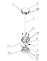
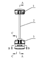
本考案は、センターロック及び当該センターロックが装着されたテントを提供する。図1及び図2に示すように、前記センターロックは、センターロッド2、センターロッド2の一端に固定されたセンタートップキャップ1、及び分離可能にセンターロッド2の他端に接続されたセンターボトムキャップ3を含む。図1に示すように、前記センタートップキャップ1は、ねじ11によってセンターロッド2の一端に固定接続されている。また、前記センターボトムキャップ3とセンターロッド2の他端は、次のような分離可能な接続構造とされる。即ち、図2〜図12に示すように、前記センターボトムキャップ3には、センターロッド2の径方向に往復移動可能な係止部材4が収容されており、当該係止部材4には、センターロッド2を挿通可能な第1通孔41が設けられている。また、前記センターロッド2の端部には、係合溝21及び係合溝21の下端に位置する係合部22が設けられている。センターロックがロック状態の場合には、図6のように、係止部材4における第1通孔41の一部内壁がセンターロッド2の係合溝21に係合し、係合部22の上端面が係止部材4の下端面に当接する。これにより、係合部22が第1通孔41から抜け出ることがなくなり、センターロッド2とセンターボトムキャップ3が互いに接続された状態となる。センターロックが解除状態の場合には、図11のように、係止部材4がセンターロッド2の径方向に移動することで、係止部材4における第1通孔41の内壁が係合溝21から離脱し、係合部22が第1通孔41を通過可能となる。これにより、センターロッド2はセンターボトムキャップ3からも移動可能となり、センターロッド2とセンターボトムキャップ3とが分離される。
The present invention provides a center lock and a tent equipped with the center lock. As shown in FIGS. 1 and 2, the center lock includes a
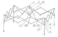
更に、前記センターロックは主にテントに装着されることで、テントに良好な支持効果をもたらす。なお、前記センターロックがその他の装置にも装着可能であることはいうまでもない。図16に示すように、前記センターロックが装着されたテントは、少なくとも3本の支持脚6と、隣接する2本の支持脚6の間に接続される外側伸縮ユニット7、及び各支持脚6に接続される内側伸縮ユニット8を含む。前記外側伸縮ユニット7と内側伸縮ユニット8によりテントの上フレームが構成され、前記上フレームと複数本の支持脚6によりテントのテントフレームが構成される。上フレームはシートで覆われ、テントにおける複数の内側伸縮ユニット8の内端が前記センターロックにより互いに接続されている。本実施例において、前記支持脚6は4本であることから、前記外側伸縮ユニット7と内側伸縮ユニット8はそれぞれ4つとなる。また、操作の利便性から、センターボトムキャップ3を上又は下へ移動させやすいように、前記センタートップキャップ1はセンターロッド2の上端に、センターボトムキャップ3はセンターロッド2の下端に位置している。
Further, the center lock is mainly attached to the tent, thereby providing a good support effect to the tent. Needless to say, the center lock can be mounted on other devices. As shown in FIG. 16, the tent to which the center lock is attached includes at least three
図20に示すようなテントの折り畳み状態では、センターロックのセンタートップキャップ1とセンターボトムキャップ3は互いに分離した状態となる。当該テントを展開する場合には、図19に示すように、まず4本の支持脚6をセンターロックを中心に外側へ展開し、前記外側伸縮ユニット7と内側伸縮ユニット8を徐々に外側へ伸長させる。テントが展開された後に、センターボトムキャップ3をセンターロッド2の方向へ推移、即ちセンターボトムキャップ3を上方へ移動させると、センターロッド2がセンターボトムキャップ3に挿入されて、センターロッド2の係合溝21と第1通孔41の一部内壁が係合する。これにより、係合部22の上端面の一部が係止部材4の下端面の一部に当接して、第1通孔41からの係合部22の抜け落ちが規制される。結果として、センターボトムキャップ3からのセンターロッド2の移動が規制され、センターボトムキャップ3とセンターロッド2との接続が実現される。センターボトムキャップ3とセンターロッド2との接続によりテントの展開状態が固定及び維持されてテント全体がロックされると、外力が加わらない限り、前記内側伸縮ユニット8は自ら伸縮することはない。よって、外側伸縮ユニット7も自ら伸縮することはなく、テントの展開状態の安定性が非常に良好となる。複数の内側伸縮ユニット8はセンターロックの外周に均一に配置されるため、各内側伸縮ユニット8には均一に力が加わる。よって、各支持脚6が均一に上フレームの重力を支えることになり、テント全体の支持効果が高まる。また、当該センターロックが装着されたテントを展開した後に、センターロッドとセンターボトムキャップとを接続すればテントを固定可能なことから、ロックピンでスライダーを固定する従来技術の機械的ロック方式と比較して、本願ではスライダーを支持脚にロックする必要がなくなる。よって、テントの支持脚にスライダー固定用の孔を開設する必要がないため、テント支持脚の強度が強化され、結果としてテント構造の強度が高まって、テントの使用寿命が延びる。当該テントを折り畳む場合には係止部材4を移動させて、係止部材4における第1通孔41の内壁を係合溝21から離脱させる。このとき、係合部22が第1通孔41を通過可能となるため、センターロッド2がセンターボトムキャップ3からも移動可能となり、センターロッド2とセンターボトムキャップ3とが分離される。続いて、センターボトムキャップ3をセンターロッド2から離間する方向へ引くための力を加える。即ち、センターボトムキャップ3を下方へ引くと、内側伸縮ユニット8が図19に示すようにセンターロックへ近接する方向へと収縮する。そして、図20に示すように、最終的には外側伸縮ユニット7が徐々に収縮し、複数本の支持脚6がセンターロックに近接する方向へ収斂される。以上述べたように、本考案に関するセンターロックを備えたテントは、展開又は折り畳み時の操作が非常に容易である。また、テント展開後の支持効果が良好で強度が強いことから、使用寿命が長くなる。且つ、センターロックの構造は簡易で製造しやすく、低コストである。
In the folded state of the tent as shown in FIG. 20, the center
更に、図16〜図18に示すように、各支持脚6にはいずれも支持脚6の長さ方向に移動可能なスライドスリーブ9が覆設されている。支持脚6の上端には固定部10が固定されており、前記外側伸縮ユニット7は互いにヒンジ接続される3つのX型ロッド部材を含む。各X型ロッド部材は、互いにヒンジ接続される第1軒パイプ71と第2軒パイプ72を含み、第1軒パイプ71と第2軒パイプ72のヒンジ接続点が第1軒パイプ71又は第2軒パイプ72の中央点又は中央点近傍に位置する。前記内側伸縮ユニット8は、断面U字形状の接続片で互いにヒンジ接続される第1傾斜屋根パイプ81と第2傾斜屋根パイプ82を含む。前記第1傾斜屋根パイプ81の中央点又は中央点近傍には第1リンク83がヒンジ接続されており、第2傾斜屋根パイプ82の中央点又は中央点近傍には第2リンク84がヒンジ接続されている。4本の第1傾斜屋根パイプの81の内端はいずれもセンターロックのセンタートップキャップ1にヒンジ接続されており、4本の第1リンク83の内端はいずれもセンターロックのセンターボトムキャップ3にヒンジ接続されている。支持脚6上端の固定部10は、X型ロッド部材における2つの第1軒パイプ71の外端と、第2傾斜屋根パイプ82の外端にヒンジ接続されており、支持脚6のスライドスリーブ9が、X型ロッド部材における2つの第2軒パイプ72の外端と、1つの第2リンク84の外端にヒンジ接続されている。本実施例において、第1傾斜屋根パイプ81と第1リンク83、第2傾斜屋根パイプ82と第2リンク84はいずれもY型部材を構成している。即ち、内側伸縮ユニット8は複数のY型部材から構成される。他の実施例において、前記内側伸縮ユニット8は、図21に示すように複数のX型部材から構成されてもよい。このとき、内側伸縮ユニット8の各X型部材は、互いにヒンジ接続される第3傾斜屋根パイプ85と第4傾斜屋根パイプ86を含む。内側伸縮ユニット8の最も内側に位置するX型部材のうち、第3傾斜屋根パイプ85の内端はセンターロックのセンタートップキャップ1にヒンジ接続され、第4傾斜屋根パイプ86の内端はセンターロックのセンターボトムキャップ3にヒンジ接続される。内側伸縮ユニット8の最も外側に位置するX型部材のうち、第3傾斜屋根パイプ85の外端はスライドスリーブ9にヒンジ接続され、第4傾斜屋根パイプ86の外端は固定部10にヒンジ接続される。
Further, as shown in FIGS. 16 to 18, each
テントの上フレームが上記構造を採用した上で、テントを展開すべくセンターロックのセンターボトムキャップ3を上方へ推移させる過程では、センターボトムキャップ3の上方移動によって内側伸縮ユニット8が外側に伸長する。また、スライドスリーブ9が支持脚6の長さ方向に沿って上方へ移動することで、外側伸縮ユニット7と4本の支持脚6が、テント全体が完全に展開してセンターボトムキャップ3とセンターロッド2の下端が接続されるまで徐々に伸長する。逆に、センターボトムキャップ3とセンターロッド2の下端を分離した後に、センターボトムキャップ3を下方に引く過程では、センターボトムキャップ3の下方への移動によって内側伸縮ユニット8が内側へ収縮する。また、スライドスリーブ9が支持脚6の長さ方向に沿って下方へ移動することで、外側伸縮ユニット7と4本の支持脚6が、テント全体が完全に折り畳まれるまで徐々に収斂していく。
In the process of moving the center
更に、図1、図6及び図11に示すように、前記センターボトムキャップ3は、複数のねじで互いに固定接続されたボトムキャップ台31とボトムキャップ蓋32を含む。前記センターボトムキャップ3におけるボトムキャップ台31とボトムキャップ蓋32の接続箇所には収容空間311が開設されており、センターボトムキャップ3の外壁には収容空間311と連通する開口312が開設されている。前記係止部材4は、前記収容空間311と開口312に貫設され、ボトムキャップ台31とボトムキャップ蓋32との間に位置してボトムキャップ蓋32に支持されている。前記収容空間311は全体がボトムキャップ台31に設けられてもよいし、全体がボトムキャップ蓋32に設けられてもよく、また、ボトムキャップ台31とボトムキャップ蓋32双方に設けられてもよい。前記ボトムキャップ台31とボトムキャップ蓋32は取り外し可能にねじで接続されるため、センターボトムキャップ3と係止部材4の取り付けに便利である。また、センターボトムキャップ3のボトムキャップ台31とセンタートップキャップ1にはいずれも八つの接続片318が設けられており、八つの接続片318によって、90°間隔で設けられた4組の接続片群が構成されている。即ち、各接続片群が前記接続片318を2つずつ含み、これら2つの接続片318間に収容溝が形成されている。4本の第1傾斜屋根パイプ81の内端がそれぞれセンタートップキャップ1における4つの収容溝内に配置されるとともに、ボルトによって接続片318にヒンジ接続されている。当該ボルト端部のねじにはナットが接続されている。4本の第1リンク83の内端はそれぞれボトムキャップ31における4つの収容溝内に配置されるとともに、ボルトによって接続片318にヒンジ接続されている。当該ボルト端部のねじにはナットが接続されている。
Further, as shown in FIGS. 1, 6 and 11, the center
本願において、前記係止部材4には2つの実施例がある。係止部材4の実施例1を図1〜図15に、係止部材4の実施例2を図21〜図26に示す。具体的には、係止部材4の実施例1において、係止部材4は一体化部材、即ち一体構造とされる。このとき、図6及び図11に示すように、前記収容空間311にはセンターロッド2の径方向に圧縮可能な弾性部材が設けられ、当該弾性部材の両端は、係止部材4と収容空間311の内壁にそれぞれ当接している。前記ボトムキャップ台31には脱落防止部313が突設されており、前記係止部材4には脱落防止部313を収容する凹溝42が開設されている。センターロックがロック状態の場合、弾性部材自身の弾性力によって係止部材4をセンターロッド2の径方向に付勢することで、第1通孔41の一部内壁を係合溝21内に位置させる。即ち、第1通孔41の一部内壁と係合溝21を係合させて、センターロッド2がその軸方向において第1通孔41から離脱することを規制する。また、前記脱落防止部313の一部側面と凹溝42の一部内壁を当接させることで、収容空間311からの係止部材4の離脱が規制される。好ましくは、図1、図13及び図14に示すように、前記弾性部材をバネ5とし、前記係止部材4の前記開口312から遠い側の一端に突出するガイド支持部43を設ける。当該ガイド支持部43の横断面は十字形であり、係止部材4が内側へ移動する過程で良好な安定性を持ち、且つセンターロックのロック状態において構造全体が良好な安定性を備えるよう、前記バネ5がガイド支持部43に覆設される。
In the present application, the locking
好ましくは、図13に示すように、前記第1通孔41は並列配置された係合孔部411と通孔部412を含む。前記係合孔部411の直径は係合溝21の直径未満とはしない。即ち、係合孔部411の直径は係合溝21の直径と同じかやや大きい。また、前記通孔部412の直径は係合部22の直径より大きい。従って、センターロックのロック状態においては、図4に示すように、センターロッド2下端の係合溝21は第1通孔41の係合孔部411と係合し、センターロッド2と第1通孔41の通孔部412は偏心して配置される。即ち、センターロッド2の軸線は通孔部412の軸線と平行ではあるが重なりはしない。センターロックのロック解除が必要な場合、ユーザは係止部材押圧部44に力を加えて押動し、図9に示すように、センターロッド2と係止部材4における第1通孔41の通孔部412とが同心に配置されるまで、弾性部材を圧縮するように係止部材押圧部44を内側に移動させる。即ち、センターロッド2の軸線と通孔部412の軸線を重ねると、係合孔部411の内壁が係合溝21から移動して、センターロッド2下端の係合部22が通孔部412から移動可能となる。
Preferably, as shown in FIG. 13, the first through
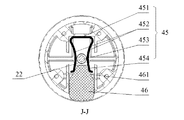
係止部材4の実施例2において、係止部材4は分離構造とされ、図22〜図26に示すように、弾性ワイヤ45とロック解除押動片46を含む。前記弾性ワイヤ45はU字形状であり、弾性ワイヤ本体部451と弾性ワイヤ本体部451の両端にそれぞれ設けられる2つの弾性変形部452を含む。2つの弾性変形部452はX形状とされるため、2つの弾性変形部452の中央には前記第1通孔41を形成するためのスリット453が設けられる。当該スリット453は弾性変形部452の間隔が最も小さな開口部分であり、弾性変形部452の端部が挿入口454を形成している。前記ロック解除押動片46の内端は挿入口454内に位置する。自然な状態では、前記スリット453の口径は係合溝21の直径よりも小さいか等しい。センターロッド2をセンターボトムキャップ3に挿入する際、係合部22は、センターロッド2の係合溝21が弾性ワイヤ45のスリット453の内壁に嵌まるまでスリット453を押し広げる。すると、図23及び図24に示すように、スリット453が弾性ワイヤ45自身の弾性復元力によって収斂し、スリット453の内壁がセンターロッド2の係合溝21内に係合されることで、センターボトムキャップ3とセンタートップキャップ1の位置がロックされる。ロック解除が必要な場合には、スリット453の口径が係合部22の直径より大きくなるまで、ロック解除押動片46を内側に押し込んで弾性ワイヤ45の挿入口454を押し広げる。これにより、図25及び図26に示すように、係合部22はスリット453を通過可能となり、センタートップキャップ1とセンターボトムキャップ3との分離が実現されて、テントの収縮動作が達成される。
In the second embodiment of the locking
好ましくは、図23及び図25に示すように、前記ボトムキャップ台31に脱落防止部313を突設し、前記ロック解除押動片46に脱落防止部313を収容する凹溝42を開設する。脱落防止部313が凹溝42に掛合することで、収容空間311からのロック解除押動片46の離脱が防止されるとともに、ロック解除時のロック解除押動片46による過度な押圧を防止可能となる。前記ロック解除押動片46には弾性変形部452の端部と接触する2つのガイド面461が設けられており、当該ガイド面461は、弾性ワイヤ45から遠い側の一端に向かって拡大するように傾斜している。即ち、ロック解除押動片46の内端は、ロック解除押動片46を内側へ押動する際に弾性ワイヤ45の挿入口454とスリット453を正確に押し広げられるよう、台形状とされている。
Preferably, as shown in FIGS. 23 and 25, a drop-
好ましくは、係止部材4を移動させやすいよう、係止部材4の少なくとも一部をセンターボトムキャップ3の外部に配置して、係止部材押圧部44を形成する。
Preferably, the locking
更に、図6に示すように、前記ボトムキャップ台31にはセンターロッド2の挿通を許容する第2通孔314が設けられている。第2通孔314の軸線はセンターロッド2の軸線と重なる。また、前記ボトムキャップ蓋32には前記係合部22を収容するとともに、係合部22の外壁に適合した収容孔321が設けられている。前記第2通孔314、第1通孔41及び収容孔321は互いに連通する。センターロックのロック状態では、前記センターロッド2の下端がボトムキャップ台31の第2通孔314と係止部材4の第1通孔41に順に貫設され、前記係合部22がボトムキャップ蓋32の収容孔321に収容される。収容孔321の内壁形状が係合部22の外壁形状と適合していることから、収容孔321の内壁は係合部22の外壁に密着する。よって、センターロッド2の係合部22が外力によって揺動やずれ等を生じることが防止されるため、センターロックにおける良好なロック信頼性が高まる。
Further, as shown in FIG. 6, the
以上述べたように、ボトムキャップ台31、ボトムキャップ蓋32、バネ5、係止部材4、センターロッド2及びセンタートップキャップ1等からなるセンターロックは、ロックの際、ユーザがセンターボトムキャップ3を上方へ移動させるよう押動し、センターボトムキャップ3とセンタートップキャップ1との距離を徐々に狭める。係止部材4に外力が加わっていない場合、係止部材4はバネ5の弾性力のみを受け、且つバネ5の弾性力によって、係止部材4における凹溝42の一部内壁とボトムキャップ台31における脱落防止部313の一部外壁とが当接する。よって、係止部材4はバネ5の弾性力を受けても前記収容空間311内に収容されたままとなり、収容空間311から外部に離脱することがない。また、係止部材4における第1通孔41の通孔部412とボトムキャップ台31の第2通孔314は偏心して配置される。ユーザは、センターロッド2の下端がボトムキャップ台31の第2通孔314内に進入するまでセンターボトムキャップ3を上方に移動させ続ける。ユーザがセンターボトムキャップ3を上方へ移動させるよう力を加え続け、センターロッド2の下端における係合部22が係止部材4の第1通孔41の上端に進入すると、ユーザは係止部材4に対するバネ5の付勢力に抗して係止部材4を内側に移動させるよう力を加える。これにより、センターロッド2下端の係合部22は係止部材4の第1通孔41を通過して、ボトムキャップ蓋32の収容孔321に収容される。また、係止部材4はバネ5の弾性力によって元の位置に戻り、第1通孔41の係合孔部411とセンターロッド2の係合溝21とが係合する。この結果、センターロッド2とセンターボトムキャップ3との接続が完了し、センターロックのロックが実現される。ロック解除の際、ユーザはバネ5の弾性力に抗して係止部材4を内側に移動させるよう、係合部材押圧部44を内側に押圧する。そして、係合孔部411の内壁が係合溝21から離脱してセンターロッド2と第1通孔41の通孔部412が整列した後、センターボトムキャップ3を下側に移動させるよう引っ張ればよい。
As described above, the center lock made up of the
更に、センターロッド2をボトムキャップ台31及び係止部材4に挿入しやすいよう、図6及び図11に示すように、センターロッド2がセンターボトムキャップ3に挿入される方向に沿って、前記第2通孔314は、直径が徐々に縮小する第1テーパー部315、円柱部316及び直径が徐々に拡大する第2テーパー部317を順に含む。前記円柱部316の直径はセンターロッド2の直径よりもやや大きい。従って、ボトムキャップ台31を上方へ移動させてセンターロッド2の下端に接続する際、第2通孔314上端の第1テーパー部315の開口が大きいことから、係合部22をボトムキャップ台31に挿入しやすい。図15に示すように、前記第1通孔41の上端には面取り処理を施し、直径が徐々に縮小する面取り部413を形成している。よって、第1通孔41上端の開口もまた大きく、且つ傾斜を有することから、係止部材4への係合部22の挿入を容易とするガイド作用が奏される。センターロッド2とセンターボトムキャップ3を分離する場合にはボトムキャップ台31を下方へ移動させるが、第2通孔314下端の第2テーパー部317は開口が大きいことから、係合部22を第2通孔314から離脱させやすい。好ましくは、前記係合溝21を環状溝とし、前記係合部22の端部にガイド部221を設ける。当該ガイド部221は、係止部材4の第1通孔41に入りやすく且つ摩耗しにくいよう、半球状又は直径が徐々に縮小するテーパー状とされる。
Further, in order to facilitate the insertion of the
更に、図1に示すように、センターロック構造の強度を保証しつつ、原材料を節約してコストを削減するために、前記ボトムキャップ蓋32には複数の材料節減溝322が開設される。また、前記センターボトムキャップ3の側面は、センターボトムキャップ3を掴みやすいように円弧形状とされる。
Further, as shown in FIG. 1, a plurality of
以上述べたように、本考案は従来技術における種々の欠点を効果的に解決しており、高い産業上の利用価値を有する。 As described above, the present invention effectively solves various drawbacks in the prior art and has high industrial utility value.
1 センタートップキャップ
2 センターロッド
3 センターボトムキャップ
4 係止部材
5 バネ
6 支持脚
7 外側伸縮ユニット
8 内側伸縮ユニット
9 スライドスリーブ
10 固定部
11 ねじ
21 係合溝
22 係合部
31 ボトムキャップ台
32 ボトムキャップ蓋
41 第1通孔
42 凹溝
43 ガイド支持部
44 係止部材押圧部
45 弾性ワイヤ
46 ロック解除押動片
71 第1軒パイプ
72 第2軒パイプ
81 第1傾斜屋根パイプ
82 第2傾斜屋根パイプ
83 第1リンク
84 第2リンク
85 第3傾斜屋根パイプ
86 第4傾斜屋根パイプ
221 ガイド部
311 収容空間
312 開口
313 脱落防止部
314 第2通孔
315 第1テーパー部
316 円柱部
317 第2テーパー部
318 接続片
321 収容孔
322 材料節減溝
411 係合孔部
412 通孔部
413 面取り部
451 弾性ワイヤ本体部
452 弾性変形部
453 スリット
454 挿入口
461 ガイド面
DESCRIPTION OF
Claims (14)
前記センターボトムキャップ(3)には、センターロッド(2)の径方向に往復移動可能な係止部材(4)が収容され、当該係止部材(4)には、センターロッド(2)を挿通可能な第1通孔(41)が設けられ、前記センターロッド(2)の端部には、係合溝(21)及び係合溝(21)の下端に位置する係合部(22)が設けられ、
センターロックのロック状態において、係止部材(4)における第1通孔(41)の一部内壁がセンターロッド(2)の係合溝(21)に係合し、係合部(22)の上端面が係止部材(4)の下端面に当接し、
センターロックのロック解除状態において、係止部材(4)における第1通孔(41)の内壁が係合溝(21)から離脱し、係合部(22)が第1通孔(41)を通過可能となる、ことを特徴とするセンターロック。 A center lock including a center rod (2), a center top cap (1) fixed to one end of the center rod (2), and a center bottom cap (3) detachably connected to the other end of the center rod (2) In
The center bottom cap (3) accommodates a locking member (4) capable of reciprocating in the radial direction of the center rod (2), and the center rod (2) is inserted into the locking member (4). A possible first through hole (41) is provided, and an engagement groove (21) and an engagement portion (22) positioned at the lower end of the engagement groove (21) are provided at the end of the center rod (2). Provided,
In the locked state of the center lock, a partial inner wall of the first through hole (41) in the locking member (4) is engaged with the engagement groove (21) of the center rod (2), and the engagement portion (22) The upper end surface contacts the lower end surface of the locking member (4),
In the unlocked state of the center lock, the inner wall of the first through hole (41) in the locking member (4) is disengaged from the engaging groove (21), and the engaging portion (22) passes through the first through hole (41). Center lock characterized by being able to pass through.
センターロックのロック状態において、前記弾性部材は第1通孔(41)の一部内壁と係合溝(21)を係合させ、前記脱落防止部(313)と凹溝(42)の内壁とを当接させる、ことを特徴とする請求項2に記載のセンターロック。 The locking member (4) has an integral structure, and the accommodation space (311) is provided with an elastic member that is compressible in the radial direction of the center rod (2). 4) and the inner wall of the accommodating space (311), respectively, the bottom cap base (31) is provided with a drop-off prevention part (313), and the locking member (4) is provided with a drop-off prevention part (313). A ditch (42) to accommodate
In the locked state of the center lock, the elastic member engages a part of the inner wall of the first through hole (41) with the engagement groove (21), and the drop prevention part (313) and the inner wall of the concave groove (42) The center lock according to claim 2, wherein the center lock is brought into contact.
センターロックのロック解除状態において、前記ロック解除押動片(46)は弾性ワイヤ(45)の挿入口(454)とスリット(453)を押し広げるために用いられる、ことを特徴とする請求項2に記載のセンターロック。 The locking member (4) has a separation structure and includes an elastic wire (45) and an unlocking push piece (46). The elastic wire (45) is U-shaped and has an elastic wire main body (451). ) And two elastic deformation portions (452) provided at both ends of the elastic wire main body portion (451), respectively, and the first through hole (41) is formed between the two elastic deformation portions (452). Slit (453) is provided, the end of the elastically deformable portion (452) forms an insertion port (454), and the inner end of the unlocking push piece (46) is located in the insertion port (454). And
The unlocking pressing piece (46) is used to push the insertion opening (454) and the slit (453) of the elastic wire (45) in the unlocked state of the center lock. Center lock as described in
センターロックのロック状態において、前記脱落防止部(313)と凹溝(42)の内壁が当接する、ことを特徴とする請求項5に記載のセンターロック。 The bottom cap base (31) is provided with a drop-off prevention part (313), and the unlocking push piece (46) is provided with a concave groove (42) for accommodating the drop-off prevention part (313).
6. The center lock according to claim 5, wherein in the locked state of the center lock, the drop-off preventing portion (313) and the inner wall of the concave groove (42) abut.
更に、請求項1〜11のいずれか1項に記載のセンターロックを含み、複数の内側伸縮ユニット(8)の内端が前記センターロックによって互いに接続される、ことを特徴とするテント。 At least three support legs (6), an outer telescopic unit (7) connected between two adjacent support legs (6), and an inner telescopic unit (8) connected to each support leg (6) In a tent in which an upper frame is constituted by the outer telescopic unit (7) and the inner telescopic unit (8),
The tent further comprising the center lock according to any one of claims 1 to 11, wherein inner ends of a plurality of inner telescopic units (8) are connected to each other by the center lock.
前記内側伸縮ユニット(8)が、互いにヒンジ接続される第1傾斜屋根パイプ(81)と第2傾斜屋根パイプ(82)を含み、前記第1傾斜屋根パイプ(81)に第1リンク(83)がヒンジ接続され、第2傾斜屋根パイプ(82)に第2リンク(84)がヒンジ接続され、前記第1傾斜屋根パイプ(81)の内端とセンターロックのセンタートップキャップ(1)とがヒンジ接続され、第1リンク(83)の内端とセンターロックのセンターボトムキャップ(3)とがヒンジ接続され、第1軒パイプ(71)の外端と第2傾斜屋根パイプ(82)の外端とが固定部(10)にヒンジ接続され、第2軒パイプ(72)の外端と第2リンク(84)の外端とが何れもスライドスリーブ(9)にヒンジ接続される、ことを特徴とする請求項12に記載のテント。 Each support leg (6) is covered with a slide sleeve (9) movable in the length direction of the support leg (6), and a fixing portion (10) is fixed to the upper end of the support leg (6). The telescopic unit (7) includes a plurality of X-shaped rod members that are hinged to each other, and each X-shaped rod member includes a first eaves pipe (71) and a second eaves pipe (72) that are hinged to each other,
The inner telescopic unit (8) includes a first inclined roof pipe (81) and a second inclined roof pipe (82) hinged to each other, and the first inclined roof pipe (81) has a first link (83). Is hinged, the second inclined roof pipe (82) is hinged to the second link (84), and the inner end of the first inclined roof pipe (81) and the center top cap (1) of the center lock are hinged. Connected, the inner end of the first link (83) and the center bottom cap (3) of the center lock are hinged, and the outer end of the first eaves pipe (71) and the outer end of the second inclined roof pipe (82) Are hinge-connected to the fixing part (10), and the outer end of the second eaves pipe (72) and the outer end of the second link (84) are both hinge-connected to the slide sleeve (9). And in claim 12 Mounting of the tent.
前記内側伸縮ユニット(8)が、互いにヒンジ接続される複数のX型部材を含み、各X型部材が、互いにヒンジ接続される第3傾斜屋根パイプ(85)と第4傾斜屋根パイプ(86)を含み、前記第3傾斜屋根パイプ(85)の内端とセンターロックのセンタートップキャップ(1)とがヒンジ接続され、第4傾斜屋根パイプ(86)の内端とセンターロックのセンターボトムキャップ(3)とがヒンジ接続され、第1軒パイプ(71)の外端と第4傾斜屋根パイプ(86)の外端とが何れも固定部(10)にヒンジ接続され、第2軒パイプ(72)の外端と第3傾斜屋根パイプ(85)の外端とが何れもスライドスリーブ(9)にヒンジ接続される、ことを特徴とする請求項12に記載のテント。 Each support leg (6) is covered with a slide sleeve (9) movable in the length direction of the support leg (6), and a fixing portion (10) is fixed to the upper end of the support leg (6). The telescopic unit (7) includes a plurality of X-shaped rod members that are hinged to each other, and each X-shaped rod member includes a first eaves pipe (71) and a second eaves pipe (72) that are hinged to each other,
The inner telescopic unit (8) includes a plurality of X-shaped members hinged to each other, and each X-shaped member is hinge-connected to the third inclined roof pipe (85) and the fourth inclined roof pipe (86). The inner end of the third inclined roof pipe (85) and the center top cap (1) of the center lock are hinge-connected, and the inner end of the fourth inclined roof pipe (86) and the center bottom cap of the center lock ( 3) is hinge-connected, and the outer end of the first eaves pipe (71) and the outer end of the fourth inclined roof pipe (86) are both hinge-connected to the fixed portion (10), and the second eaves pipe (72 13) and the third inclined roof pipe (85) are both hingedly connected to the slide sleeve (9).
Priority Applications (8)
| Application Number | Priority Date | Filing Date | Title |
|---|---|---|---|
| JP2015004155U JP3200660U (en) | 2015-08-18 | 2015-08-18 | Center lock and tent |
| PCT/CN2016/091675 WO2017028659A1 (en) | 2015-08-18 | 2016-07-26 | Central lock and tent |
| DE202016008850.6U DE202016008850U1 (en) | 2015-08-18 | 2016-07-26 | pavilion |
| GB1804045.1A GB2557150B (en) | 2015-08-18 | 2016-07-26 | Central lock and tent |
| CN201680023809.3A CN108026736B (en) | 2015-08-18 | 2016-07-26 | Central lock and tent |
| US15/549,164 US10273710B2 (en) | 2015-08-18 | 2016-07-26 | Central lock and canopy |
| DE112016003736.8T DE112016003736B4 (en) | 2015-08-18 | 2016-07-26 | Central locking and tent |
| CN202010119087.XA CN111287548B (en) | 2015-08-18 | 2016-07-26 | Central lock and tent |
Applications Claiming Priority (1)
| Application Number | Priority Date | Filing Date | Title |
|---|---|---|---|
| JP2015004155U JP3200660U (en) | 2015-08-18 | 2015-08-18 | Center lock and tent |
Related Child Applications (1)
| Application Number | Title | Priority Date | Filing Date |
|---|---|---|---|
| JP2017123793A Continuation JP6438076B2 (en) | 2017-06-26 | 2017-06-26 | Center lock and tent |
Publications (1)
| Publication Number | Publication Date |
|---|---|
| JP3200660U true JP3200660U (en) | 2015-10-29 |
Family
ID=54478410
Family Applications (1)
| Application Number | Title | Priority Date | Filing Date |
|---|---|---|---|
| JP2015004155U Ceased JP3200660U (en) | 2015-08-18 | 2015-08-18 | Center lock and tent |
Country Status (6)
| Country | Link |
|---|---|
| US (1) | US10273710B2 (en) |
| JP (1) | JP3200660U (en) |
| CN (2) | CN111287548B (en) |
| DE (2) | DE112016003736B4 (en) |
| GB (1) | GB2557150B (en) |
| WO (1) | WO2017028659A1 (en) |
Cited By (1)
| Publication number | Priority date | Publication date | Assignee | Title |
|---|---|---|---|---|
| US10060153B2 (en) | 2016-10-17 | 2018-08-28 | Ningbo Dongrun Mining Co., Ltd. | Tent supporting structure |
Families Citing this family (28)
| Publication number | Priority date | Publication date | Assignee | Title |
|---|---|---|---|---|
| US9995056B2 (en) * | 2014-07-01 | 2018-06-12 | Shengyong Yang | Collapsible gazebo frame with single activation feature |
| US11299906B2 (en) * | 2016-07-26 | 2022-04-12 | Shengyong Yang | Collapsible canopy with a central lock and reinforcement bars |
| USD925687S1 (en) * | 2016-07-26 | 2021-07-20 | Shengyong Yang | Canopy center top cap, pole and pull-down pad combination |
| US10669738B2 (en) * | 2016-07-26 | 2020-06-02 | Shengyong Yang | Collapsible canopy frame having a central lock |
| US10107005B2 (en) * | 2016-10-17 | 2018-10-23 | Ningbo Dongrun Mining Co., Ltd. | Tent supporting structure |
| US9956981B1 (en) * | 2016-10-31 | 2018-05-01 | Radio Flyer Inc. | Canopy pole system |
| US20190234102A1 (en) * | 2018-01-30 | 2019-08-01 | Linhai Zhenyi Arts and Crafts Co., Ltd. | Folding Canopy |
| CN207794778U (en) * | 2018-01-30 | 2018-08-31 | 临海市臻一工艺品有限公司 | A kind of portable folding paulin |
| CN108518120A (en) * | 2018-05-29 | 2018-09-11 | 浙江健盛休闲用品有限公司 | A kind of break camp rotation unlocking type center locking device |
| US11306511B2 (en) * | 2018-05-29 | 2022-04-19 | Zhejiang Jiansheng Leisure Products Co., Ltd | Rotary unlocking central lock device for foldable tent |
| CN208669085U (en) * | 2018-06-21 | 2019-03-29 | 客贝利(厦门)休闲用品有限公司 | A kind of awning |
| CN109914904B (en) * | 2019-03-22 | 2023-10-03 | 绍兴雅格伞业有限公司 | Push type tent supporting component and tent |
| US11821228B2 (en) * | 2019-04-26 | 2023-11-21 | Zhejiang Jiansheng Leisure Products Co., Ltd | Foldable tent center lock device with rotary unlocking structure |
| CN210508639U (en) * | 2019-04-26 | 2020-05-12 | 浙江健盛休闲用品有限公司 | Novel central locking device for folding tent |
| US11199023B2 (en) | 2019-04-26 | 2021-12-14 | Zhejiang Jiansheng Leisure Products Co., Ltd | Central locking apparatus for folding tent |
| US10822829B1 (en) * | 2019-06-26 | 2020-11-03 | Linhai Zhenyi Arts & Crafts Co., Ltd. | Folding canopy with central locking mechanism |
| CN211286916U (en) * | 2019-08-06 | 2020-08-18 | 浙江健盛休闲用品有限公司 | Central lock for folding tent |
| US10941585B2 (en) | 2019-08-06 | 2021-03-09 | Zhejiang Jiansheng Leisure Products Co., Ltd | Central lock for folding tent |
| US11559146B2 (en) * | 2019-08-07 | 2023-01-24 | Wonderland Switzerland Ag | Foldable playard having X-frame assemblies and canopy cover |
| TWI753519B (en) | 2019-08-07 | 2022-01-21 | 瑞士商明門瑞士股份有限公司 | Foldable playard |
| CN211572859U (en) * | 2019-12-10 | 2020-09-25 | 浙江易泰进出口有限公司 | Pull-down type release pull rod locking device for folding tent |
| CN212295870U (en) * | 2019-12-25 | 2021-01-05 | 浙江健盛休闲用品有限公司 | Central bidirectional rotary locking mechanism for folding tent |
| CN111938434B (en) * | 2020-07-24 | 2022-01-28 | 六安索伊电器制造有限公司 | Brewing device of coffee machine |
| CN111894345A (en) * | 2020-08-28 | 2020-11-06 | 南京可康户外用品有限责任公司 | Sunshade support and sunshade |
| CN112031515B (en) * | 2020-09-11 | 2022-02-01 | 开封大学 | Outdoor tent for travel |
| US20230064601A1 (en) * | 2021-08-30 | 2023-03-02 | Global Maxlead Ltd. | Rotating locking structure |
| WO2024045239A1 (en) * | 2022-08-31 | 2024-03-07 | 武义申华工贸股份有限公司 | Central locking structure of pop-up tent |
| USD983642S1 (en) * | 2022-12-02 | 2023-04-18 | Maxlead Innovations Co., Ltd | Locking bar for canopy |
Family Cites Families (34)
| Publication number | Priority date | Publication date | Assignee | Title |
|---|---|---|---|---|
| US233255A (en) * | 1880-10-12 | William kimble | ||
| US2530765A (en) * | 1948-03-05 | 1950-11-21 | Sanford Saari H | Tent |
| US4945936A (en) * | 1989-08-16 | 1990-08-07 | Surrendi Dennis C | Collapsible tent and frame therefor |
| JP3020664U (en) * | 1995-02-06 | 1996-02-06 | 株式会社神菱 | Door locking device |
| IT1279125B1 (en) * | 1995-04-18 | 1997-12-04 | Bruzolo Manifatt Gestind Mb | BUSH IN THE BACKREST OF THE VEHICLE SEAT FOR ADJUSTING THE HEADREST. |
| US5632290A (en) * | 1996-08-16 | 1997-05-27 | Ling Kuo; Cheng M. | Automatically collapsible umbrellas |
| US6199572B1 (en) | 1998-07-24 | 2001-03-13 | Negocios De Estela S.A. | Collapsible shelter/tent with frame locking mechanism |
| US6176246B1 (en) * | 1999-03-31 | 2001-01-23 | Fu Tai Umbrella Works, Ltd. | Multiple-fold automatic umbrella with simplified structure and shortened length |
| US6684893B2 (en) * | 2001-10-01 | 2004-02-03 | Shih-Shin Kuo | Simplified controlling apparatus of an automatic umbrella |
| US6729341B2 (en) * | 2002-04-02 | 2004-05-04 | Youth Lee | Control apparatus for an automatic-opened umbrella |
| US6929017B2 (en) * | 2002-10-29 | 2005-08-16 | Taewoong Byun | Collapsible canopy framework structure of a regular polygon |
| US20040084074A1 (en) * | 2002-11-06 | 2004-05-06 | Steve Chiu | Canopy support |
| US6796154B2 (en) * | 2002-11-13 | 2004-09-28 | Chad Gebow | Trailer wheel lock |
| US7240686B2 (en) | 2003-11-12 | 2007-07-10 | Caravan Canopy International, Inc. | Collapsible canopy having reduced length |
| CN2861392Y (en) * | 2005-12-09 | 2007-01-24 | 厦门革新塑胶制品有限公司 | Top fixing device of folded tent |
| CN101452316B (en) * | 2007-12-04 | 2011-08-10 | 康准电子科技(昆山)有限公司 | Fastening device |
| CN201169955Y (en) * | 2008-01-22 | 2008-12-24 | 李成熙 | Connecting pieces of automatic foldable tent rack |
| US8469045B2 (en) * | 2009-06-23 | 2013-06-25 | Nanqing ZHOU | Collapsible tent frame |
| CN201620635U (en) * | 2010-03-09 | 2010-11-03 | 蔡葵 | Plug-in-type self-locking bracket for mosquito net and tent |
| CN201835613U (en) * | 2010-08-11 | 2011-05-18 | 黄山市亿利工贸有限公司 | Antitheft lock for disposable container |
| US8578956B2 (en) * | 2011-01-27 | 2013-11-12 | Jeffrey D. Dankenbring | Roof support assembly for collapsible shelter |
| CN202125133U (en) * | 2011-05-18 | 2012-01-25 | 中山市鼎瑞塑胶实业有限公司 | Antitheft cap for meter box |
| KR101253113B1 (en) * | 2012-11-22 | 2013-04-10 | 이동학 | Baungalow of easy install and dismantling |
| CN203050229U (en) * | 2012-12-25 | 2013-07-10 | 浙江泰普森休闲用品有限公司 | Tent framework and tent |
| CN103362358B (en) * | 2013-07-22 | 2015-04-22 | 温州市通用锁具有限公司 | Firm and simple U-shaped bracket |
| CN203846854U (en) * | 2014-04-22 | 2014-09-24 | 鹤山市通达户外用品有限公司 | Novel weatherproof tent support |
| CN204024196U (en) * | 2014-05-13 | 2014-12-17 | 蔚孜电子商务(上海)有限公司 | A kind of tent with single-point lock |
| US9995058B2 (en) * | 2015-06-01 | 2018-06-12 | Xiamen Innovation Metal Products Co., Ltd. | Automatically foldable tent frames and mechanisms for automatically folding and unfolding tent frames |
| US10597897B2 (en) * | 2016-07-26 | 2020-03-24 | Shengyong Yang | Collapsible canopy with a self locking central lock |
| US10669738B2 (en) * | 2016-07-26 | 2020-06-02 | Shengyong Yang | Collapsible canopy frame having a central lock |
| US10107005B2 (en) * | 2016-10-17 | 2018-10-23 | Ningbo Dongrun Mining Co., Ltd. | Tent supporting structure |
| US10273711B2 (en) * | 2016-10-17 | 2019-04-30 | Ningbo Dongrun Mining Co., Ltd. | Spring assist system for a canopy frame |
| US9956981B1 (en) * | 2016-10-31 | 2018-05-01 | Radio Flyer Inc. | Canopy pole system |
| JP6438076B2 (en) * | 2017-06-26 | 2018-12-12 | 蔚孜電子商務(上海)有限公司 | Center lock and tent |
-
2015
- 2015-08-18 JP JP2015004155U patent/JP3200660U/en not_active Ceased
-
2016
- 2016-07-26 CN CN202010119087.XA patent/CN111287548B/en active Active
- 2016-07-26 GB GB1804045.1A patent/GB2557150B/en active Active
- 2016-07-26 US US15/549,164 patent/US10273710B2/en active Active
- 2016-07-26 DE DE112016003736.8T patent/DE112016003736B4/en active Active
- 2016-07-26 DE DE202016008850.6U patent/DE202016008850U1/en active Active
- 2016-07-26 CN CN201680023809.3A patent/CN108026736B/en active Active
- 2016-07-26 WO PCT/CN2016/091675 patent/WO2017028659A1/en active Application Filing
Cited By (1)
| Publication number | Priority date | Publication date | Assignee | Title |
|---|---|---|---|---|
| US10060153B2 (en) | 2016-10-17 | 2018-08-28 | Ningbo Dongrun Mining Co., Ltd. | Tent supporting structure |
Also Published As
| Publication number | Publication date |
|---|---|
| CN111287548A (en) | 2020-06-16 |
| CN108026736B (en) | 2020-04-07 |
| WO2017028659A1 (en) | 2017-02-23 |
| DE112016003736T5 (en) | 2018-05-03 |
| CN111287548B (en) | 2021-08-06 |
| GB201804045D0 (en) | 2018-04-25 |
| GB2557150A (en) | 2018-06-13 |
| GB2557150B (en) | 2021-01-13 |
| CN108026736A (en) | 2018-05-11 |
| US20180238075A1 (en) | 2018-08-23 |
| DE202016008850U1 (en) | 2020-02-17 |
| US10273710B2 (en) | 2019-04-30 |
| DE112016003736B4 (en) | 2021-07-08 |
Similar Documents
| Publication | Publication Date | Title |
|---|---|---|
| JP3200660U (en) | Center lock and tent | |
| JP6438076B2 (en) | Center lock and tent | |
| US10669738B2 (en) | Collapsible canopy frame having a central lock | |
| KR100558356B1 (en) | The tent and frame for automatic umbrella style canopy tent | |
| WO2014082424A1 (en) | Tent top opening and closing mechanism | |
| JP3123506U (en) | Semi-circular folding tent support frame apex fixing device | |
| US8485208B2 (en) | Canopy tent | |
| US8496019B2 (en) | Tent | |
| CN201731245U (en) | Portable tripod capable of being expanded or contracted quickly | |
| US8448656B2 (en) | Roof connecting mechanism of foldable tent | |
| US10337204B2 (en) | Tent top folding and unfolding structure | |
| JP3238921U (en) | Double-acting locking tent frame structure | |
| CN206581688U (en) | A kind of sunshade collapsible top | |
| KR200483476Y1 (en) | Top frame of folding tent | |
| KR20060133162A (en) | The tent and frame for automatic umbrella style canopy tent | |
| KR200344232Y1 (en) | Frame for Automatic Umbrella Style Canopy Tent | |
| KR100587832B1 (en) | One touch tent | |
| KR100735013B1 (en) | The Tent and Frame for Automatic Umbrella Style Canopy Tent | |
| JP2017169359A (en) | Frame structure for housing body of indirect hot-line tool | |
| KR20060122187A (en) | Canopy | |
| KR200294997Y1 (en) | Device for locking poles for canopy tent with umbrella-type collapsible frame | |
| KR200359030Y1 (en) | Frame for tent | |
| KR20100010615U (en) | Foldable Tent | |
| KR20150012764A (en) | prop coupler for parasol | |
| CN115227009A (en) | Middle rod folding structure of multi-folding umbrella |
Legal Events
| Date | Code | Title | Description |
|---|---|---|---|
| R150 | Certificate of patent or registration of utility model |
Ref document number: 3200660 Country of ref document: JP Free format text: JAPANESE INTERMEDIATE CODE: R150 |
|
| A624 | Registrability report (other person) |
Free format text: JAPANESE INTERMEDIATE CODE: A624 Effective date: 20170524 |
|
| S801 | Written request for registration of abandonment of right |
Free format text: JAPANESE INTERMEDIATE CODE: R321801 |
|
| ABAN | Cancellation due to abandonment | ||
| R350 | Written notification of registration of transfer |
Free format text: JAPANESE INTERMEDIATE CODE: R350 |