JP3194582U - Golf practice jig - Google Patents
Golf practice jig Download PDFInfo
- Publication number
- JP3194582U JP3194582U JP2014004995U JP2014004995U JP3194582U JP 3194582 U JP3194582 U JP 3194582U JP 2014004995 U JP2014004995 U JP 2014004995U JP 2014004995 U JP2014004995 U JP 2014004995U JP 3194582 U JP3194582 U JP 3194582U
- Authority
- JP
- Japan
- Prior art keywords
- plate
- golf practice
- face surface
- ball
- practice jig
- Prior art date
- Legal status (The legal status is an assumption and is not a legal conclusion. Google has not performed a legal analysis and makes no representation as to the accuracy of the status listed.)
- Expired - Lifetime
Links
- 235000009508 confectionery Nutrition 0.000 claims abstract description 19
- 239000000463 material Substances 0.000 claims abstract description 9
- 239000004698 Polyethylene Substances 0.000 description 2
- 239000004743 Polypropylene Substances 0.000 description 2
- 229920000122 acrylonitrile butadiene styrene Polymers 0.000 description 2
- 239000000853 adhesive Substances 0.000 description 2
- 230000001070 adhesive effect Effects 0.000 description 2
- 229920001903 high density polyethylene Polymers 0.000 description 2
- 239000004700 high-density polyethylene Substances 0.000 description 2
- 229920001684 low density polyethylene Polymers 0.000 description 2
- 239000004702 low-density polyethylene Substances 0.000 description 2
- 229920001179 medium density polyethylene Polymers 0.000 description 2
- 239000004701 medium-density polyethylene Substances 0.000 description 2
- 238000000034 method Methods 0.000 description 2
- -1 polyethylene Polymers 0.000 description 2
- 229920000573 polyethylene Polymers 0.000 description 2
- 229920001155 polypropylene Polymers 0.000 description 2
- 229920002635 polyurethane Polymers 0.000 description 2
- 239000004814 polyurethane Substances 0.000 description 2
- 239000011118 polyvinyl acetate Substances 0.000 description 2
- 229920002689 polyvinyl acetate Polymers 0.000 description 2
- 239000011347 resin Substances 0.000 description 2
- 229920005989 resin Polymers 0.000 description 2
- 239000004925 Acrylic resin Substances 0.000 description 1
- 229920000178 Acrylic resin Polymers 0.000 description 1
- 241000282326 Felis catus Species 0.000 description 1
- 239000004793 Polystyrene Substances 0.000 description 1
- 229920001328 Polyvinylidene chloride Polymers 0.000 description 1
- XECAHXYUAAWDEL-UHFFFAOYSA-N acrylonitrile butadiene styrene Chemical compound C=CC=C.C=CC#N.C=CC1=CC=CC=C1 XECAHXYUAAWDEL-UHFFFAOYSA-N 0.000 description 1
- 239000004676 acrylonitrile butadiene styrene Substances 0.000 description 1
- 230000007423 decrease Effects 0.000 description 1
- 229920001971 elastomer Polymers 0.000 description 1
- 239000006260 foam Substances 0.000 description 1
- 229920003023 plastic Polymers 0.000 description 1
- 239000004033 plastic Substances 0.000 description 1
- 229920003229 poly(methyl methacrylate) Polymers 0.000 description 1
- 239000004926 polymethyl methacrylate Substances 0.000 description 1
- 239000004800 polyvinyl chloride Substances 0.000 description 1
- 239000005033 polyvinylidene chloride Substances 0.000 description 1
- 229920002379 silicone rubber Polymers 0.000 description 1
Images
Landscapes
- Dry Development In Electrophotography (AREA)
- Cleaning In Electrography (AREA)
Abstract
【課題】正しいスイングを可能とするゴルフ練習治具を提供する。【解決手段】ゴルフ練習治具100は、フェース面に装着されると共に当該フェース面とは異なる材質からなる板状体からなり、この板状体はフェース面のスイートスポットを避けて平面的に形成する。板状体は、一定の幅を有する半円環形状又は逆U字形状であって端部1aが円環の径方向に突出し、この端部1a及び突出部4に凸部5又は凹部を設ける。板状体は、弾性体からなる。フェース面に対して略垂直方向となりスイートスポットを囲めるように板状体にゴルフボールの半径以下の高さの壁板2を設ける。更に、壁板2の上端上面の中央にマーク6を設ける。【選択図】図1A golf practice jig that enables a correct swing is provided. A golf practice jig 100 is composed of a plate-like body which is mounted on a face surface and made of a material different from the face surface, and the plate-like body is formed in a plane while avoiding a sweet spot on the face surface. To do. The plate-like body has a semi-annular shape or an inverted U shape having a certain width, and an end portion 1a protrudes in the radial direction of the annular shape, and a convex portion 5 or a concave portion is provided on the end portion 1a and the protruding portion 4. . The plate-like body is made of an elastic body. A wall plate 2 having a height equal to or less than the radius of the golf ball is provided on the plate-like body so as to be substantially perpendicular to the face surface and surround the sweet spot. Further, a mark 6 is provided in the center of the upper surface of the upper end of the wall plate 2. [Selection] Figure 1
Description
本考案は、正しいスイングを可能とするゴルフ練習治具に関するものである。 The present invention relates to a golf practice jig that enables a correct swing.
従来から特許文献1に開示されているようなゴルフ練習用器具が知られている。このゴルフ練習用器具は、ゴルフクラブのフェース面のスイートスポットに対し、これを囲むような線状に突起した凸状部材を設けたものである。この凸状部材は、ゴムやプラスチック等の弾力性を備えたものにより構成される。
Conventionally, a golf practice device as disclosed in
ゴルファーが構えた状態でヘッドを見ると、凸状部材がクラブのフェース面から突出して見えるので、スイートスポットを認識できる。また、凸状部材にボールが当たってしまった場合には、打球方向がばらつくのでゴルファーにスイートスポットを意識してボールを打つように働きかけることができる。 When the head is viewed with the golfer holding it, the convex member appears to protrude from the face surface of the club, so that the sweet spot can be recognized. In addition, when the ball hits the convex member, the hitting direction varies, so that the golfer can be conscious of hitting the sweet spot and hit the ball.
しかしながら、上記従来のゴルフ練習器具では、スイートスポットを大幅に外すと凸状部材に当たることなくボールが飛んでしまうので、ボールをパッティングした場合にスイートスポットに当たっているか否か判別し難いという問題点があった。本考案は、係る問題点を解決するためになされたものである。 However, in the above conventional golf practice equipment, if the sweet spot is greatly removed, the ball will fly without hitting the convex member, so it is difficult to determine whether or not it hits the sweet spot when putting the ball. It was. The present invention has been made to solve such problems.
本考案のゴルフ練習治具は、フェース面に装着されると共に当該フェース面とは異なる材質からなる板状体からなり、この板状体は前記フェース面のスイートスポットを避けて平面的に形成したことを特徴とする。 The golf practice jig of the present invention is composed of a plate-like body made of a material different from the face surface, which is mounted on the face surface, and the plate-like body is formed in a plane to avoid the sweet spot on the face surface. It is characterized by that.
また、前記板状体は、一定の幅を有する半円環形状又は逆U字形状であって端部が円環の径方向に突出し、この端部及び突出部に凸部又は凹部を設けた構成とするのが好ましい。 Further, the plate-like body has a semi-annular shape or an inverted U shape having a certain width, and an end portion projects in the radial direction of the annular shape, and a convex portion or a concave portion is provided on the end portion and the projecting portion. A configuration is preferable.
更に、前記板状体は、弾性体とするのが好ましく、前記フェース面に対して略垂直方向となり前記スイートスポットを囲めるように前記板状体にゴルフボールの半径以下の高さの壁板を設けても良い。更に、前記壁の上端上面の中央にマークを設けても良い。 Further, the plate-like body is preferably an elastic body, and a wall plate having a height equal to or less than the radius of the golf ball is provided on the plate-like body so as to be substantially perpendicular to the face surface and surround the sweet spot. It may be provided. Furthermore, a mark may be provided at the center of the upper surface of the upper end of the wall.
(実施の形態1)
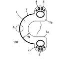
図1は、本考案の実施の形態1に係るゴルフ練習治具を示す斜視図である。図2は、図1に示したゴルフ練習治具の平面図、図3は上面図、図4は側面図である。また、図5は、図2の一部拡大図である。このゴルフ練習治具100は、ゴルフのパターのフェース面に装着するものであり、逆U字形状の平面板状体からなる本体1と、前記フェース面に対して略垂直方向となるように本体1の円弧部分の外側端縁から立設した壁板2とから構成される。本体1の裏面(フェース面に取り付ける側の面)には接着剤が塗布され、図示しない離型シートで保護されている。
(Embodiment 1)
FIG. 1 is a perspective view showing a golf practice jig according to
本体1は、パターとは異なる材質の成形品である。例えば、薄肉にすることで一定の弾性力を備え得るポリエチレン (PE)、高密度ポリエチレン(HDPE)、中密度ポリエチレン(MDPE)、低密度ポリエチレン(LDPE)、ポリプロピレン (PP)、ポリ塩化ビニル (PVC)、ポリ塩化ビニリデン、ポリスチレン (PS)、ポリ酢酸ビニル (PVAc)、ポリウレタン(PUR)、ABS樹脂(アクリロニトリルブタジエンスチレン樹脂)、AS樹脂、アクリル樹脂 (PMMA)等を用いることができる。また、シリコンゴム等の弾性体を用いることができる。この本体1の開口部3は、フェース面のスイートスポットを避け得るような形状及び大きさに設定されており、全体で厚さは均一になっている。本体1は板状体であるから本質的に一定の幅Wを備え、その幅Wも略一定である。当該幅Wは、具体的には8mm以上15mm以下とし、開口部3の径を20mm以上30mm以下するのが好ましい。この程度の幅Wがスイング時にぶれるものと想定され、それ以上ずれるとフェース面の端近傍に当たるので違和感があり使用者が認識できるからである。また、幅Wを15mm以上20mm以下とし、開口部3の径を10mm以上20mm以下としても良い。この寸法設定は、プレイヤーの習熟度により適宜設定できる。後者の例ではレベルが高いプレイヤー用となる。
The
本体1は、端部が外側ないし円環の径方向に突出部4を備えており、当該突出部4及び逆U字形状の端部1aには、複数の凸部5が施されている。この凸部5はデザイン的な性質も有するものであるが、この凸部5にボールが当たることでボールの進行方向に大きな変化が与えられる。特に、ボールに対して凸部5が複数同時に接触しないような密度や配置とするのが好ましい。例えば、細かい凸部5を複数グリッド状に設けるとボールが比較的直進する傾向にあるので、凸部5同士がランダムに離れた距離にあったり、高さが異なったり、形状が異なったりするのが好ましい。特に、凸部5は先端が球状であると、ボールに当たったときに当該ボールの進行方向が乱れやすいので好ましい。なお、同図の例では、猫の足跡形状である。なお、当該凸部5は必須ではなく、突出部4にはデザイン的な絵柄のみを施すようにしても良い。
The
更に、前記壁板2は、前記スイートスポットを囲めるように設けられる。この壁板2は、本体1と一体成形され同じ素材で形成されたものである。また、高さは一定であり、平均的なゴルフボールの半径以下とするのが好ましい。半径以下とすることでボールが隠れて中心を見難いためである。具体的には、壁板の高さは5mm〜20mmとする。厚さは1mm前後で良い。更に、壁板2の上端上面の中央にはマーク6が設けられる。マーク6は、凹凸形状により一体成形しても良いし、シールを付加して設けても良い。マーク6は、フェース面に垂直方向となるように直線で形成される。なお、壁板2は、本体1と別の素材で成形して取り付けるようにしても良い。
Further, the
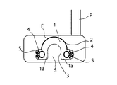
次に、このゴルフ練習治具の使用方法を説明する。まず、図6に示すように、パターPのフェース面Fに本考案のゴルフ練習治具100を装着する。このとき、本体1の裏面の離型シートを剥して接着剤が塗布された面を露出する。そして、フェース面FのスイートスポットSが開口部3により露出するように、換言すればフェース面Fの周囲に本体1が位置するように貼り付ける。ここで、本体1がパターとは別の素材、例えば弾性体により成形されているので、フェース面Fが多少湾曲していても本体1が僅かに変形して綺麗に貼り付けることができる。
Next, how to use this golf practice jig will be described. First, as shown in FIG. 6, the
この状態で、図7に示すように、壁板2がフェース面Fから略垂直方向に突出するかたちになる。また、本体1を取り付ける際、壁板2のマーク6が適切な位置(最上位置)になるようにしておく。これにより、スイートスポットSの周囲に本体1が取り付けられたことになる。
In this state, as shown in FIG. 7, the
使用者はボールBを地面に置き、パターPを正しく構え、フェース面FをボールBに対して当てるように動作し(図7の矢印方向)、位置を確認する。このとき、ボールBが壁板2の内部に入るようなイメージでヘッド及びフェース面Fを調節する。これにより、ボールBに対するフェース面Fの角度等をより正確に判断できる。また、壁板2のマーク6がボールBの中心にくるように目視しながら調整をする。
The user places the ball B on the ground, holds the putter P correctly, operates to touch the face surface F against the ball B (in the direction of the arrow in FIG. 7), and confirms the position. At this time, the head and the face surface F are adjusted in such an image that the ball B enters the inside of the
そして、いったんボールBからヘッドを離し、再び軽くスイングしてフェース面FでボールBをパッティングする。このとき、ボールBが開口部3の内側、即ちスイートスポットSに当たると、スイングした方向にボールBが飛ぶ。一方、ヘッドがずれてしまうと、前記ボールBに本体1が当たってしまい、特に本体1の角部(開口部3の周縁)に当たると、ボールBはスイングした方向とは全く違う方向に飛ぶ。また、突出部4にかけて凸部5が形成されていることから、凸部5にボールBが当たると、思わぬ方向にボールBが飛んでしまうので、使用者はパッティングに問題があることを理解できる。
Then, once the head is released from the ball B, the ball B is put on the face surface F by swinging lightly again. At this time, when the ball B hits the inside of the
また、凸部5でない部分にボールBが当たっても、本体1の厚さにより開口部3の角がボールBに当たることで当該ボールBが思わぬ方向に飛ぶことになるし、本体1はヘッドとは異なる材料、具体的には弾性体により成形されているので、打った感覚に違和感を得、パッティングに問題があったことを理解できる。
Further, even if the ball B hits a portion other than the
以上、本考案のゴルフ練習治具100によれば、本体1が一定の幅Wを有していることから、スイートスポットSを外してパッティングするとボールBの挙動が大きく変わるのでスイートスポットSから外れていることを確実に認識可能である。また、壁板2によりボールBに対するフェース面Fの角度や位置を正確に矯正できる。更に、上記ではパットの練習を例に挙げたが、ドライバーに装着してフォームの矯正をするようにしても良い。
As described above, according to the
(実施の形態2)
図8は、本考案の実施の形態2に係るゴルフ練習治具を示す斜視図である。このゴルフ練習治具200は、上記実施の形態1に係るゴルフ練習治具100の壁板2を省略した構造であり、且つ、本体1の形状をC字形状ないし円弧形状としたものである。その他の構成は上記実施の形態1と同じである。また、本体1の厚さは、スイートスポット側(内側)ほど厚く、外側に向けて緩やかに薄くなっている。即ち、本体1の厚さが場所によって異なるようにする。これにより、本体1にボールBが当たると、パッティング方向とは異なる方向に飛ぶことになる。
(Embodiment 2)
FIG. 8 is a perspective view showing a golf practice jig according to
また、壁板2の代わりに、複数の棒状突起51が設けられている。この棒状突起51は、フェース面FのスイートスポットSを囲むようにして位置するようにする。使用者は、ボールBが棒状突起51により形成したエリアの内部に入るようなイメージでヘッド及びフェース面Fを調節する。これにより、ボールBに対するフェース面Fの角度等をより正確に判断できる。
Further, instead of the
100 ゴルフ練習治具
1 本体
2 壁板
3 開口部
4 突出部
5 凸部
DESCRIPTION OF
Claims (5)
Furthermore, the golf practice jig | tool as described in any one of Claims 1-4 which provided the mark in the center of the upper end upper surface of the said wall.
Priority Applications (1)
| Application Number | Priority Date | Filing Date | Title |
|---|---|---|---|
| JP2014004995U JP3194582U (en) | 2014-09-18 | 2014-09-18 | Golf practice jig |
Applications Claiming Priority (1)
| Application Number | Priority Date | Filing Date | Title |
|---|---|---|---|
| JP2014004995U JP3194582U (en) | 2014-09-18 | 2014-09-18 | Golf practice jig |
Publications (2)
| Publication Number | Publication Date |
|---|---|
| JP3194582U true JP3194582U (en) | 2014-11-27 |
| JP3194582U7 JP3194582U7 (en) | 2017-09-21 |
Family
ID=52145458
Family Applications (1)
| Application Number | Title | Priority Date | Filing Date |
|---|---|---|---|
| JP2014004995U Expired - Lifetime JP3194582U (en) | 2014-09-18 | 2014-09-18 | Golf practice jig |
Country Status (1)
| Country | Link |
|---|---|
| JP (1) | JP3194582U (en) |
Cited By (1)
| Publication number | Priority date | Publication date | Assignee | Title |
|---|---|---|---|---|
| JP2016059638A (en) * | 2014-09-18 | 2016-04-25 | 哲 勝又 | Golf training jig |
-
2014
- 2014-09-18 JP JP2014004995U patent/JP3194582U/en not_active Expired - Lifetime
Cited By (1)
| Publication number | Priority date | Publication date | Assignee | Title |
|---|---|---|---|---|
| JP2016059638A (en) * | 2014-09-18 | 2016-04-25 | 哲 勝又 | Golf training jig |
Similar Documents
| Publication | Publication Date | Title |
|---|---|---|
| US9327176B1 (en) | Golf putting training kit | |
| US8870672B2 (en) | Portable golf putting target | |
| JP3194582U (en) | Golf practice jig | |
| JP6419684B2 (en) | Golf tee | |
| JP2016059638A (en) | Golf training jig | |
| US9352204B2 (en) | Practice hitting tee | |
| US20180169493A1 (en) | Practice hitting tee | |
| JP3175571U (en) | Training bat | |
| US20180193710A1 (en) | Golf accessory holding unit | |
| TW201542274A (en) | Golf tee | |
| US9770638B2 (en) | Swing training device | |
| JP2022526691A (en) | Golf tee for slicing prevention | |
| US20180043230A1 (en) | Versatile batting tee adapter | |
| KR102218681B1 (en) | Golf mat | |
| JP2008302208A (en) | Golf tee setting device | |
| JP2012120743A (en) | Golf tee | |
| JP2015043068A (en) | Recorder and ring-shaped member used for the same | |
| JP2005305058A (en) | Scattering preventive tool of golf tee | |
| JP6175353B2 (en) | Practice putter mat | |
| KR20200110927A (en) | Holder of golf ball and golf tee | |
| US9526962B2 (en) | Ball tossing game formation kit | |
| JP2015213555A (en) | Golf tee | |
| KR102170419B1 (en) | Putting play hall cup | |
| KR200463928Y1 (en) | Direction indicator for golf tee | |
| JP2012016369A (en) | Golf practice equipment |
Legal Events
| Date | Code | Title | Description |
|---|---|---|---|
| R150 | Certificate of patent or registration of utility model |
Ref document number: 3194582 Country of ref document: JP Free format text: JAPANESE INTERMEDIATE CODE: R150 |
|
| A623 | Registrability report |
Free format text: JAPANESE INTERMEDIATE CODE: A623 Effective date: 20170629 |
|
| R231 | Written correction (descriptions, etc.) |
Free format text: JAPANESE INTERMEDIATE CODE: R231 |
|
| R157 | Certificate of patent or utility model (correction) |
Free format text: JAPANESE INTERMEDIATE CODE: R157 |
|
| A521 | Request for written amendment filed |
Free format text: JAPANESE INTERMEDIATE CODE: A523 Effective date: 20170731 |
|
| R250 | Receipt of annual fees |
Free format text: JAPANESE INTERMEDIATE CODE: R250 |
|
| R250 | Receipt of annual fees |
Free format text: JAPANESE INTERMEDIATE CODE: R250 |
|
| R250 | Receipt of annual fees |
Free format text: JAPANESE INTERMEDIATE CODE: R250 |
|
| R250 | Receipt of annual fees |
Free format text: JAPANESE INTERMEDIATE CODE: R250 |
|
| R250 | Receipt of annual fees |
Free format text: JAPANESE INTERMEDIATE CODE: R250 |
|
| R250 | Receipt of annual fees |
Free format text: JAPANESE INTERMEDIATE CODE: R250 |
|
| R250 | Receipt of annual fees |
Free format text: JAPANESE INTERMEDIATE CODE: R250 |
|
| EXPY | Cancellation because of completion of term |


