JP3194033U - Massage equipment - Google Patents
Massage equipment Download PDFInfo
- Publication number
- JP3194033U JP3194033U JP2014004442U JP2014004442U JP3194033U JP 3194033 U JP3194033 U JP 3194033U JP 2014004442 U JP2014004442 U JP 2014004442U JP 2014004442 U JP2014004442 U JP 2014004442U JP 3194033 U JP3194033 U JP 3194033U
- Authority
- JP
- Japan
- Prior art keywords
- fixed shaft
- skin
- shaft portion
- selection switch
- massage
- Prior art date
- Legal status (The legal status is an assumption and is not a legal conclusion. Google has not performed a legal analysis and makes no representation as to the accuracy of the status listed.)
- Expired - Fee Related
Links
Images


Classifications
-
- A—HUMAN NECESSITIES
- A61—MEDICAL OR VETERINARY SCIENCE; HYGIENE
- A61H—PHYSICAL THERAPY APPARATUS, e.g. DEVICES FOR LOCATING OR STIMULATING REFLEX POINTS IN THE BODY; ARTIFICIAL RESPIRATION; MASSAGE; BATHING DEVICES FOR SPECIAL THERAPEUTIC OR HYGIENIC PURPOSES OR SPECIFIC PARTS OF THE BODY
- A61H15/00—Massage by means of rollers, balls, e.g. inflatable, chains, or roller chains
- A61H15/02—Massage by means of rollers, balls, e.g. inflatable, chains, or roller chains adapted for simultaneous treatment with light, heat or drugs
Abstract
【課題】顔部又は頭部の皮膚近傍の血行をより促進することができるマッサージ具を提供する。【解決手段】このマッサージ具1は、電気機械部材22、23、24を収容するとともに、選択スイッチ21が露設された長尺の把持部2と、把持部2に固定されてその一端から延出し、選択スイッチ21の操作に応じて熱せられる固定軸部3と、固定軸部3の先端部の周りに回動可能状態で配置され、固定軸部3の熱を受けて顔部又は頭部の皮膚に接触させる表面まで伝達する炭素成形体41を有する皮膚接触部4と、を備えてなる。【選択図】図1A massage device that can further promote blood circulation in the vicinity of the skin of the face or head. The massage device 1 accommodates electromechanical members 22, 23, 24, a long grip portion 2 with a selection switch 21 exposed, and is fixed to the grip portion 2 and extends from one end thereof. The fixed shaft portion 3 is heated in response to the operation of the selection switch 21 and is arranged in a rotatable state around the distal end portion of the fixed shaft portion 3. And a skin contact portion 4 having a carbon molded body 41 that transmits to the surface to be brought into contact with the skin. [Selection] Figure 1
Description
本考案は、顔部又は頭部のマッサージのためのマッサージ具に関する。 The present invention relates to a massage tool for facial or head massage.
近年、顔部については美容のため、頭部については髪の育成促進のために、それらをマッサージ具を用いてマッサージし皮膚近傍の血行を良くすることが広く行われている。顔部のマッサージのためのマッサージ具の中には、長尺状の把手部の先端にローラーを回動自在に設け、それを顔部に押し当てて往復させることによってマッサージするものがある(例えば、特許文献1及び2)。また、頭部のマッサージのためのマッサージ具の中には、長尺状の把手部の先端に多数の弾性突起を持つヘッド部に設け、弾性突起の先端を頭皮に押し当てることによってマッサージするものがある(例えば、特許文献3)。
In recent years, it has been widely practiced to improve the blood circulation in the vicinity of the skin by massaging them with a massage tool for the beauty of the face and the promotion of hair growth for the head. Some massage devices for massage of the face part are provided with a roller at the tip of the long handle part so as to be able to rotate and press the face part against the face part to make a massage (for example,
しかしながら、特許文献1〜3を含めた従来のマッサージ具は、そのマッサージ効果の面で、具体的には顔部又は頭部の皮膚近傍の血行をより促進するという面で、改善の余地があると思われる。
However, the conventional massage tools including
本考案は、係る事由に鑑みてなされたものであり、その目的は、顔部又は頭部の皮膚近傍の血行をより促進することができるマッサージ具を提供することにある。 This invention is made | formed in view of the reason which concerns, The objective is to provide the massage tool which can accelerate | stimulate the blood circulation of the skin vicinity of a face part or a head more.
上記目的を達成するために、請求項1に記載のマッサージ具は、電気機械部材を収容するとともに、選択スイッチが露設された長尺の把持部と、該把持部に固定されてその一端から延出し、前記選択スイッチの操作に応じて熱せられる固定軸部と、該固定軸部の先端部の周りに回動可能状態で配置され、固定軸部の熱を受けて顔部又は頭部の皮膚に接触させる表面まで伝達する炭素成形体を有する皮膚接触部と、を備えてなることを特徴とする。 In order to achieve the above object, a massage device according to claim 1 accommodates an electromechanical member, and has a long grip portion with an exposed selection switch, and is fixed to the grip portion from one end thereof. A fixed shaft portion that is extended and heated in response to the operation of the selection switch, and is arranged in a rotatable state around the distal end portion of the fixed shaft portion. A skin contact portion having a carbon molded body that transmits to a surface to be brought into contact with the skin.
請求項2に記載のマッサージ具は、請求項1に記載のマッサージ具において、前記皮膚接触部は、前記炭素成形体の表面に、ダイヤモンドライクカーボンの被膜が設けられていることを特徴とする。
The massage tool according to
請求項3に記載のマッサージ具は、請求項1又は2に記載のマッサージ具において、前記固定軸部は、前記選択スイッチの操作により振動することを特徴とする。
The massage tool according to
本考案のマッサージ具によれば、皮膚接触部の温度を高めて顔部又は頭部の皮膚に押し当て、炭素成形体からの熱伝導と遠赤外線放射により、皮膚近傍の温度を効率的に高めながらマッサージすることができ、その結果、皮膚近傍の血行をより促進することができる。 According to the massage device of the present invention, the temperature of the skin contact portion is raised and pressed against the skin of the face or head, and the temperature in the vicinity of the skin is efficiently increased by heat conduction and far infrared radiation from the carbon molded body. Can be massaged, and as a result, blood circulation near the skin can be further promoted.
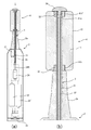
以下、本考案を実施するための好ましい形態を説明する。本考案の実施形態に係るマッサージ具1は、顔部又は頭部のマッサージのためのマッサージ具であって、図1(a)及び(b)、図2(a)及び(b)に示すように、長尺の把持部2と、把持部2に固定され、その一端から延出する固定軸部3と、固定軸部3の先端部の周りに回動可能状態で配置される皮膚接触部4と、を備えている。図1(a)においては、把持部2の内部の構成について、電気機械部材とその電気配線(破線部分)を模式的に示している。
Hereinafter, preferred embodiments for carrying out the present invention will be described. A
把持部2は、長尺、すなわち大略長筒状の箱体であり、底部に外部からの操作が可能なように選択スイッチ21を露設し(露出させて設け)ている。また、把持部2は、内部に、電気機械部材である電池22、22’、サーモスタット23、モータ24などを収容している。電池22、22’は、選択スイッチ21の操作により、固定軸部3を熱するために後述の発熱体32に通電してそれを発熱させたり、固定軸部3を振動させるためにモータ24に通電して回転運動をさせたりする。モータ24の回転運動は振動を生じさせ、その振動は振動伝達手段24Aを介して固定軸部3に伝達される。なお、把持部2には、固定軸部3の中間部までその周りを囲む突出部2aが形成されている。
The
図1(a)に示すこの実施形態は、選択スイッチ21によりオンとオフの2個の状態を選択できるものとし、オンの状態で固定軸部3を熱し、かつ、振動させるようにしたものである。より詳細には、電池22の正極とサーモスタット23の一端子の間、サーモスタット23の他端子と発熱体32の一端子の間、発熱体32の他端子と電池22’の負極の間、にそれぞれ電気配線が設けられ、また、電池22の正極とモータ24の一端子の間、モータ24の他端子と電池22’の負極の間、にそれぞれ電気配線が設けられ、電池22’の正極と選択スイッチ21の一端子の間、選択スイッチ21の他端子と電池22の負極の間、にそれぞれ電気配線が設けられている。オフ状態(図において選択スイッチ21が右にスライドした状態)にあると、2個の電池22、22’間は電気的に接続されず、オン状態(図において選択スイッチ21が左にスライドした状態)では、2個の電池22、22’間が電気的に接続され、発熱体32とモータ24はともに通電状態となり、固定軸部3は熱せられ、かつ、振動する。
In this embodiment shown in FIG. 1A, it is assumed that two states, ON and OFF, can be selected by the
選択スイッチ21や電気機械部材、及びその電気配線は、仕様に合わせて、適宜変更することが可能である。例えば、選択スイッチ21を2個設け、それぞれのオンの状態で固定軸部3を熱したり振動させたりすることも可能である。また、電池22、22’の部分は、1個又は3個以上の一次電池や充電池に変更することが可能であり、また、装着状態で充電可能なようにすることも可能である。
The selection switch 21, the electromechanical member, and the electrical wiring thereof can be appropriately changed according to the specifications. For example, it is possible to provide two
サーモスタット23は、皮膚接触部4の表面、すなわち皮膚に接触する部分が適温(例えば、最高温度40〜45℃程度)になるように制御するためのものであり、温度検出部分が後述の固定軸本体31に接触して配設されている。サーモスタット23は温度検出部分が検出する温度に従って、発熱体32の通電を制御する。
The
固定軸部3は、熱伝導性が高い筒状の固定軸本体31(例えば、アルミニウム製やステンレス鋼製など)、その内部に通電により熱を発生する発熱体32、固定軸本体31と後述の炭素成形体41の間に設けられるベアリング33、33’と、固定軸本体31の先端に着脱自在に取り付けられ留め部材34を有している。発熱体32は、例えば、絶縁体で被覆したニクロム線を固定軸本体31の基端近傍から先端近傍まで往復させて配設したものを用いることができる。固定軸本体31は、発熱体32によって熱せられ、熱を皮膚接触部4に伝えるとともに、前述のサーモスタット23により温度が検出される。ベアリング33、33’は、内側面が固定軸本体31、外側面が炭素成形体41に接触するように炭素成形体41の両端部に設けられている。なお、ベアリング33、33’の構造は既知のベアリングと同様であるので説明は省略する。留め部材34は、皮膚接触部4が固定軸本体31の先端側から外れないように留め、また、先端側のベアリング33’を保護する。
The
皮膚接触部4は、使用者がマッサージ具1を皮膚に押し当てて往復運動をさせると、それに追従して回動するものである。皮膚接触部4は、固定軸部3の熱を受けて皮膚に接触させる表面まで伝達する炭素成形体41から主に成る。
When the user presses the
この炭素成形体41は、焼成により高密度で整った炭素の結晶構造が等方(方向によらず)に形成されており、全体が一体的に形成されるもので、以下のように製造することができる。すなわち、黒鉛、又は炭化物(竹炭など)の炭素粉にバインダを5重量%程度加えて固め、水圧などで等方に加圧して所定の塊(例えば方形もの)に成形する。そして、酸素が欠乏した状態で加熱し、2500〜3500℃程度で長時間かけて焼成する。この状態で、原料の炭素粉同士は結合し炭素が結晶化(黒鉛化、定形炭素化)する。なお、バインダは昇温途中の1000〜1200℃程度で揮発させる。その後、加熱を止め、温度を下げ、所望の形状に加工する。このようにして出来あがった炭素成形体41は、バインダが揮発しているので、ほぼ100%(99%以上)が炭素材となっている。また、かさ密度(かさ比重)は、1.77Mg/m3以上である。
The carbon molded
炭素成形体41は、一体の結晶構造であるために、物理的強度が高く、また熱伝導率も高い(100〜140W/(m・K)程度)。また、放射する遠赤外線の量が多く(図3参照)、温度が高いほど多い。なお、図3は、炭素成形体41の製造方法と同様にして製造した25×25×2(mm)の炭素成形体の遠赤外線放射特性である。実線が炭素成形体、破線が黒体の放射輝度である。分析装置は日本電子製フーリエ変換赤外分光光度計JIR−5500型/赤外放射ユニットIR―IRR200を用い、測定温度は50℃とした。
Since the carbon molded
炭素成形体41は、図1(b)に示すように、略円柱状であって、固定軸部3が挿入される挿入孔41aが中心軸の位置に貫通して形成されている。また、挿入孔41aの両方の開口部近傍には、前述のベアリング33、33’が嵌め込まれる凹部41b、41b’が形成されている。炭素成形体41は、例えば、外径が15〜30mm程度、軸方向の長さが30〜50mm程度とすることができる。挿入孔41aの内径は、固定軸部3の外径よりも若干大きくして(例えば、0.1mm程度)、固定軸部3から炭素成形体41への熱伝導を極力妨げないようにする。
As shown in FIG. 1B, the carbon molded
炭素成形体41は、皮膚への接触が容易となるように種々の形状を採用することが可能である。例えば、図4に示すような複数の環状の溝41cを形成することも可能である。
The carbon molded
皮膚接触部4の炭素成形体41は、その表面にダイヤモンドライクカーボン(DLC)の被膜42(例えば、厚みが2〜4μm程度)が設けられている。このダイヤモンドライクカーボンの被膜42は、プラズマCVDやPVDなどにより、気相成長させて結晶構造の炭素が形成されるものであり、炭素成形体41との密着性が良く、しかも、硬質である。また、殺菌性を得るために、ダイヤモンドライクカーボンの気相成長時にフッ素及び/又は銀を混合することも可能である。
The carbon molded
このマッサージ具1の使用方法は以下のとおりである。すなわち、使用者は、把持部2を手で持って選択スイッチ21を操作し、固定軸部3を熱しかつ振動させ、皮膚接触部4を皮膚に押し当てて適当な力で往復運動をさせることによって皮膚をマッサージする。
The usage method of this
この往復運動に追従して、皮膚接触部4は回動する。皮膚接触部4は、炭素成形体41の物理的強度が高く被膜42が硬質であるので、摩耗や破損が起こり難い。また、炭素成形体41や被膜42は、人体を形成する有機物の構成物質と同じであるため、皮膚に接触したときそれに馴染むものであり、人体への安全性が高い。それらは、金属やプラスチックでないので、金属アレルギーや化学物質アレルギーが生じないのは勿論である。
Following this reciprocating motion, the
選択スイッチ21の操作により固定軸部3が熱せられると、固定軸部3の熱は皮膚接触部4の炭素成形体41に伝導し、その温度は高くなる。炭素成形体41は、皮膚に、熱伝導により直に熱を伝えるとともに、温度が高くなるに従って量が多くなった遠赤外線を放射する。この遠赤外線は、皮膚近傍の深部を加温する。これら伝導熱と遠赤外線の輻射熱により皮膚近傍の温度は効率的に高められるので、皮膚接触部4による圧力との相乗効果により、皮膚近傍の血行をより促進することができるのである。
When the fixed
また、炭素成形体41は、熱伝導率が高いので、固定軸部3が挿入される挿入孔41aから表面までの温度の降下が少ない。そのため、発熱体32の温度を余り高くせずに済むとともに、固定軸本体31に接触しているサーモスタット23による温度制御の精度も良くなる。
Further, since the carbon molded
また、選択スイッチ21の操作により固定軸部3が振動すると、振動は皮膚接触部4を介して皮膚近傍に伝えられる。この振動によって、皮膚近傍の血行を更に促進することができる。
Further, when the fixed
以上、本考案の実施形態に係るマッサージ具1について説明したが、本考案は、上述の実施形態に記載したものに限られることなく、実用新案登録請求の範囲に記載した事項の範囲内でのさまざまな設計変更が可能である。例えば、マッサージ具1に振動の機能を設けないことも場合によっては可能である。この場合、上記のモータ24などは不要になる。
As mentioned above, although the
1 マッサージ具
2 把持部
21 選択スイッチ
22、23、24 電気機械部材
3 固定軸部
4 皮膚接触部
41 炭素成形体
41a 挿入孔
42 被膜
DESCRIPTION OF
Claims (3)
該把持部に固定されてその一端から延出し、前記選択スイッチの操作に応じて熱せられる固定軸部と、
該固定軸部の先端部の周りに回動可能状態で配置され、固定軸部の熱を受けて顔部又は頭部の皮膚に接触させる表面まで伝達する炭素成形体を有する皮膚接触部と、を備えてなることを特徴とするマッサージ具。 A long holding part that accommodates the electromechanical member and the selection switch is exposed, and
A fixed shaft portion that is fixed to the grip portion and extends from one end thereof, and is heated in accordance with the operation of the selection switch;
A skin contact portion that is disposed in a rotatable state around the distal end portion of the fixed shaft portion, and has a carbon molded body that receives heat from the fixed shaft portion and transmits the surface to the surface of the face portion or the head to be brought into contact with the skin; A massage device characterized by comprising.
前記皮膚接触部は、前記炭素成形体の表面に、ダイヤモンドライクカーボンの被膜が設けられていることを特徴とするマッサージ具。 The massage device according to claim 1,
The said skin contact part is provided with the diamond-like carbon film on the surface of the said carbon molded object, The massage tool characterized by the above-mentioned.
前記固定軸部は、前記選択スイッチの操作により振動することを特徴とするマッサージ具。 The massage tool according to claim 1 or 2,
The massage tool, wherein the fixed shaft portion vibrates by operation of the selection switch.
Priority Applications (1)
| Application Number | Priority Date | Filing Date | Title |
|---|---|---|---|
| JP2014004442U JP3194033U (en) | 2014-08-21 | 2014-08-21 | Massage equipment |
Applications Claiming Priority (1)
| Application Number | Priority Date | Filing Date | Title |
|---|---|---|---|
| JP2014004442U JP3194033U (en) | 2014-08-21 | 2014-08-21 | Massage equipment |
Related Parent Applications (1)
| Application Number | Title | Priority Date | Filing Date |
|---|---|---|---|
| JP2010250271A Continuation JP2012100777A (en) | 2010-11-08 | 2010-11-08 | Massage implement |
Publications (2)
| Publication Number | Publication Date |
|---|---|
| JP3194033U true JP3194033U (en) | 2014-10-30 |
| JP3194033U7 JP3194033U7 (en) | 2017-11-16 |
Family
ID=51901620
Family Applications (1)
| Application Number | Title | Priority Date | Filing Date |
|---|---|---|---|
| JP2014004442U Expired - Fee Related JP3194033U (en) | 2014-08-21 | 2014-08-21 | Massage equipment |
Country Status (1)
| Country | Link |
|---|---|
| JP (1) | JP3194033U (en) |
Cited By (2)
| Publication number | Priority date | Publication date | Assignee | Title |
|---|---|---|---|---|
| WO2018189936A1 (en) * | 2017-03-31 | 2018-10-18 | 株式会社Mtg | Beauty device |
| JP2019013722A (en) * | 2017-07-05 | 2019-01-31 | 株式会社 Mtg | Beauty appliance |
-
2014
- 2014-08-21 JP JP2014004442U patent/JP3194033U/en not_active Expired - Fee Related
Cited By (2)
| Publication number | Priority date | Publication date | Assignee | Title |
|---|---|---|---|---|
| WO2018189936A1 (en) * | 2017-03-31 | 2018-10-18 | 株式会社Mtg | Beauty device |
| JP2019013722A (en) * | 2017-07-05 | 2019-01-31 | 株式会社 Mtg | Beauty appliance |
Similar Documents
| Publication | Publication Date | Title |
|---|---|---|
| JP6120385B2 (en) | Gum massager | |
| JP2012100777A (en) | Massage implement | |
| JP2014057888A5 (en) | ||
| EP3160414B1 (en) | A bodycare device | |
| US20150272774A1 (en) | Massage tool | |
| JP2015531245A5 (en) | ||
| CN204363212U (en) | Electric heating hair curling device | |
| JP3194033U (en) | Massage equipment | |
| JP3194033U7 (en) | ||
| US20080216339A1 (en) | Wireless Blow Dryer | |
| TW201233228A (en) | Thermally and electrically conductive element | |
| EP3166442B1 (en) | Applicator with a heating member for applying a cosmetic product on keratinous fibers | |
| JP6498621B2 (en) | Gum massager | |
| JP2012120553A (en) | Facial roller device | |
| JP2016093433A (en) | Lip care tool | |
| KR20170079763A (en) | Hair roll with heating function | |
| CN211912193U (en) | Vibration massage rod with longitudinal rotating beads | |
| JP6423963B2 (en) | Cosmetic product application article, applicator assembly, manufacturing method, and related application method | |
| WO2011015126A1 (en) | Jade massager for cold and hot treatment | |
| KR20150108608A (en) | Acupressure stick assembly equipped with electric heating function | |
| WO2018189936A1 (en) | Beauty device | |
| CN104306149A (en) | Moxa-moxibustion massage stick | |
| WO2018188664A1 (en) | Hair curler | |
| WO2019014149A1 (en) | Skin protection from hot equipment | |
| KR200492966Y1 (en) | Portable beauty device |
Legal Events
| Date | Code | Title | Description |
|---|---|---|---|
| R150 | Certificate of patent or registration of utility model |
Ref document number: 3194033 Country of ref document: JP Free format text: JAPANESE INTERMEDIATE CODE: R150 |
|
| A623 | Registrability report |
Free format text: JAPANESE INTERMEDIATE CODE: A623 Effective date: 20170519 |
|
| R231 | Written correction (descriptions, etc.) |
Free format text: JAPANESE INTERMEDIATE CODE: R231 |
|
| R157 | Certificate of patent or utility model (correction) |
Free format text: JAPANESE INTERMEDIATE CODE: R157 |
|
| R250 | Receipt of annual fees |
Free format text: JAPANESE INTERMEDIATE CODE: R250 |
|
| LAPS | Cancellation because of no payment of annual fees |