JP3191663U - Nursing care control unit or remote communication control unit - Google Patents
Nursing care control unit or remote communication control unit Download PDFInfo
- Publication number
- JP3191663U JP3191663U JP2014002101U JP2014002101U JP3191663U JP 3191663 U JP3191663 U JP 3191663U JP 2014002101 U JP2014002101 U JP 2014002101U JP 2014002101 U JP2014002101 U JP 2014002101U JP 3191663 U JP3191663 U JP 3191663U
- Authority
- JP
- Japan
- Prior art keywords
- control unit
- semi
- remote communication
- power supply
- care
- Prior art date
- Legal status (The legal status is an assumption and is not a legal conclusion. Google has not performed a legal analysis and makes no representation as to the accuracy of the status listed.)
- Expired - Lifetime
Links
- 238000004891 communication Methods 0.000 title claims abstract description 46
- 230000000474 nursing effect Effects 0.000 title claims abstract description 15
- 239000000758 substrate Substances 0.000 claims abstract description 49
- 238000012544 monitoring process Methods 0.000 claims abstract description 10
- 238000003780 insertion Methods 0.000 description 10
- 230000037431 insertion Effects 0.000 description 10
- 230000000694 effects Effects 0.000 description 6
- 230000005540 biological transmission Effects 0.000 description 3
- 239000000725 suspension Substances 0.000 description 3
- 206010012289 Dementia Diseases 0.000 description 2
- 125000002066 L-histidyl group Chemical group [H]N1C([H])=NC(C([H])([H])[C@](C(=O)[*])([H])N([H])[H])=C1[H] 0.000 description 2
- 230000032683 aging Effects 0.000 description 2
- 238000004519 manufacturing process Methods 0.000 description 2
- 230000005856 abnormality Effects 0.000 description 1
- 238000001514 detection method Methods 0.000 description 1
- 238000009434 installation Methods 0.000 description 1
- 238000000034 method Methods 0.000 description 1
- 238000012986 modification Methods 0.000 description 1
- 230000004048 modification Effects 0.000 description 1
- 230000002250 progressing effect Effects 0.000 description 1
- 230000035945 sensitivity Effects 0.000 description 1
Images


Abstract
【課題】シーリングライト等の照明装置に容易に取り付けることができる介護補助用又は遠隔通信用制御ユニットを提供する。
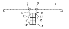
【解決手段】介護又は留守中の室内に関する各種の情報を送信することができる介護又は監視システムに用いられる介護補助用又は遠隔通信用制御ユニット1である。シーリングライト本体3の下面中央部に給電部材としての吊りフック10、11が固定され、吊りフック10、11の下部にあるフック部12、13(取付部材)を取り付け穴14、15にそれぞれ挿入することで、基板保持部材18を吊り下げることができる。また、基板保持部材18は、取り付け穴14、15の下面から下方へ延びる接続線を有しているので、シーリングライトの電源基板からフック部12、13及び接続線を介して制御用基板にDC電力を給電することができる。
【選択図】図3A care assisting or remote communication control unit that can be easily attached to a lighting device such as a ceiling light.
A care assisting or remote communication control unit for use in a nursing care or monitoring system capable of transmitting various types of information related to a room being nursing or absent. Hanging hooks 10 and 11 as power supply members are fixed to the center of the lower surface of the ceiling light main body 3, and hook portions 12 and 13 (attachment members) located below the hanging hooks 10 and 11 are inserted into the attachment holes 14 and 15, respectively. Thus, the substrate holding member 18 can be suspended. Moreover, since the board | substrate holding member 18 has the connection line extended below from the lower surface of the attachment holes 14 and 15, it is DC from the power supply board of a ceiling light to a control board via the hook parts 12 and 13 and a connection line. Electric power can be supplied.
[Selection] Figure 3
Description
本考案は、シーリングライト等の照明装置に取り付けることができる介護補助用又は遠隔通信用制御ユニットに関するものである。
具体的には、在宅障害者や寝たきりの高齢者等(以下「被介護者」という。)が簡単な操作で自身の音声又は画像を、遠距離にいる介護者のパソコンやスマートフォンへ送信することができ、逆に介護者も被介護者に対し自身の音声又は画像を送信することができ、また、留守中の遠隔監視を行うこともできるシステムに用いられる介護補助用又は遠隔通信用制御ユニットに関するものである。
The present invention relates to a care assisting or remote communication control unit that can be attached to a lighting device such as a ceiling light.
Specifically, a person with disabilities at home or a bedridden elderly person (hereinafter referred to as “caregiver”) can send his / her voice or image to a caregiver's computer or smartphone at a long distance with a simple operation. On the other hand, the caregiver can transmit his / her voice or image to the cared person, and can also perform remote monitoring while away from a care assisting or remote communication control unit. It is about.
障害者の数は日本全国で約750万人である。障害種別での施設入居者の割合を見てみると、身体障害者2.9%、精神障害者10.3%、知的障害者23.4%となっており、在宅障害者は全体的にも多くの割合を占める。
また、社会的な高齢化に伴い障害者の高齢化も進んでいる。例えば、在宅身体障害者のうち高齢者の割合は、65歳以上が221.1万人となり62%以上を占めている。
さらに、現在は健康でも高齢になるにつれて障害を持つ人も増加しており、2010年の調査では認知症280万人、寝たきり高齢者170万人となっている。2025年までには認知症500万人、寝たきり高齢者230万人になる予測がある。この背景に伴い、在宅介護補助システムは今後の最重要課題となっている。
There are approximately 7.5 million people with disabilities throughout Japan. Looking at the percentage of residents in facilities by type of disability, it was 2.9% physically disabled, 10.3% mentally disabled, and 23.4% mentally disabled. Also account for a large proportion.
In addition, with the aging of society, the disabled population is also aging. For example, the proportion of the elderly with physical disabilities at home is 2211,000 people 65 years or older, accounting for 62% or more.
In addition, the number of people with disabilities is increasing as they get older even though they are healthy. According to a 2010 survey, there are 2.8 million people with dementia and 1.7 million people who are bedridden. By 2025, it is predicted that there will be 5 million dementia and 2.3 million bedridden elderly people. With this background, the home care assistance system has become the most important issue in the future.
このような背景の下、節電を目的とした従来の光源から省電力で長寿命のLED光源への切り替えニーズがますます高まっている一方、シーリングライトは1998年の発売以来、リモートコントロールによる二段調光と常夜灯の機能が揃っているため、住宅を中心に普及しており、その数は約2000万個と推定されている。
そして、蛍光管式のシーリングライトについても、LED光源に比べ消費電力が大きいため、省電力や長寿命化の観点からLED化が進んでいる。
そこで、シーリングライト等を取り替える際に、合わせて介護補助用制御ユニットを取り付けることができるようにすれば、在宅介護補助システムを比較的容易に構築できる。
Against this backdrop, the need to switch from conventional light sources for power saving to LED light sources with longer power consumption has been increasing, while ceiling lights have been two-staged by remote control since its launch in 1998. Because it has the functions of dimming and nightlight, it is widely used mainly in houses, and the number is estimated to be about 20 million.
And since the fluorescent tube type ceiling light also consumes more power than the LED light source, the use of LEDs is progressing from the viewpoint of power saving and longer life.
Therefore, if a care assist control unit can be attached together when replacing a ceiling light or the like, a home care assist system can be constructed relatively easily.
特許文献1(特開2001−103454号公報、特に段落0005、0050及び図5)には、高齢者や身体障害者(以下、被介護者という。)の介護のために、被介護者の居室にテレビカメラを設置して室内の模様をテレビカメラで撮り、被介護者からは見えにくい場所に設置した映像モニタに映し出して異常や急変がないかを確認できるようにした介護システムについて紹介されているとともに、ランプが内蔵された天井直付け式の照明器具内にテレビカメラが下向きに設けられ、光透過性のカメラカバーを通して居室内の被介護者を撮影できるようにすることが記載されている。 Patent Document 1 (Japanese Patent Application Laid-Open No. 2001-103454, particularly paragraphs 0005 and 0050 and FIG. 5) describes a living room of a cared person for the care of an elderly person or a physically handicapped person (hereinafter referred to as a cared person). Introduced a nursing care system that installs a TV camera in the room and takes a picture of the interior of the room with a television camera and displays it on a video monitor installed in a place that is difficult for the care recipient to see whether there is any abnormality or sudden change. In addition, it is described that a TV camera is provided downward in a ceiling-mounted lighting fixture with a built-in lamp so that a cared person in the room can be photographed through a light-transmissive camera cover. .
また、シーリングライトにスピーカーを取り付け、無線通信回線を経由してスマートフォンにストックされている音楽を流すことができる近距離制御照明器具や、スマートフォンで照明器具の発光色の変更が可能なシーリングライト等も市販されているが、照明器具にスピーカー、照明、カメラ機能だけでなく様々な機能を有する介護補助用制御ユニットを取り付けられるようにしたものは存在しない。 In addition, a short-range control lighting device that can attach a speaker to the ceiling light and play music stocked on the smartphone via a wireless communication line, a ceiling light that can change the emission color of the lighting device on the smartphone, etc. However, there is no one that can attach a care assisting control unit having various functions in addition to the speaker, lighting, and camera functions to a lighting fixture.
本考案の課題は、シーリングライト等の照明装置に容易に取り付けることができる介護補助用又は遠隔通信用制御ユニットを提供することである。 An object of the present invention is to provide a care assisting or remote communication control unit that can be easily attached to a lighting device such as a ceiling light.
請求項1に係る考案の介護補助用又は遠隔通信用制御ユニットは、介護又は留守中の室内に関する各種の情報を送信することができる介護又は監視システムに用いられる介護補助用又は遠隔通信用制御ユニットであって、照明装置の電源装置と電気的に接続される給電線を有する給電部材と、複数の制御用基板を保持することが可能であるとともに、前記制御用基板と電気的に接続される接続線を有する基板保持部材を備え、前記給電部材は、前記照明装置に固定されるとともに、前記基板保持部材を着脱自在に取り付けるための取付部材を有し、該取付部材を用いて前記基板保持部材を前記給電部材に取り付けることによって、前記給電線と前記接続線が電気的に接続されるようになっていることを特徴とする。
The control unit for care assistance or remote communication of the device according to
請求項2に係る考案の介護補助用又は遠隔通信用制御ユニットは、請求項1に記載の介護補助用又は遠隔通信用制御ユニットにおいて、前記照明装置は本体の下面に半透明のPCカバーを有するシーリングライトであり、前記PCカバーの中央には穴が開けてあるとともに、前記給電部材は前記本体の下面中央部に固定されることを特徴とする。
The care assisting or remote communication control unit according to
請求項3に係る考案の介護補助用又は遠隔通信用制御ユニットは、請求項1に記載の介護補助用又は遠隔通信用制御ユニットにおいて、前記基板保持部材は、2つの半円筒状部材と、該2つの半円筒状部材を組み合わせて円筒状に固定するリング部材よりなり、前記2つの半円筒状部材は、上部中央に前記取付部材を受け入れる穴又は凹部を有し、前記接続線は、前記穴又は凹部の内面から前記半円筒状部材の下方へ延びていることを特徴とする。
The control unit for nursing assistance or remote communication according to
請求項4に係る考案の介護補助用又は遠隔通信用制御ユニットは、請求項1に記載の介護補助用又は遠隔通信用制御ユニットにおいて、前記基板保持部材は、2つの半円筒状部材と、該2つの半円筒状部材を組み合わせて円筒状に固定するリング部材よりなり、前記2つの半円筒状部材は、上部中央に前記取付部材に嵌合する突起を有し、前記接続線は、前記突起から前記半円筒状部材の下方へ延びていることを特徴とする。
The control unit for nursing assistance or remote communication of the device according to
請求項1に係る考案の介護補助用又は遠隔通信用制御ユニットは、照明装置の電源装置と電気的に接続される給電線を有する給電部材と、複数の制御用基板を保持することが可能であるとともに、制御用基板と電気的に接続される接続線を有する基板保持部材を備え、給電部材は、照明装置に固定されるとともに、基板保持部材を着脱自在に取り付けるための取付部材を有し、取付部材を用いて基板保持部材を給電部材に取り付けることによって、給電線と接続線が電気的に接続されるようになっているので、介護補助用又は遠隔通信用制御ユニットをシーリングライト等の照明装置に容易に取り付けることができ、また、基板保持部材を給電部材に取り付けるだけで、基板保持部材に保持されている制御用基板に照明装置の電源装置から給電することができる。
The care assisting or remote communication control unit of the invention according to
請求項2に係る考案によれば、請求項1に係る考案による効果に加え、照明装置は本体の下面に半透明のPCカバーを有するシーリングライトであり、PCカバーの中央には穴が開けてあるとともに、給電部材は本体の下面中央部に固定されるので、基板保持部材の下部をシーリングライトに開けてある穴と近接させ又は穴から突出させることができるので、画像撮影用カメラやマイクロフォンを基板保持部材の下部に設けることによって、鮮明な画像を撮影することができ、部屋内部の音を感度良く検知することができる。
また、シーリングライトに開けてある穴から外気を取り入れることができるので、基板保持部材に通気口を設けることで、制御用基板が発生する熱を逃がすという効果を奏することもできる。
According to the invention of
In addition, since the outside air can be taken in from the hole formed in the ceiling light, it is possible to provide an effect of releasing the heat generated by the control board by providing a vent hole in the board holding member.
請求項3に係る考案によれば、請求項1に係る考案による効果に加え、基板保持部材は、2つの半円筒状部材と、2つの半円筒状部材を組み合わせて円筒状に固定するリング部材よりなり、2つの半円筒状部材は、上部中央に取付部材を受け入れる穴又は凹部を有し、接続線は、穴又は凹部の内面から半円筒状部材の下方へ延びているので、基板保持部材を2つに分割して制御用基板を一方の半円筒状部材にセットし、その後他方の半円筒状部材を組み合わせてリング部材によって円筒状に固定することで、制御用基板を容易に交換したり追加したりすることができる。
また、接続線の構造が単純なので、製造し易い上に壊れにくく、給電線や制御用基板との電気的接続も確実に行われるという効果を奏する。
According to the invention of
Further, since the structure of the connection line is simple, it is easy to manufacture and is not easily broken, and there is an effect that the electrical connection with the power supply line and the control board is reliably performed.
請求項4に係る考案によれば、請求項1に係る考案による効果に加え、基板保持部材は、2つの半円筒状部材と、2つの半円筒状部材を組み合わせて円筒状に固定するリング部材よりなり、2つの半円筒状部材は、上部中央に取付部材に嵌合する突起を有し、接続線は、突起から半円筒状部材の下方へ延びているので、基板保持部材を2つに分割して制御用基板を一方の半円筒状部材にセットし、その後他方の半円筒状部材を組み合わせてリング部材によって円筒状に固定することで、制御用基板を容易に交換したり追加したりすることができる。
また、接続線の構造が単純なので、製造し易い上に壊れにくく、給電線や制御用基板との電気的接続も確実に行われるという効果を奏する。
According to the invention according to
Further, since the structure of the connection line is simple, it is easy to manufacture and is not easily broken, and there is an effect that the electrical connection with the power supply line and the control board is reliably performed.
実施例を説明する前に、介護又は監視システムの概要について説明する。
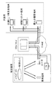
図1に示すように、被介護者や監視対象の居宅に、その居宅における音声や振動の検知、被介護者や居宅内の画像撮影、シーリングライト等の照明装置の制御、各種データの送受信を行う専用端末、介護補助用又は遠隔通信用制御ユニット及びルータを設置するともに、介護者等から被介護者等に対して音声、映像及び動画等の提供を行うテレビジョン受像機を設置する。
また、被介護者等の居宅と介護者等(介護サービス事業者、病院、ナースセンター、個人介護者及び警備サービス事業者等)の保有する端末との間はインターネット回線及びクラウドサーバーを利用して接続されており、クラウドサーバーによって各種データ(音声、振動、撮影画像、映像及び動画等)の管理やユーザー認証等の各種処理が行われる。
なお、居宅内における専用端末、介護補助用又は遠隔通信用制御ユニット及びルータ間のデータの送受信は、各種無線通信手段又は有線通信手段を利用できるが、Wifi等の無線LANを利用するのが設置作業の容易さやコスト等の面で有利である。
そして、本考案はこのような介護又は監視システムにおいて、シーリングライト等の照明装置に設置される介護補助用又は遠隔通信用制御ユニットに関する。
以下、実施例によって本考案の実施形態を説明する。
Before describing the embodiment, an outline of the care or monitoring system will be described.
As shown in FIG. 1, voice and vibration detection in a home to be cared for and a home to be monitored, image capturing in the home for the caregiver and home, control of a lighting device such as a ceiling light, and transmission and reception of various data A dedicated terminal to perform, a care assisting or remote communication control unit and a router are installed, and a television receiver for providing voice, video, video, and the like from a caregiver to a care recipient is installed.
In addition, between the homes of care recipients and caregivers (care service providers, hospitals, nurse centers, personal caregivers, security service providers, etc.) Connected, and various processes such as management of various data (sound, vibration, captured image, video, video, etc.) and user authentication are performed by the cloud server.
In addition, various wireless communication means or wired communication means can be used for transmission / reception of data between the dedicated terminal in the home, the care assisting or remote communication control unit, and the router, but it is installed using a wireless LAN such as WiFi. This is advantageous in terms of ease of work and cost.
The present invention relates to a care assisting or remote communication control unit installed in a lighting device such as a ceiling light in such a care or monitoring system.
Hereinafter, embodiments of the present invention will be described by way of examples.
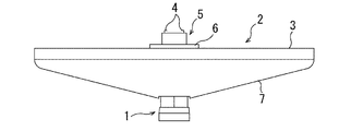
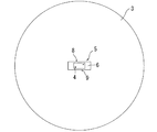
実施例1の介護補助用又は遠隔通信用制御ユニット1を取り付けたシーリングライト2の側面図を図2に、同介護補助用又は遠隔通信用制御ユニット1を取り付けたシーリングライト本体3の断面図を図3に、シーリングライト本体3の平面図を図4に、シーリングライト本体3の底面図を図5に示す。
FIG. 2 is a side view of the
図2に示すようにシーリングライト2に介護補助用又は遠隔通信用制御ユニット1を取り付けた状態においては、シーリングライト2の中央下面から介護補助用又は遠隔通信用制御ユニット1の下部が突出するようになっており、居宅内の画像撮影がし易い構造となっている。
また、シーリングライト本体3は、図2及び図4に示すように、天井面に設置されている引掛けシーリング(図示せず)に、引掛刃4を用いて固定できる引掛シーリングアダプター5の平板部6へネジ等の適宜の手段によって取り付けられる。
そして、シーリングライト本体3には、その下面中央部に介護補助用又は遠隔通信用制御ユニット1が固定されるとともに、その下面全体を覆い中央部に介護補助用又は遠隔通信用制御ユニット1を通過させることが可能な穴を開けてある半透明のPCカバー7が固定できるようになっている。
As shown in FIG. 2, when the care assisting or remote
Further, as shown in FIGS. 2 and 4, the ceiling
The ceiling light
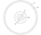
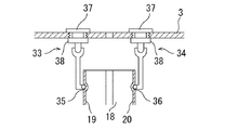
シーリングライト本体3の下面中央部に介護補助用又は遠隔通信用制御ユニット1を固定するための構造は、図3〜5に示すように、シーリングライト本体3の中央部に設けられている2つの固定用穴8、9の下側に吊りフック10、11が固定され、吊りフック10、11の下部にあるフック部12、13(取付部材)を基板保持部材18の上部に設けられている取り付け穴14、15にそれぞれ挿入することで、吊りフック10、11の下に基板保持部材18を吊り下げられるようにしたものである。
また、シーリングライト本体3の下面には、引掛シーリングアダプター5を介して供給されるAC電力をDC電力に変換するための電源基板16及び電源基板16からのDC電力を給電することで発光するLEDを多数搭載しているLED発光素子基板17が設置されている。
なお、電源基板16はLEDだけでなく、介護補助用又は遠隔通信用制御ユニット1にもDC電力を給電する。
As shown in FIGS. 3 to 5, the structure for fixing the care assisting or remote
Further, on the lower surface of the ceiling
The
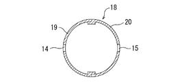
実施例1の介護補助用又は遠隔通信用制御ユニット1の基板保持部材18を横方向に切った断面図を図6に、同介護補助用又は遠隔通信用制御ユニット1の基板保持部材18を縦方向に切った断面図を図7に、基板保持部材18を構成する2つの半円筒状部材19、20を組み合わせて円筒状に固定するリング部材21の断面図を図8に、円筒状に固定された2つの半円筒状部材19、20の下端部にねじ込む底蓋22の断面図を図9に示す。
FIG. 6 is a cross-sectional view of the nursing support or remote
図6〜9に示すように、基板保持部材18は、2つの半円筒状部材19、20、リング部材21及び底蓋22からなっている。
2つの半円筒状部材19、20は、それぞれ上部中央にフック部12、13を受け入れる取り付け穴14、15、下部の周囲にリング部材21を受け止めるテーパー部23、24、下端部の周囲に底蓋22をねじ込むネジ山25、26、取り付け穴14、15の下面から半円筒状部材19、20の下方へ延びる接続線27、28及び内面に設けられる複数本の基板固定用溝29、30を有している。
そして、2つの半円筒状部材19、20で制御用基板(図示せず)を基板固定用溝29、30の間に挟持しながら図6のように組み合わせ、上部からリング部材21を挿入し、テーパー部23、24で受け止められるまでスライドさせ、その状態で底蓋22をネジ山25、26へねじ込むと基板保持部材18が組み上がるようになっている。
As shown in FIGS. 6 to 9, the
The two
Then, the control board (not shown) is sandwiched between the
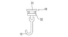
図10は、給電部材としての吊りフック10を拡大した図であり、シーリングライト本体3の固定用穴8に上部から差し込まれる差し込みネジ31と差し込みネジ31にねじ込まれる固定ネジ32からなっている。
そして、差し込みネジ31に固定ネジ32をねじ込む際に、電源基板16と接続されているDC連接ワイヤ(図示せず)を挟み込むことで、固定ネジ32、フック部12及び接続線27を介して制御用基板にDC電力が給電できるようになっている。
なお、吊りフック11も吊りフック10と全く同じ構造であり、差し込みネジ31に固定ネジ32をねじ込む際に、電源基板16と接続されているDC連接ワイヤを挟み込むことで、固定ネジ32、フック部13及び接続線28を介して制御用基板にDC電力を給電することができる。
FIG. 10 is an enlarged view of the hanging
When the fixing
The hanging
以下の説明において、実施例1と変わっていない箇所については、実施例1と同じ番号を用いる。
実施例2の介護補助用又は遠隔通信用制御ユニット33と実施例1の介護補助用又は遠隔通信用制御ユニット1との違いは、吊りフック10、11に代えてロックピン33、34を給電部材として用いる点と、基板保持部材18の取り付け穴14、15に代えて取り付け凹部35、36とした点である。
In the following description, the same numbers as those in the first embodiment are used for portions that are not different from those in the first embodiment.
The difference between the care assisting or remote
ロックピン33、34は、図11に示すように、吊りフック10、11の差し込みネジ31と同じ構造の差し込みネジ37と差し込みネジ37にねじ込まれる固定ネジ38からなっており、2つのロックピン33、34の先端(取付部材)を取り付け凹部35、36に嵌合させ、両側から挟み込むことで基板保持部材18を固定するようにしている。
そして、接続線27、28は、取り付け凹部35、36の内面から基板保持部材18を貫通し、半円筒状部材19、20の下方へ延びているので、差し込みネジ37に固定ネジ38をねじ込む際に、電源基板16と接続されているDC連接ワイヤを挟み込むことで、固定ネジ38及び接続線27又は固定ネジ38及び接続線28を介して制御用基板にDC電力を給電することができる。
As shown in FIG. 11, the lock pins 33 and 34 include an
Since the connecting
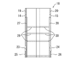
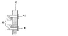
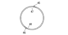
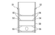
実施例3の制御ユニット固定部材40をシーリングライト本体3に取り付ける時の断面図を図12に、制御ユニット固定部材40を縦方向に切った断面図を図13に、実施例3の基板保持部材取り付け部分の拡大正面図を図14に、実施例3の基板保持部材取り付け部分を縦方向に切った拡大断面図を図15に、実施例3の制御ユニット固定部材40を横方向に切った断面図を図16に、実施例3の基板保持部材50を縦方向に切った断面図を図17に示す。
12 is a sectional view when the control
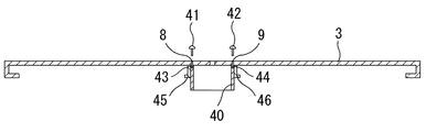
実施例3の介護補助用又は遠隔通信用制御ユニットは、図12及び図13に示す給電部材としての制御ユニット固定部材40と、図17に示す基板保持部材50よりなり、制御ユニット固定部材40は、図12に示すようにシーリングライト本体3の中央部に設けられている2つの固定用穴8、9の上部からネジ41、42をネジ穴43、44にねじ込むことによってシーリングライト本体3の下面に固定され、基板保持部材50は、図17に示すように側面上部に設けられている導電性の突起51、52を、それぞれ図16に示すL字状の溝47、48(取付部材)に差し込んで固定できるようになっている。
The control unit for care support or remote communication according to the third embodiment includes a control
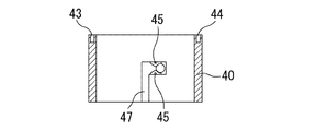
実施例3の制御ユニット固定部材40は、図13及び図16に示すように、内面側にL字状の溝47、48を対向位置から少しずらして設けてある。
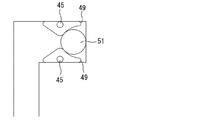
図14はL字状の溝47の拡大図であり、図15は制御ユニット固定部材40の外側から打ち込まれる2本の導電性の釘45を通る面で切った断面図である。
図14及び図15に示すように、L字状の溝47の奥側には2本の釘45が貫通しているとともに、弾力性のある略三角形の導電性部材49が釘45と接触するように設けてある。また、L字状の溝48もL字状の溝47と同様の構造となっているので、導電性の突起51、52をL字状の溝47、48に下方から差し込んだ後、上方から見て時計回り(下方からみて反時計回り)に回転させると、導電性の突起51、52は、2つの導電性部材49を変形させながら、それぞれ2本の釘45及び2本の釘46の間を通り抜けてL字状の溝47、48の奥に入り込み、2つの導電性部材49に挟まれた状態で固定される。
As shown in FIGS. 13 and 16, the control
FIG. 14 is an enlarged view of the L-shaped
As shown in FIGS. 14 and 15, two
実施例3の基板保持部材50は、基本的な構造は実施例1及び2の基板保持部材18とほぼ同じであり、2つの半円筒状部材19、20、リング部材21及び底蓋22からなっている(図17では省略)。
実施例1及び2の基板保持部材18との違いは、取り付け穴14、15や、取り付け凹部35、36に代えて、L字状の溝47、48に対応する位置に導電性の突起51、52が設けられている点である。
そして、突起51、52には半円筒状部材19、20の下方へ延びる接続線53、54が接続されているので、基板固定用溝55、56の間に挟持される制御用基板に、釘45、46、導電性部材49、導電性の突起51、52及び接続線53、54を介してDC電力を給電することができる。
The basic structure of the substrate holding member 50 according to the third embodiment is substantially the same as the
The difference from the
Since the
実施例1〜3の変形例を列記する。
(1)実施例1〜3の介護補助用又は遠隔通信用制御ユニットは、被介護者の介護補助や居宅の警備を目的とした介護又は監視システムの一部を構成するものであるが、介護又は監視システムの目的は介護補助や警備に限らず、火事やガス漏れの検知、ペットの遠隔監視、ペットとの遠隔コミュニケーション、居宅内にある電気製品の制御(オンオフ、タイマーセット及び番組予約等)を対象とするものであっても良い。
そして、システムの目的に応じて各種データの送信先は異なることとなる。例えば、火事やガス漏れの検知であればセキュリティーサービス事業者、居宅のオーナーや居住者の保有する端末、ペットの遠隔監視やペットとの遠隔コミュニケーションであればペットショップやペット所有者の保有する端末、居宅内にある電気製品の制御であれば居住者の保有する端末となる。
(2)実施例1〜3の介護補助用又は遠隔通信用制御ユニットは、いずれもシーリングライト本体3の下面に取り付けるものであるが、平らな板を有する照明装置であれば、どのようなものであっても取り付けることができる。
また、介護補助用又は遠隔通信用制御ユニットを取り付けた時、下部が照明装置の外側に突出する例を図2に示したが、全体が照明装置の外側に位置しても良いし、逆に全体が照明装置のフードの内側に位置するようにしても良い。ただし、全体が照明装置のフードの内側に位置する場合、画像撮影用カメラのレンズ部分に近いフード部分は透明又は透孔とする必要がある。
(3)実施例1〜3の介護補助用又は遠隔通信用制御ユニットは、各種データの送受信を行うことが可能なものとなっているが、受信は可能である必要はなく、各種データを介護者に一方向に送信できるだけのものであっても良い。
(4)実施例1〜3の基板保持部材は、2つの半円筒状部材19、20を組み合わせて円筒状に固定するリング部材21と、ネジ山25、26へねじ込む底蓋22を有しているが、リング部材21だけで固定することが可能であるので、底蓋22やネジ山25、26はなくても良い。
The modification of Examples 1-3 is listed.
(1) The control unit for assisting care or remote communication of Examples 1 to 3 constitutes a part of the care or monitoring system for the purpose of assisting care of the care recipient or security of the home, The purpose of the monitoring system is not limited to nursing assistance and security, but it can detect fires and gas leaks, remotely monitor pets, communicate remotely with pets, and control appliances in the home (on / off, timer set, program reservation, etc.) It may be a target.
The transmission destinations of various data differ depending on the purpose of the system. For example, if a fire or gas leak is detected, a security service provider, a terminal owned by a homeowner or resident, a pet shop or a terminal owned by a pet owner for remote monitoring of pets or remote communication with pets If it is the control of the electrical product in the house, it becomes a terminal owned by the resident.
(2) The care assisting or remote communication control units of the first to third embodiments are all attached to the lower surface of the ceiling
Moreover, although the example which the lower part protrudes outside the illuminating device when the control unit for care assistance or telecommunications is attached is shown in FIG. 2, the whole may be located outside the illuminating device. The whole may be located inside the hood of the lighting device. However, when the entirety is located inside the hood of the lighting device, the hood portion close to the lens portion of the image capturing camera needs to be transparent or through-holed.
(3) The control unit for assisting care or remote communication in Examples 1 to 3 is capable of transmitting and receiving various data, but it is not necessary to be able to receive and care for various data. It may be possible to transmit to a person in one direction.
(4) The substrate holding members of Examples 1 to 3 have a
1 介護補助用又は遠隔通信用制御ユニット 2 シーリングライト
3 シーリングライト本体 4 引掛刃
5 引掛シーリングアダプター 6 平板部 7 PCカバー
8、9 固定用穴 10、11 吊りフック 12、13 フック部
14、15 取り付け穴 16 電源基板 17 LED発光素子基板
18 基板保持部材 19、20 半円筒状部材 21 リング部材
22 底蓋 23、24 テーパー部 25、26 ネジ山
27、28 接続線 29、30 基板固定用溝
31 差し込みネジ 32 固定ネジ 33、34 ロックピン
35、36 取り付け凹部 37 差し込みネジ 38 固定ネジ
40 制御ユニット固定部材 41、42 ネジ 43、44 ネジ穴
45、46 釘 47、48 L字状の溝 49 導電性部材
50 基板保持部材 51、52 突起 53、54 接続線
55、56 基板固定用溝
DESCRIPTION OF
50
Claims (4)
照明装置の電源装置と電気的に接続される給電線を有する給電部材と、
複数の制御用基板を保持することが可能であるとともに、前記制御用基板と電気的に接続される接続線を有する基板保持部材を備え、
前記給電部材は、前記照明装置に固定されるとともに、前記基板保持部材を着脱自在に取り付けるための取付部材を有し、該取付部材を用いて前記基板保持部材を前記給電部材に取り付けることによって、前記給電線と前記接続線が電気的に接続されるようになっている
ことを特徴とする介護補助用又は遠隔通信用制御ユニット。 A control unit for nursing care assistance or remote communication used in a nursing care or monitoring system capable of transmitting various types of information related to the room being nursing or absent,
A power supply member having a power supply line electrically connected to the power supply device of the lighting device;
It is possible to hold a plurality of control boards, and includes a board holding member having a connection line electrically connected to the control board,
The power supply member is fixed to the lighting device and has an attachment member for detachably attaching the substrate holding member, and by attaching the substrate holding member to the power supply member using the attachment member, The power supply line and the connection line are electrically connected to each other. A care assisting or remote communication control unit, wherein:
前記PCカバーの中央には穴が開けてあるとともに、
前記給電部材は前記本体の下面中央部に固定される
ことを特徴とする請求項1記載の介護補助用又は遠隔通信用制御ユニット。 The lighting device is a ceiling light having a translucent PC cover on the lower surface of the main body,
There is a hole in the center of the PC cover,
The care supply or remote communication control unit according to claim 1, wherein the power supply member is fixed to a central portion of the lower surface of the main body.
2つの半円筒状部材と、
該2つの半円筒状部材を組み合わせて円筒状に固定するリング部材よりなり、
前記2つの半円筒状部材は、上部中央に前記取付部材を受け入れる穴又は凹部を有し、
前記接続線は、前記穴又は凹部の内面から前記半円筒状部材の下方へ延びている
ことを特徴とする請求項1記載の介護補助用又は遠隔通信用制御ユニット。 The substrate holding member is
Two semi-cylindrical members;
A ring member that combines the two semi-cylindrical members and fixes them in a cylindrical shape,
The two semi-cylindrical members have a hole or a recess for receiving the mounting member in the upper center,
The care support or remote communication control unit according to claim 1, wherein the connection line extends from the inner surface of the hole or the recess to the lower side of the semi-cylindrical member.
2つの半円筒状部材と、
該2つの半円筒状部材を組み合わせて円筒状に固定するリング部材よりなり、
前記2つの半円筒状部材は、上部中央に前記取付部材に嵌合する突起を有し、
前記接続線は、前記突起から前記半円筒状部材の下方へ延びている
ことを特徴とする請求項1記載の介護補助用又は遠隔通信用制御ユニット。 The substrate holding member is
Two semi-cylindrical members;
A ring member that combines the two semi-cylindrical members and fixes them in a cylindrical shape,
The two semi-cylindrical members have a protrusion that fits into the mounting member in the upper center,
The control unit for care assistance or remote communication according to claim 1, wherein the connection line extends from the protrusion to below the semi-cylindrical member.
Publications (1)
| Publication Number | Publication Date |
|---|---|
| JP3191663U true JP3191663U (en) | 2014-07-03 |
Family
ID=
Similar Documents
| Publication | Publication Date | Title |
|---|---|---|
| RU2711034C2 (en) | Intelligent device for fast connection of electrical equipment | |
| US20220003399A1 (en) | Modular smart quick connect device for electrical fixtures | |
| US20250357659A1 (en) | Control Module for a Lighting Fixture | |
| CN106687933B (en) | System and method for emergency exit and monitoring system | |
| US20160073479A1 (en) | Modular illumination device and associated systems and methods | |
| US11152794B2 (en) | Multipurpose electrical fixtures | |
| US20100296685A1 (en) | Adapter and electronic devices for recessed light socket | |
| US10436422B1 (en) | Multi-function active accessories for LED lamps | |
| US8963426B2 (en) | LED light | |
| JP2006113752A (en) | lighting equipment | |
| US20200007359A1 (en) | System and method for beacon | |
| JP6654767B1 (en) | LED lighting system | |
| JP2022100401A (en) | Remote monitoring system, information processing device, program and adapter device | |
| JP3191663U (en) | Nursing care control unit or remote communication control unit | |
| JP2018195470A (en) | LED lighting device | |
| WO2016057752A1 (en) | Illumination systems and associated components | |
| JP2011258533A (en) | Led illumination lamp and management system of the same | |
| US20100244568A1 (en) | Lighting module with wireless alternating current detection system | |
| JP2010114055A (en) | Led lighting fixture | |
| CN102162582A (en) | Lighting body provided with integrated intelligence | |
| JP2015095420A (en) | Illumination control device and illumination system | |
| JP7644529B2 (en) | Lighting equipment | |
| JP6986695B2 (en) | Lighting equipment and lighting system | |
| KR100512380B1 (en) | Support member for fire extinguisher of appartment house | |
| TWI676765B (en) | Lamp appartus for multiple applications |