JP3188317U - Portable power supply for area-based charging and area series discharging - Google Patents
Portable power supply for area-based charging and area series discharging Download PDFInfo
- Publication number
- JP3188317U JP3188317U JP2013006177U JP2013006177U JP3188317U JP 3188317 U JP3188317 U JP 3188317U JP 2013006177 U JP2013006177 U JP 2013006177U JP 2013006177 U JP2013006177 U JP 2013006177U JP 3188317 U JP3188317 U JP 3188317U
- Authority
- JP
- Japan
- Prior art keywords
- battery
- area
- opening
- series
- charging
- Prior art date
- Legal status (The legal status is an assumption and is not a legal conclusion. Google has not performed a legal analysis and makes no representation as to the accuracy of the status listed.)
- Expired - Fee Related
Links
Images

Classifications
-
- H—ELECTRICITY
- H02—GENERATION; CONVERSION OR DISTRIBUTION OF ELECTRIC POWER
- H02J—ELECTRIC POWER NETWORKS; CIRCUIT ARRANGEMENTS OR SYSTEMS FOR SUPPLYING OR DISTRIBUTING ELECTRIC POWER; SYSTEMS FOR STORING ELECTRIC ENERGY
- H02J7/00—Circuit arrangements for charging or discharging batteries or for supplying loads from batteries
- H02J7/50—Circuit arrangements for charging or discharging batteries or for supplying loads from batteries acting upon multiple batteries simultaneously or sequentially
- H02J7/52—Circuit arrangements for charging or discharging batteries or for supplying loads from batteries acting upon multiple batteries simultaneously or sequentially for charge balancing, e.g. equalisation of charge between batteries
- H02J7/56—Active balancing, e.g. using capacitor-based, inductor-based or DC-DC converters
-
- H—ELECTRICITY
- H02—GENERATION; CONVERSION OR DISTRIBUTION OF ELECTRIC POWER
- H02J—ELECTRIC POWER NETWORKS; CIRCUIT ARRANGEMENTS OR SYSTEMS FOR SUPPLYING OR DISTRIBUTING ELECTRIC POWER; SYSTEMS FOR STORING ELECTRIC ENERGY
- H02J7/00—Circuit arrangements for charging or discharging batteries or for supplying loads from batteries
- H02J7/50—Circuit arrangements for charging or discharging batteries or for supplying loads from batteries acting upon multiple batteries simultaneously or sequentially
- H02J7/575—Parallel/serial switching of connection of batteries to charge or load circuit
-
- Y—GENERAL TAGGING OF NEW TECHNOLOGICAL DEVELOPMENTS; GENERAL TAGGING OF CROSS-SECTIONAL TECHNOLOGIES SPANNING OVER SEVERAL SECTIONS OF THE IPC; TECHNICAL SUBJECTS COVERED BY FORMER USPC CROSS-REFERENCE ART COLLECTIONS [XRACs] AND DIGESTS
- Y02—TECHNOLOGIES OR APPLICATIONS FOR MITIGATION OR ADAPTATION AGAINST CLIMATE CHANGE
- Y02E—REDUCTION OF GREENHOUSE GAS [GHG] EMISSIONS, RELATED TO ENERGY GENERATION, TRANSMISSION OR DISTRIBUTION
- Y02E60/00—Enabling technologies; Technologies with a potential or indirect contribution to GHG emissions mitigation
- Y02E60/10—Energy storage using batteries
Landscapes
- Engineering & Computer Science (AREA)
- Power Engineering (AREA)
- Charge And Discharge Circuits For Batteries Or The Like (AREA)
- Secondary Cells (AREA)
Abstract
【課題】入力された電力をそれぞれ独立して各電池に蓄電し、使用時には、各電池による直列放電を行う、エリア分け充電及びエリア直列放電が可能なポータブル型電源を提供する。
【解決手段】第一電池10と、第二電池20と、第一開閉部品30と、複数の充電レギュレータ電子回路40と、第二開閉部品60と、入力インターフェイス70部品と、出力インターフェイス部品80とからなる。第二電池は第一電池と直列方式で接続する。第一開閉部品は第一電池と第二電池の間に設けられる。充電レギュレータ電子回路は第一電池及び第二電池と接続する。第二開閉部品は第二電池と接続すると共に選択的に開閉する。入力インターフェイス部品は一端に外部電源と連結される入力連結部が設けられ、他端が充電レギュレータ電子回路と接続する。出力インターフェイス部品は一端に外部電子装置と連結される出力連結部が設けられ、他端が第一電池及び第二電池と接続する。
【選択図】図1Provided is a portable power source capable of area-by-area charging and area series discharge, in which input power is stored in each battery independently, and when used, each battery performs series discharge.
A first battery, a second battery, a first opening / closing component, a plurality of charge regulator electronic circuits, a second opening / closing component, an input interface component, and an output interface component. Consists of. The second battery is connected in series with the first battery. The first opening / closing component is provided between the first battery and the second battery. The charge regulator electronics are connected to the first battery and the second battery. The second opening / closing component is connected to the second battery and selectively opens and closes. One end of the input interface component is connected to an external power source, and the other end is connected to the charging regulator electronic circuit. One end of the output interface component is provided with an output connecting portion connected to the external electronic device, and the other end is connected to the first battery and the second battery.
[Selection] Figure 1
Description
本考案は、ポータブル型電源に関し、特に、蓄電時には、入力された電力をそれぞれ独立して各電池に蓄電し、使用時には、各電池による直列放電を行う、エリア分け充電及びエリア直列放電を行うポータブル型電源に関する。 The present invention relates to a portable power supply, and in particular, when storing electricity, each input power is stored in each battery independently, and when used, a series discharge is performed by each battery. Type power supply.
近年、スマートフォン、タブレット型パソコン、或いはノート型パソコン等の各種デジタル電化製品の目覚しい進歩に伴い、モバイル電源の需要が高まっている。同時に、電池規格に対する要求も日増しに厳しくなっている。例えば、貯蔵電量は倍増し続け、出力電圧も絶えず上昇している。このような需要の中で、二つ、及び二つ以上の電池を直並列組合せで使用することは、現在既に最も一般的なモデルとなっている。例えば、車両用電化製品は、必要な動作電圧が12V以上である。また、一部のノート型パソコンや、大サイズのタブレット型パソコン、電動工具、デジタルオーディオ等の電化製品も、その多くにおいて、必要な動作電圧が12V以上である。しかし、各々の電池の特性には違いがあるため、消費者が使用する際や、製造メーカーが製造する際に、種々の困難を招くとともに、コストが増加する。 In recent years, with the remarkable progress of various digital appliances such as smartphones, tablet computers, and notebook computers, the demand for mobile power sources is increasing. At the same time, demands for battery standards are getting stricter. For example, the stored energy continues to double and the output voltage is constantly rising. Among these demands, the use of two and two or more batteries in a series-parallel combination has already become the most common model. For example, a vehicle appliance has a required operating voltage of 12V or higher. In addition, some notebook computers, large-sized tablet computers, electric tools, electric appliances such as digital audio, etc. have a required operating voltage of 12 V or more. However, since there is a difference in the characteristics of each battery, various difficulties are caused and the cost increases when used by consumers or manufactured by manufacturers.
従来のモバイル電源には、以下の欠点がある。 Conventional mobile power sources have the following drawbacks.
1.充電元電源による制限として、従来のリチウム関連材質の電池は、電池の充電電圧が直列数量に応じて倍増し、二直列では8.4Vより大きく、三直列では12.6V、四直列では更に16.8Vに達することが求められる。必要な電圧、及び以下の要因による制限のため、使用者がいつでもどこでも充電できるという利便性が損なわれている。 1. As a limitation of the charging source power supply, the battery of the conventional lithium-related material doubles the charging voltage of the battery according to the series quantity, is larger than 8.4V in two series, 12.6V in three series, and further 16 in four series. .8V is required to be reached. Due to the required voltage and the limitations due to the following factors, the convenience that the user can charge anytime and anywhere is impaired.
1−1.専用規格の変圧器しか使うことができず、且つ都市電気が提供されている場所でのみ充電が可能である。 1-1. Only a transformer with a dedicated standard can be used, and charging is possible only at a place where city electricity is provided.
1−2.二直列以外の組み合わせは、車載充電を行うことができない。 1-2. In-vehicle charging is not possible with combinations other than two series.
1−3.パソコンのUSBを使用した充電、及び市場でよく用いられる5V Micro−USB Adapter(レギュレータ充電器)による充電を行うことができない。 1-3. Charging using a USB of a personal computer and charging with a 5V Micro-USB Adapter (regulator charger) often used in the market cannot be performed.
1−4.特別製の太陽光パネルを除いて、一般的な規格の5V低圧太陽光パネルによる充電を行うことができない。 1-4. Except for specially made solar panels, charging with a standard 5V low-voltage solar panel is not possible.
2.製造時における制限として、従来の電池ユニットは、2・3・4といった直並列組合せを製造する際に以下の問題がある。 2. As a limitation at the time of manufacture, the conventional battery unit has the following problems when manufacturing series-parallel combinations such as 2, 3, and 4.
2−1.各ユニットの電池は、それぞれ個別に選別しなければならず、特性の近い電池しか直列電池ユニットとして組み合わせることができない。つなぐ数が多い組み合わせほど、特性が同等の電池を選ぶことが難しくなり、これに伴い材料調達や製造コストが上昇する。 2-1. The batteries of each unit must be individually selected, and only batteries with similar characteristics can be combined as a series battery unit. As the number of connections increases, it becomes more difficult to select batteries having the same characteristics, which increases material procurement and manufacturing costs.
2−2.つなぐ数の多い電池ユニットは、充電の電子回路がより複雑になる。一つ一つの電池の充電状態を常に監視制御することにより、電池間の充電不均衡による危険の発生を防がなければならないため、より多くの電子部品を組み合わせることで電池を保護する必要がある。この他、同時にコストも上昇する。 2-2. The battery unit with a large number of connections has a more complicated electronic circuit for charging. By constantly monitoring and controlling the state of charge of each battery, it is necessary to prevent the occurrence of danger due to imbalanced charging between batteries, so it is necessary to protect the battery by combining more electronic components. . In addition, the cost increases at the same time.
3.環境保護における制限として、従来の二直列及び二直列以上の電池ユニットは、いずれか一つの電池が故障すると、電池ユニット全体を廃棄処分しなければならなくなる。 3. As a limitation in environmental protection, when any one of the conventional two-series and two-series or more battery units fails, the entire battery unit must be disposed of.
上述の欠点に鑑み、本考案は、各直列電池を独立して充電するとともに各直列電池が整合的に放電を行う構造を採用することにより、どのような蓄電池にも適用でき、例えばリチウム電池の場合、二直列或いはそれ以上の多直列リチウム電池ユニットかを問わず、一つ一つの必要とする充電電圧が4.2Vより大きければよいため、非常に一般的な出力規格である5V以上の出力を有する機器さえあれば各電池を充電可能であり、例えばパソコンのUSB、及び市場でよく用いられる5V Micro−USB Adapter(レギュレータ充電器)、及び車内備え付けの12V出力着火器のいずれによっても充電が可能なことにより、使用者がいつでもどこでも充電することができる、エリア分け充電及びエリア直列放電を行うポータブル型電源を提供することを目的とする。 In view of the above-described drawbacks, the present invention can be applied to any storage battery by adopting a structure in which each series battery is charged independently and discharges in a consistent manner. In this case, regardless of whether it is a two-series or more multi-series lithium battery unit, it is sufficient that each required charging voltage is larger than 4.2V, so an output of 5V or more which is a very general output standard Each battery can be charged as long as there is a device equipped with a battery. For example, it can be charged by a USB of a personal computer, a 5V Micro-USB Adapter (regulator charger) often used in the market, and a 12V output igniter installed in the vehicle. Portable with area-based charging and area series discharge, allowing users to charge anywhere, anytime possible The purpose is to provide a mold power supply.
また、本考案は、使用するリチウム電池を特別に選別せずとも容量が同等であれば使用できるとともに、充電制御保護プレートを特製する必要がなく、且つ各エリアの電池が直接直列につながれていないため、いずれか一つの電池が故障しても、故障した電池だけを取り替えることができる、エリア分け充電及びエリア直列放電を行うポータブル型電源を提供することを目的とする。 In addition, the present invention can be used as long as the lithium batteries to be used have the same capacity without being specially selected, and it is not necessary to make a special charge control protection plate, and the batteries in each area are not directly connected in series. Therefore, it is an object of the present invention to provide a portable power source that performs area-by-area charging and area series discharge, in which even if any one of the batteries fails, only the failed battery can be replaced.
また、本考案は、複数直列(エリア)の電池構造において、充電時に複数直列(エリア)における高電圧ではなく単一直列(エリア)における低電圧によって充電を行うことができる、エリア分け充電及びエリア直列放電を行うポータブル型電源を提供することを目的とする。 In addition, the present invention provides a multi-series (area) battery structure in which charging can be performed with a low voltage in a single series (area) instead of a high voltage in a plurality of series (area) during charging. An object of the present invention is to provide a portable power source that performs series discharge.
上述の目的を達成するため、本考案のエリア分け充電及びエリア直列放電を行うポータブル型電源は、少なくとも一つの第一電池と、少なくとも一つの第二電池と、少なくとも一つの第一開閉部品と、複数の充電レギュレータ電子回路と、少なくとも一つの第二開閉部品と、一つの入力インターフェイス部品と、出力インターフェイス部品とからなる。第二電池は、第一電池と直列方式によって電気的に接続する。第一開閉部品は、第一電池と第二電池の間に設けられる。充電レギュレータ電子回路は、それぞれ第一電池及び第二電池と電気的に接続する。第二開閉部品は、それぞれ第一電池及び第二電池と電気的に接続するとともに、第二開閉部品は、選択的に開閉する。入力インターフェイス部品は、その一端に少なくとも一つの入力連結部が設けられ、入力連結部に対する他端が各充電レギュレータ電子回路と電気的に接続する。入力連結部は、外部電源と連結される。出力インターフェイス部品は、その一端に少なくとも一つの出力連結部が設けられ、出力連結部に対する他端が第一電池及び第二電池と電気的に接続する。出力連結部は、外部電子装置と連結される。 In order to achieve the above-mentioned object, a portable power source that performs area-division charging and area series discharge according to the present invention includes at least one first battery, at least one second battery, and at least one first opening / closing component. A plurality of charge regulator electronic circuits, at least one second opening / closing component, one input interface component, and an output interface component. The second battery is electrically connected to the first battery in a series manner. The first opening / closing component is provided between the first battery and the second battery. The charge regulator electronics are electrically connected to the first battery and the second battery, respectively. The second opening / closing component is electrically connected to the first battery and the second battery, respectively, and the second opening / closing component is selectively opened and closed. The input interface component is provided with at least one input coupling portion at one end, and the other end with respect to the input coupling portion is electrically connected to each charging regulator electronic circuit. The input connection unit is connected to an external power source. The output interface component is provided with at least one output connecting portion at one end thereof, and the other end with respect to the output connecting portion is electrically connected to the first battery and the second battery. The output connection unit is connected to an external electronic device.
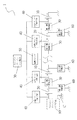
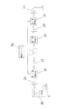
まず、図1及び図2を参照する。本考案のエリア分け充電及びエリア直列放電を行うポータブル型電源1は、少なくとも一つの第一電池10と、少なくとも一つの第二電池20と、少なくとも一つの第一開閉部品30と、複数の充電レギュレータ電子回路40と、一つの電源スイッチ50と、少なくとも一つの第二開閉部品60と、一つの入力インターフェイス部品70と、一つの入力インターフェイス部品80とからなる。
First, FIG. 1 and FIG. 2 will be referred to. The
第一電池10は、充電電池である。
The
第二電池20は、充電電池であるとともに、第一電池10と直列方式によって電気的に接続する。
The
上述した第一電池10及び第二電池20は、それぞれが一つのエリアをなすか、或いは、それぞれが複数の直列電池ユニットからなるとともに一つのエリアをなす。また、電池の数量によって制限されない。
Each of the
第一開閉部品30は、第一電池10と第二電池20の間に設けられるとともに、第一開閉部品30の一端は第一電池の正極と電気的に接続し、他端は第二電池20の負極と電気的に接続する(図1を参照)。
The first opening /
充電レギュレータ電子回路40は、それぞれ第一電池10及び第二電池20の正極と電気的に接続する。充電レギュレータ電子回路40は、出力電圧を安定させる機能を有し、通電時において、第一電池10及び第二電池20の電圧を安定させる。
The charge regulator
電源スイッチ50は、第一開閉部品30と電気的に接続し、電源スイッチ50を起動すると同時に各第一開閉部品30を起動することにより、第一電池10及び第二電池20を直列放電状態にする。
The
第二開閉部品60は、第二電池20と電気的に接続する(一端は接地する)。第二開閉部品60が充電時に起動することにより、各充電レギュレータ電子回路40と各第二電池20と各第二開閉部品60とが連通した電子回路を形成し、それぞれ充電を行う。
The second opening /
上述した第一開閉部品30及び第二開閉部品60は、それぞれMOS電子部品・トランジスタ・継電器・半導体或いは機械切換スイッチのいずれか一種である。上述で挙げた数種は例であり、これによって制限されるものではない。
The first opening /
本考案は、電池の数量を制限しない。一つから数個の電池を直列につなぐとともに、これに対応する数量の充電レギュレータ電子回路40と第一開閉部品30と第二開閉部品60とを組み合わせることができる。
The present invention does not limit the number of batteries. One to several batteries can be connected in series, and the charge regulator
上述した各充電レギュレータ電子回路40は、それぞれ各第一電池10及び各第二電池20の正極と電気的に接続する。各第二開閉部品60は、それぞれ各第一電池10及び各第二電池20の負極と電気的に接続する。
Each charge regulator
入力インターフェイス部品70は、その一端に少なくとも一つの入力連結部71が設けられ、入力連結部71の他端は各充電レギュレータ電子回路40と電気的に接続する。入力連結部71は、外部電源Aと連結する。
The
出力インターフェイス部品80は、その一端に少なくとも一つの出力連結部81が設けられ、出力連結部81に対する他端が第二電池20の正極及び共通接地点Cと電気的に接続する。出力連結部81は、外部電子装置Bと連結する。
The
上述した入力インターフェイス部品70及び出力インターフェイス部品80は、それぞれ各種規格の汎用シリアルバス(Universal Serial Bus、略称USB)或いは各種規格のDCアダプター等である。ここで挙げた二種は例であり、これによって制限されるものではない。
The above-described
また、本考案は、外部接続方式によって各種の出力インターフェイス部品80と連結することができる。この時、第二電池20の正極及び共通接地点Cは、出力インターフェイス部品80と直接連結されるのではなく、モジュール化されて、使用者の需要に応じて前述の各種出力インターフェイス部品80が取り付けられる。これにより、使用上の柔軟性が上昇し、単一種類の出力インターフェイス部品80に制限されることがなくなる。
In addition, the present invention can be connected to various
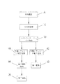
図2及び図4を参照する。図は、本考案のエリア分け充電及びエリア直列放電を行うポータブル型電源1の充電状態を示したブロック図である。入力インターフェイス部品70の入力連結部71と外部電源Aが連結された時、外部電源Aの電力を受けて各第二開閉部品60が同時に起動する。この時、各第一開閉部品30が閉止状態であることにより、各第二開閉部品60と各充電レギュレータ電子回路40と各第一電池10或いは各第二電池20とが、それぞれ独立回路を形成する。また、もう一つの充電レギュレータ電子回路40と第一電池10とが、独立回路を形成する。外部電源Aの電力は、それぞれ各充電レギュレータ電子回路40を経由して第一電池10及び第二電池20に伝送されて、独立して充電を行う。
Please refer to FIG. 2 and FIG. FIG. 1 is a block diagram showing a charging state of a
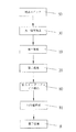
図3及び図5を参照する。図は、本考案のエリア分け充電及びエリア直列放電を行うポータブル型電源1の放電状態を示したブロック図である。出力インターフェイス部品80の出力連結部81と電子装置Bが接続され、使用者が電源スイッチ50を起動させた時、本考案のエリア分け充電及びエリア直列放電を行うポータブル型電源1内部における各第一開閉部品30が同時に起動することにより、各第一電池10と各第二電池20の間の回路が連通する。この時、各第二開閉部品60は、閉止状態であり、直列放電の形態を形成する。以上により、電力を出力供給して電子装置Bを充電する。
Please refer to FIG. 3 and FIG. FIG. 1 is a block diagram illustrating a discharge state of the
Vb1、Vb2、…Vbnは、各電池の電圧である。 Vb1, Vb2,... Vbn are voltages of the respective batteries.
直列放電Vo=システム出力電圧=各電池電圧総計=Vb1+Vb2+Vb3+…Vbn、である。 Series discharge Vo = system output voltage = total battery voltage = Vb1 + Vb2 + Vb3 +... Vbn.
従来の充電電圧要求は、Vc>Voである。 A conventional charge voltage requirement is Vc> Vo.
本考案のエリア分け充電における電圧要求は、Vc>Vb(単一電池電圧)である。 The voltage requirement in the area-based charging of the present invention is Vc> Vb (single battery voltage).
よって、本考案は、より高い効率性を有する。 Therefore, the present invention has higher efficiency.
1 エリア分け充電及びエリア直列放電を行うポータブル型電源
10 第一電池
20 第二電池
30 第一開閉部品
40 充電レギュレータ電子回路
50 電源スイッチ
60 第二開閉部品
70 入力インターフェイス部品
71 入力連結部
80 出力インターフェイス部品
81 出力連結部
A 外部電源
B 電子装置
C 共通接地点
DESCRIPTION OF
Claims (5)
前記第二電池は、前記第一電池と直列方式によって電気的に接続され、
前記第一開閉部品は、前記第一電池と前記第二電池の間に設けられ、
前記充電レギュレータ電子回路は、それぞれ前記第一電池及び前記第二電池と電気的に接続され、
前記第二開閉部品は、それぞれ前記第二電池と電気的に接続されるとともに、前記第二開閉部品は選択的に開閉され、
前記入力インターフェイス部品は、その一端に少なくとも一つの入力連結部が設けられ、前記入力連結部に対する他端が前記充電レギュレータ電子回路と電気的に接続され、
前記入力連結部は、外部電源と連結され、
前記出力インターフェイス部品は、その一端に少なくとも一つの出力連結部が設けられ、前記出力連結部に対する他端が前記第一電池及び前記第二電池と電気的に接続され、
前記出力連結部は、外部電子装置と連結されることを特徴とする、エリア分け充電及びエリア直列放電を行うポータブル型電源。 At least one first battery, at least one second battery, at least one first opening / closing component, a plurality of charge regulator electronic circuits, at least one second opening / closing component, and at least one input interface component; A portable power source that performs area-based charging and area series discharging, comprising at least one output interface component,
The second battery is electrically connected in series with the first battery,
The first opening / closing component is provided between the first battery and the second battery,
The charge regulator electronics are electrically connected to the first battery and the second battery, respectively;
The second opening / closing component is electrically connected to the second battery, respectively, and the second opening / closing component is selectively opened and closed,
The input interface component is provided with at least one input coupling portion at one end thereof, and the other end with respect to the input coupling portion is electrically connected to the charging regulator electronic circuit,
The input connection unit is connected to an external power source,
The output interface component is provided with at least one output connecting portion at one end thereof, and the other end with respect to the output connecting portion is electrically connected to the first battery and the second battery,
The portable power source for performing divided charging and area series discharging, wherein the output connecting unit is connected to an external electronic device.
前記第一開閉部品が前記電源スイッチと同時に起動することにより、前記第一電池及び前記第二電池が直列放電状態をなすことを特徴とする、請求項1に記載のエリア分け充電及びエリア直列放電を行うポータブル型電源。 The first opening / closing component is further electrically connected to a power switch,
The area-divided charging and the area series discharge according to claim 1, wherein the first battery and the second battery are in a series discharge state when the first opening / closing component is activated simultaneously with the power switch. Do portable type power supply.
前記第二開閉部品は、前記外部電源の電力によって起動し、
前記外部電源の電力は、それぞれ各前記充電レギュレータ電子回路を経由して前記第一電池及び前記第二電池に伝送されて充電することを特徴とする、請求項1に記載のエリア分け充電及びエリア直列放電を行うポータブル型電源。 The input connection part of the input interface component is connected to the external power source,
The second opening / closing component is activated by the power of the external power source,
2. The divided charging and area according to claim 1, wherein electric power of the external power source is transmitted to the first battery and the second battery via the respective charging regulator electronic circuits for charging. Portable power supply that performs series discharge.
且つ第一電池及び前記第二電池は、それぞれ複数の直列電池を有することを特徴とする、請求項1に記載のエリア分け充電及びエリア直列放電を行うポータブル型電源。 Each of the first battery and the second battery constitutes one area,
The portable power source for performing area-based charging and area series discharging according to claim 1, wherein each of the first battery and the second battery includes a plurality of series batteries.
Applications Claiming Priority (2)
| Application Number | Priority Date | Filing Date | Title |
|---|---|---|---|
| TW102202809 | 2013-02-07 | ||
| TW102202809U TWM464916U (en) | 2013-02-07 | 2013-02-07 | Partition charging and mobile power supply with series discharge in each zone |
Publications (1)
| Publication Number | Publication Date |
|---|---|
| JP3188317U true JP3188317U (en) | 2013-12-18 |
Family
ID=49781046
Family Applications (1)
| Application Number | Title | Priority Date | Filing Date |
|---|---|---|---|
| JP2013006177U Expired - Fee Related JP3188317U (en) | 2013-02-07 | 2013-10-29 | Portable power supply for area-based charging and area series discharging |
Country Status (4)
| Country | Link |
|---|---|
| US (1) | US20140217961A1 (en) |
| JP (1) | JP3188317U (en) |
| DE (1) | DE202013104820U1 (en) |
| TW (1) | TWM464916U (en) |
Families Citing this family (3)
| Publication number | Priority date | Publication date | Assignee | Title |
|---|---|---|---|---|
| TWI614964B (en) * | 2014-08-01 | 2018-02-11 | 技嘉科技股份有限公司 | Fast low voltage rechargeable battery |
| CN104967191B (en) * | 2015-07-28 | 2017-03-29 | 青岛歌尔声学科技有限公司 | For the charging circuit and portable power source of portable power source |
| DE102017010840B4 (en) * | 2017-11-23 | 2020-01-23 | Stefan Schulz | Energy supply for a prosthesis |
Family Cites Families (7)
| Publication number | Priority date | Publication date | Assignee | Title |
|---|---|---|---|---|
| JPH08329992A (en) * | 1995-05-29 | 1996-12-13 | Saitama Nippon Denki Kk | Battery pack and charger |
| US7843171B2 (en) * | 2008-01-21 | 2010-11-30 | Semtech Corporation | Method and apparatus for battery charging based on battery capacity and charging source constraints |
| US8441230B2 (en) * | 2008-09-08 | 2013-05-14 | Techtronic Power Tools Technology Limited | Battery charger |
| US8508188B2 (en) * | 2009-04-17 | 2013-08-13 | Anton/Bauer, Inc. | Universal charge module |
| CN102110997B (en) * | 2009-12-28 | 2013-07-10 | 光宝电子(广州)有限公司 | Balance method of battery pack |
| JP5711040B2 (en) * | 2011-04-28 | 2015-04-30 | トランスフォーム・ジャパン株式会社 | Bidirectional switch and charge / discharge protection device using the same |
| WO2013142964A1 (en) * | 2012-03-25 | 2013-10-03 | Sherstyuk Tymofiy | Extended life battery |
-
2013
- 2013-02-07 TW TW102202809U patent/TWM464916U/en not_active IP Right Cessation
- 2013-10-29 JP JP2013006177U patent/JP3188317U/en not_active Expired - Fee Related
- 2013-10-29 DE DE202013104820U patent/DE202013104820U1/en not_active Expired - Lifetime
- 2013-11-01 US US14/069,389 patent/US20140217961A1/en not_active Abandoned
Also Published As
| Publication number | Publication date |
|---|---|
| TWM464916U (en) | 2013-11-01 |
| US20140217961A1 (en) | 2014-08-07 |
| DE202013104820U1 (en) | 2013-11-15 |
Similar Documents
| Publication | Publication Date | Title |
|---|---|---|
| US11349317B2 (en) | Charger integrated circuit for charging battery device and electronic device including the charger integrated circuit | |
| US9444118B2 (en) | Battery pack | |
| CN103001275B (en) | Battery bag, electronic installation and battery bag arrangement | |
| US7592781B2 (en) | Charger control circuit with automatic polarity selection | |
| CN107834519A (en) | Lithium battery protection control ASIC chip system | |
| CN105896656A (en) | Bidirectional equalization circuit | |
| EP2947470A1 (en) | Battery management system | |
| GB2535396A (en) | Lithium ion storage battery and charge/discharge control method therefor | |
| CN103715744B (en) | Multifunctional portable power source | |
| TW201635669A (en) | Portable energy storage and power supply device | |
| CN107302248A (en) | A kind of electric tool | |
| JP3188317U (en) | Portable power supply for area-based charging and area series discharging | |
| CN103746423A (en) | Novel mobile power supply and preparing method thereof | |
| CN109638904A (en) | Lithium battery protection board | |
| CN203243068U (en) | Mobile power supply capable of charging in subarea and discharging in series areas | |
| CN104052091A (en) | Novel battery management architecture capable of charging in subareas and discharging in series areas | |
| KR101602877B1 (en) | Energy storage device constructed to supply electric power from individual batterycell | |
| CN214280983U (en) | Equalization chip of series battery pack and battery management system | |
| CN206117218U (en) | Mobile power supply | |
| TW201433046A (en) | New battery management architecture for zone charging and series discharge in each zone | |
| CN103746424A (en) | Application of lithium iron phosphate battery in mobile power supply | |
| JP2022530388A (en) | Pre-charge circuit and battery system including it | |
| KR101640137B1 (en) | Contact holding circuit for the electrical connector | |
| CN108155694A (en) | Laptop electric power and charging method | |
| CN203026979U (en) | Charging power supplying circuit and charging power supplying device |
Legal Events
| Date | Code | Title | Description |
|---|---|---|---|
| R150 | Certificate of patent or registration of utility model |
Ref document number: 3188317 Country of ref document: JP Free format text: JAPANESE INTERMEDIATE CODE: R150 Free format text: JAPANESE INTERMEDIATE CODE: R150 |
|
| R250 | Receipt of annual fees |
Free format text: JAPANESE INTERMEDIATE CODE: R250 |
|
| R250 | Receipt of annual fees |
Free format text: JAPANESE INTERMEDIATE CODE: R250 |
|
| LAPS | Cancellation because of no payment of annual fees |