JP3178043U - Stove with piezoelectric ignition mechanism - Google Patents
Stove with piezoelectric ignition mechanism Download PDFInfo
- Publication number
- JP3178043U JP3178043U JP2012003614U JP2012003614U JP3178043U JP 3178043 U JP3178043 U JP 3178043U JP 2012003614 U JP2012003614 U JP 2012003614U JP 2012003614 U JP2012003614 U JP 2012003614U JP 3178043 U JP3178043 U JP 3178043U
- Authority
- JP
- Japan
- Prior art keywords
- burner
- spark plug
- stove
- gas supply
- ignition
- Prior art date
- Legal status (The legal status is an assumption and is not a legal conclusion. Google has not performed a legal analysis and makes no representation as to the accuracy of the status listed.)
- Expired - Fee Related
Links
Images


Abstract
【課題】点火プラグとバーナーの火口との間隔を一定に保ち、点火不良のおそれのない圧電点火機構を備えたコンロを提供する。
【解決方法】コンロ内に延伸させて設けられたバーナー4のガス供給部側の端部近傍上面に、圧電点火機構の点火プラグ2を装着する点火プラグ装着板が溶接等で固着されてなり、点火プラグ2とバーナー4の火口との位置関係を固定することにより、安定、確実な点火を可能にし、かつ、コンロの燃焼室とガス供給部とを隔離する隔離板11に、点火プラグ装着板を介して点火プラグ2が固着されたバーナー4を挿入する下部が円弧の凸字形状の開口が穿って円筒形バーナーの軸回りの回転を抑制して燃焼室内の火力分布を安定に保持してなる圧電点火機構を備えたコンロ1による。
【選択図】図1A stove provided with a piezoelectric ignition mechanism that maintains a constant distance between a spark plug and a crater of a burner and does not cause a risk of ignition failure.
A spark plug mounting plate for mounting a spark plug 2 of a piezoelectric ignition mechanism is fixed by welding or the like on an upper surface in the vicinity of an end portion on the gas supply side of a burner 4 provided extending in a stove. By fixing the positional relationship between the spark plug 2 and the crater of the burner 4, stable and reliable ignition is possible, and the spark plug mounting plate is provided on the separator plate 11 that separates the combustion chamber of the stove and the gas supply unit. The lower part into which the burner 4 to which the spark plug 2 is fixed is inserted through a circular arc-shaped convex opening, and the rotation of the cylindrical burner around the axis is suppressed to stably maintain the thermal power distribution in the combustion chamber. By the stove 1 provided with the piezoelectric ignition mechanism which becomes.
[Selection] Figure 1
Description
左右いずれか一方の側面にカセットボンベを装着するガス供給部を備え、他の三方(前面、背面ともう一方の側面)は燃焼に必要な空気の流入孔が複数設けられた金属製の側板で構成され、内部にガス供給部からのガスを燃焼させるバーナーを前面と背面との間の中央部に延伸させて設けられたコンロにおいて、安定、確実に点火できる圧電点火機構を備えたコンロに関する。 It has a gas supply part that mounts a cassette cylinder on either the left or right side, and the other three sides (front, back, and other side) are metal side plates that are provided with multiple air inflow holes necessary for combustion. The present invention relates to a stove including a piezoelectric ignition mechanism that is configured and provided with a burner that burns gas from a gas supply unit extending in a central portion between a front surface and a back surface and that can stably and surely ignite.
従来の、燃焼室内にガス供給部からのガスを燃焼させるバーナーを前面と背面との間の中央部に延伸させて設けられたコンロ(特許文献1)においては、図5に示すように、圧電点火機構の点火プラグ2は、燃焼室とガス供給部との隔離板11のバーナー4が取り付けられた位置の上方に、点火プラグ装着板3’を介してネジ止めされ、その先端に設けられた放電電極2aがバーナー4の火口4a近くに配置された構造になっていた。このため、製造に当たっては、前記隔離板11への点火プラグ装着板3の取り付け位置をはじめとして点火プラグとバーナーの火口との間隔等についてきめ細かな調整が必要となり、また長期使用によって点火プラグ装着板の姿勢が、取付けネジの緩みになどによって不安定になると、前記点火プラグの放電対象位置も不安定に変化し、点火プラグのスパークがバーナーの火口に届かず点火不良となるおそれがあった。
また、円筒形のバーナーにあっては、固定したネジの緩み等によって回転して火口がいずれか一方に偏り、燃焼室内の火力分布に不均衡を生じるおそれもあった。
In a conventional stove (Patent Document 1) in which a burner for burning gas from a gas supply unit in a combustion chamber is extended to the center between the front surface and the back surface, as shown in FIG. The
Further, in the case of a cylindrical burner, the crater is biased to one of them due to loosening of a fixed screw or the like, and there is a possibility that the thermal power distribution in the combustion chamber is unbalanced.
本考案は上記背景技術に鑑みてなされたもので、点火プラグとバーナーの火口との間隔を一定に保ち、点火不良のおそれのない圧電点火機構を備えたコンロを提供するものである。 The present invention has been made in view of the above-described background art, and provides a stove provided with a piezoelectric ignition mechanism that maintains a constant distance between a spark plug and a crater of a burner and does not cause ignition failure.
本考案者は上記課題を下記の手段により解決した。
(1)左右いずれか一方の側面にカセットボンベを装着するガス供給部を備え、他の三方(前面、背面ともう一方の側面)は燃焼に必要な空気の流入孔が複数設けられた金属製の側板で構成され、内部にガス供給部からのガスを燃焼させるバーナーを前面と背面との間の中央部に延伸させて設けられたコンロにおいて、
前記コンロ内に延伸させて設けられたバーナーのガス供給部側の端部近傍上面に、圧電点火機構の点火プラグを装着する点火プラグ装着板が固着されてなり、点火プラグとバーナーの火口との位置関係を固定することにより、安定、確実な点火を可能にしてなることを特徴とする圧電点火機構を備えたコンロ。
(2)点火プラグ装着板は、前記バーナー上に一定間隔を置いて配置される中央の点火プラグ装着部と、バーナーの上部外形に合わせて加工された左右両端部のバーナー固着部と、前記バーナー固着部の両脇に突出されたウイングとが一体に形成されてなり、前記点火プラグ装着部上に前記点火プラグが載置、固定されてなることを特徴とする前項(1)に記載の圧電点火機構を備えたコンロ。
(3)点火プラグ装着板のバーナーへの固着が、溶接によって行われることを特徴とする前項(1)又は(2)に記載の圧電点火機構を備えたコンロ。
(4)コンロの燃焼室とガス供給部とを隔離する隔離板に、点火プラグ装着板を介して点火プラグが固着されたバーナーを挿入する下部が円弧の凸字形状の開口が穿たれてなることを特徴とする前項(1)〜(3)のいずれか1項に記載の圧電点火機構を備えたコンロ。
The inventor has solved the above problems by the following means.
(1) A gas supply unit that mounts a cassette cylinder on either the left or right side, and the other three sides (front, back, and other side) are made of metal with multiple air inflow holes required for combustion In a stove provided with a burner configured to extend in the center between the front and back, a burner configured to burn the gas from the gas supply unit inside
A spark plug mounting plate for mounting a spark plug of the piezoelectric ignition mechanism is fixed to an upper surface in the vicinity of an end portion on the gas supply side of the burner provided to extend in the stove, and the spark plug and the crater of the burner are connected to each other. A stove equipped with a piezoelectric ignition mechanism characterized by enabling stable and reliable ignition by fixing the positional relationship.
(2) The spark plug mounting plate includes a center spark plug mounting portion disposed at a predetermined interval on the burner, burner fixing portions at both left and right ends processed according to the upper outer shape of the burner, and the burner The piezoelectric as described in (1) above, wherein wings protruding on both sides of the fixing portion are integrally formed, and the spark plug is placed and fixed on the spark plug mounting portion. A stove with an ignition mechanism.
(3) A stove provided with the piezoelectric ignition mechanism as described in (1) or (2) above, wherein the ignition plug mounting plate is fixed to the burner by welding.
(4) The lower part into which the burner to which the ignition plug is fixed via the ignition plug mounting plate is inserted into the separator plate that separates the combustion chamber of the stove from the gas supply part is formed with a convex opening having a circular arc shape. A stove comprising the piezoelectric ignition mechanism according to any one of (1) to (3) above.
本考案の圧電点火機構を備えたコンロにより、下記の効果が発揮できる。
〈1〉左右いずれか一方の側面にカセットボンベを装着するガス供給部を備え、他の三方(前面、背面ともう一方の側面)は燃焼に必要な空気の流入孔が複数設けられた金属製の側板で構成され、内部にガス供給部からのガスを燃焼させるバーナーを前面と背面との間の中央部に延伸させて設けられたコンロにおいて、
前記コンロ内に延伸させて設けられたバーナーのガス供給部側の端部近傍上面に、圧電点火機構の点火プラグを装着する点火プラグ装着板が固着されているので、この点火プラグ装着板に点火プラグを装着することによって点火プラグとバーナーの火口との位置関係が固定され、安定、確実な点火が可能になる。
また、従来のコンロの製造時に行われていた点火プラグ装着板の隔離板への取付けをはじめとして点火プラグとバーナーの火口との間隔調整等細心の注意を要した作業がなくなり、生産性が向上し、量産による低廉化を図ることができる。
〈2〉点火プラグ装着板は、前記バーナー上に一定間隔を置いて配置される中央の点火プラグ装着部と、バーナーの上部外形に合わせて加工された左右両端部のバーナー固着部と、前記バーナー固着部の両脇に突出されたウイングとが一体に形成されてなるので、左右両端部のバーナー固着部をバーナーに溶接等によって固着した後前記点火プラグを点火プラグ装着部に載置してネジ止め等によって固定すればよく、作業効率の向上に資する。
〈3〉コンロの燃焼室とガス供給部とを隔離する隔離板に、点火プラグ装着板を介して点火プラグが固着されたバーナーを挿入する下部が円弧の凸字形状の開口が穿たれているので、前記バーナーを前記開口に挿入したとき前記ウイングと前記点火プラグ装着部とを連結する垂直面部が前記隔離板に当接し、かつ前記ウイングの上面が前記開口の中央部に水平に形成され部分に当接してバーナーの軸回りの回転を抑止でき、燃焼室内の火力分布を常に一定に保つことができる。
The stove equipped with the piezoelectric ignition mechanism of the present invention can exhibit the following effects.
<1> A metal supply unit equipped with a gas supply unit that mounts a cassette cylinder on either the left or right side, and the other three sides (front, back, and other side) are made of metal with multiple air inlets required for combustion In a stove provided with a burner configured to extend in the center between the front and back, a burner configured to burn the gas from the gas supply unit inside
A spark plug mounting plate for mounting a spark plug of the piezoelectric ignition mechanism is fixed to the upper surface near the end of the burner provided on the gas supply side of the burner. By attaching the plug, the positional relationship between the spark plug and the crater of the burner is fixed, and stable and reliable ignition is possible.
Also, productivity has been improved by eliminating the need for meticulous work such as adjusting the distance between the spark plug and the burner crater, such as attaching the spark plug mounting plate to the separator plate, which was done when manufacturing a conventional stove. In addition, the cost can be reduced by mass production.
<2> The spark plug mounting plate includes a central spark plug mounting portion disposed at a predetermined interval on the burner, burner fixing portions at both left and right ends processed according to the upper outer shape of the burner, and the burner Since the wings protruding on both sides of the fixing part are integrally formed, after fixing the burner fixing parts at the left and right ends to the burner by welding or the like, the spark plug is placed on the spark plug mounting part and screwed. It only needs to be fixed with a stop, etc., which contributes to improved work efficiency.
<3> An opening having a convex arc shape is formed in the lower part into which the burner to which the spark plug is fixed via the spark plug mounting plate is inserted into the separator that separates the combustion chamber of the stove and the gas supply unit. Therefore, when the burner is inserted into the opening, a vertical surface portion connecting the wing and the spark plug mounting portion abuts on the separator, and a top surface of the wing is formed horizontally at a central portion of the opening. The rotation around the axis of the burner can be suppressed by abutting on the nozzle, and the thermal power distribution in the combustion chamber can always be kept constant.
本考案のコンロを実施するための形態を、実施例の図に基づいて説明する。
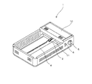
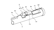
図1は本考案の圧電点火機能を備えたコンロの一実施例の斜視図、図2は点火プラグ装着板がバーナーに固着された状態の斜視図、図3はバーナーに固着された点火プラグ装着板に点火プラグが載置固定された状態の斜視図であり、図4本考案の点火プラグが載置固定されたバーナーの取付け方法の説明用斜視図である。
図において1はコンロ、2は点火プラグ、2aは放電電極、2bは絶縁碍子、2cは止め金、3は点火プラグ装着板、3aは点火プラグ装着部、3bはバーナーへの固着部、3cはウイング、3dは垂直面部、3eはねじ穴、3fはスリット、4はバーナー、4aは火口、5はガス点火・供給量調節つまみ、6は安全レバー、10はガス供給部、11は隔離板を示す。
EMBODIMENT OF THE INVENTION The form for implementing the stove of this invention is demonstrated based on the figure of an Example.
1 is a perspective view of an embodiment of a stove having a piezoelectric ignition function according to the present invention, FIG. 2 is a perspective view of a state in which a spark plug mounting plate is fixed to a burner, and FIG. 3 is a spark plug mounted to the burner. 4 is a perspective view of a state in which a spark plug is placed and fixed on a plate, and FIG. 4 is a perspective view for explaining a method of mounting a burner on which the spark plug of the present invention is placed and fixed.
In the figure, 1 is a stove, 2 is a spark plug, 2a is a discharge electrode, 2b is an insulator, 2c is a stopper, 3 is a spark plug mounting plate, 3a is a spark plug mounting portion, 3b is a fixing portion to the burner, 3c is Wing, 3d is a vertical surface portion, 3e is a screw hole, 3f is a slit, 4 is a burner, 4a is a crater, 5 is a gas ignition / supply amount adjustment knob, 6 is a safety lever, 10 is a gas supply portion, and 11 is a separator Show.
本考案の圧電点火機構を備えたコンロ1は、図1に示すような左右いずれか一方の側面にカセットボンベを装着するガス供給部10を備え、他の三方(前面、背面ともう一方の側面)は燃焼に必要な空気の流入孔が複数設けられた金属製の側板で構成され、内部にガス供給部からのガスを燃焼させるバーナー4を前面と背面との間の中央部に延伸させて設けられてなり、かつ、図2に示すように、圧電点火機構の点火プラグ2を載置、固定する点火プラグ装着板3が、前記コンロ1内に延伸させて設けられたバーナー4のガス供給部10側の端部近傍上面に溶接等で固着して形成されてなるものである。
The stove 1 equipped with the piezoelectric ignition mechanism of the present invention includes a
前記点火プラグ装着板3は、図2に示すように、前記バーナー4上に一定間隔を置いて配置される中央の点火プラグ装着部3aと、バーナー4の上部外形に合わせて加工された左右両端部のバーナー固着部3bと、前記バーナー固着部3bの前後に突出させて設けられたウイング3cとが一体として形成されており、前記点火プラグ装着部3aには、前記点火プラグ2を装着する止め金2c(図3参照)用の垂直面部3d及びねじ穴3eが設けられている。
As shown in FIG. 2, the spark
前記点火プラグ2は、絶縁碍子2bから突出した放電電極2aから金属製のバーナー4への放電によって火口4aから放出されるガスに点火するものであって、図3に示すように絶縁碍子2b中央部に設けたくびれに前記止め金2cを渡してねじ止めによって点火プラグ装着部3aに固定される。
そして、放電電極2aと一体に構成された導体が前記絶縁碍子2b内を貫通して絶縁碍子2bの他端から突出した端子に被覆電線2dが接続され、該被覆電線2dは前記ガス供給部10内に設けられた圧電素子(図示せず)に接続され、ガス供給部10の前面パネルに設けられたガス点火・供給量調節つまみ5の操作によって前記圧電素子の起電力が点火プラグ2の放電電極2aに伝達されることによってバーナー4の点火が実行される。
The
Then, a covered
本考案の点火プラグ装着板3を介して点火プラグ2が固着されたバーナー4のコンロ本体への取り付けは、図4に示すように、前記ガス供給部10とコンロの燃焼室を隔離すると隔離板11に下部が円弧の凸字形状の開口12を穿ち、前記バーナーを前記開口12に挿入することによって行われる。
挿入によって前記ウイング3cと前記点火プラグ装着部3aとを連結する垂直面部3dが前記隔離板11に当接し、かつ前記ウイング3cの上面が前記開口12の中央部に水平に形成された部分に当接してバーナー4の軸回りの回転を抑止し、燃焼室内の火力分布を常に一定に保つよう作用する。
As shown in FIG. 4, the
A
図1において、バーナー4を直線状に延伸されたものとして示したが、特許文献1に記載されたバーナー4のように緩やかに蛇行したS字形状でなるものであってもよい。
また、前記バーナー4の上に一定間隔を置いて着脱自在に装着され、炭またはセラミック端を載置して前記バーナー4の炎によって着火、若しくは加熱されるよう構成された炭受け(図示せず)を備えたコンロであってよく、この場合には点火プラグ2が存在する近傍上の前記炭受けに、炭受けへの放電を抑止するとともに、炭受けを装着した状態でも点火プラグの点検保守ができるような開口部を設けておくことが好ましい。
In FIG. 1, the
Further, a charcoal tray (not shown) is detachably mounted on the
1:コンロ
2:点火プラグ
2a:放電電極
2b:絶縁碍子
2c:止め金
2d:被覆電線
3:点火プラグ装着板
3a:点火プラグ装着部
3b:バーナーへの固着部
3c:ウイング
3d:垂直面部
3e:ねじ穴
3f:スリット
3’:従来の点火プラグ装着板
4:バーナー
4a:火口
5:ガス点火・供給量調節つまみ
6:安全レバー
10:ガス供給部
11:隔離板
12:下部が円弧の凸字形状の開口
1: Stove 2: Spark
Claims (4)
前記コンロ内に延伸させて設けられたバーナー(4)のガス供給部(10)側の端部近傍上面に、圧電点火機構の点火プラグ(2)を装着する点火プラグ装着板(3)が固着されてなり、点火プラグ(2)とバーナー(4)の火口(4a)との位置関係を固定することにより、安定、確実な点火を可能にしてなることを特徴とする圧電点火機構を備えたコンロ。 A metal supply with a gas supply (10) for mounting a cassette cylinder on either the left or right side, and the other three sides (front, back and other side) are made of metal with multiple air inflow holes required for combustion In a stove provided with a burner (4) that extends in the center between the front surface and the back surface, the burner (4) that combusts the gas from the gas supply section (10) inside,
An ignition plug mounting plate (3) for mounting the ignition plug (2) of the piezoelectric ignition mechanism is fixed to the upper surface in the vicinity of the end of the burner (4) on the gas supply unit (10) side provided in the stove. The piezoelectric ignition mechanism is characterized in that stable and reliable ignition is possible by fixing the positional relationship between the spark plug (2) and the crater (4a) of the burner (4). Stove.
A lower part for inserting a burner (4) having a spark plug (2) fixed thereto through a spark plug mounting plate (3) to a separator plate (11) separating the combustion chamber of the stove and the gas supply part (10). The stove provided with the piezoelectric ignition mechanism according to any one of claims 1 to 3, wherein an arcuate convex opening (12) is formed.
Priority Applications (2)
| Application Number | Priority Date | Filing Date | Title |
|---|---|---|---|
| JP2012003614U JP3178043U (en) | 2012-06-15 | 2012-06-15 | Stove with piezoelectric ignition mechanism |
| PCT/IB2012/001870 WO2013080000A1 (en) | 2011-12-01 | 2012-09-26 | Smokeless charcoal roaster |
Applications Claiming Priority (1)
| Application Number | Priority Date | Filing Date | Title |
|---|---|---|---|
| JP2012003614U JP3178043U (en) | 2012-06-15 | 2012-06-15 | Stove with piezoelectric ignition mechanism |
Publications (1)
| Publication Number | Publication Date |
|---|---|
| JP3178043U true JP3178043U (en) | 2012-08-30 |
Family
ID=48004816
Family Applications (1)
| Application Number | Title | Priority Date | Filing Date |
|---|---|---|---|
| JP2012003614U Expired - Fee Related JP3178043U (en) | 2011-12-01 | 2012-06-15 | Stove with piezoelectric ignition mechanism |
Country Status (1)
| Country | Link |
|---|---|
| JP (1) | JP3178043U (en) |
Cited By (2)
| Publication number | Priority date | Publication date | Assignee | Title |
|---|---|---|---|---|
| JP2015105770A (en) * | 2013-11-29 | 2015-06-08 | 株式会社 エコグリル | Ignition mechanism of gas cooking stove |
| US20160209027A1 (en) * | 2015-01-16 | 2016-07-21 | Lg Electronics Inc. | Cooking device |
-
2012
- 2012-06-15 JP JP2012003614U patent/JP3178043U/en not_active Expired - Fee Related
Cited By (4)
| Publication number | Priority date | Publication date | Assignee | Title |
|---|---|---|---|---|
| JP2015105770A (en) * | 2013-11-29 | 2015-06-08 | 株式会社 エコグリル | Ignition mechanism of gas cooking stove |
| US20160209027A1 (en) * | 2015-01-16 | 2016-07-21 | Lg Electronics Inc. | Cooking device |
| US10222058B2 (en) * | 2015-01-16 | 2019-03-05 | Lg Electronics Inc. | Cooking device |
| US10982845B2 (en) | 2015-01-16 | 2021-04-20 | Lg Electronics Inc. | Cooking device |
Similar Documents
| Publication | Publication Date | Title |
|---|---|---|
| US8890396B2 (en) | Spark plug for a gas-operated internal combustion engine | |
| US5468145A (en) | Sealed gas burner assembly | |
| JP3178043U (en) | Stove with piezoelectric ignition mechanism | |
| RU90532U1 (en) | TORCH INSTALLATION | |
| CN202660747U (en) | Combustor device | |
| WO2021093554A1 (en) | Heating device and smokeless electronic cigarette | |
| WO2012088731A1 (en) | Bow-shape multi-spot firing spark plug with lateral electrode | |
| JP3178044U (en) | Anthracite fireware | |
| CN213513980U (en) | Ignition device and combustion device | |
| CN215016330U (en) | Barbecue oven and side oven ignition needle thereof | |
| CN212108497U (en) | Ignition device for boiler burner | |
| CN110021880A (en) | Spark plug | |
| US8985078B2 (en) | Combustion chamber structure by using preheating net and spark plug to ignite | |
| US1841023A (en) | Nonexplosive burner assembly for oil burners | |
| CN103712245B (en) | Gas utensil igniter and application thereof | |
| JP6183050B2 (en) | Discharge igniter for oil combustor | |
| KR200380477Y1 (en) | Nozzle burner for gas range | |
| CN219422651U (en) | Infrared gas oven | |
| JP3597587B2 (en) | Ignition device | |
| JP7468217B2 (en) | Spark plug | |
| JP2835578B2 (en) | Gas burner | |
| CN211502896U (en) | Gas stove | |
| JPH037725Y2 (en) | ||
| CN207009894U (en) | A kind of discharge tube | |
| KR0116470Y1 (en) | Ignition plug for gas-boiler |
Legal Events
| Date | Code | Title | Description |
|---|---|---|---|
| R150 | Certificate of patent or registration of utility model |
Free format text: JAPANESE INTERMEDIATE CODE: R150 |
|
| FPAY | Renewal fee payment (event date is renewal date of database) |
Free format text: PAYMENT UNTIL: 20150808 Year of fee payment: 3 |
|
| R250 | Receipt of annual fees |
Free format text: JAPANESE INTERMEDIATE CODE: R250 |
|
| R250 | Receipt of annual fees |
Free format text: JAPANESE INTERMEDIATE CODE: R250 |
|
| LAPS | Cancellation because of no payment of annual fees |