JP3176456U - Expandable mobile power supply - Google Patents
Expandable mobile power supply Download PDFInfo
- Publication number
- JP3176456U JP3176456U JP2012002094U JP2012002094U JP3176456U JP 3176456 U JP3176456 U JP 3176456U JP 2012002094 U JP2012002094 U JP 2012002094U JP 2012002094 U JP2012002094 U JP 2012002094U JP 3176456 U JP3176456 U JP 3176456U
- Authority
- JP
- Japan
- Prior art keywords
- control module
- connection port
- power
- power supply
- battery unit
- Prior art date
- Legal status (The legal status is an assumption and is not a legal conclusion. Google has not performed a legal analysis and makes no representation as to the accuracy of the status listed.)
- Expired - Lifetime
Links
Images


Landscapes
- Charge And Discharge Circuits For Batteries Or The Like (AREA)
- Secondary Cells (AREA)
Abstract
【課題】必要に応じてバッテリー容量を増減可能な拡充式モバイル電源装置を提供する。
【解決手段】電源制御モジュール1及びバッテリーユニット2、3、4、5から構成し、電源制御モジュールには、充電制御回路などを収容すると共に、スイッチボタン124、作動状態インジケーターユニット125、第一接続ポートを備える。また、バッテリーユニットは、バッテリーを収容して前記電源制御モジュールの第一接続ポートに接続する第二接続ポート25、さらに重ね合わされる他のバッテリーユニットの第二接続ポートに接続する第三接続ポート26を備え、電源制御モジュールをバッテリーユニットに重ね合わせて結合する。さらに、その第一接続ポート126をバッテリーユニットの第二接続ポート25に接続し、さらに他のバッテリーユニットを同様にして重ね合わせて結合する。
【選択図】図5An expandable mobile power supply apparatus capable of increasing or decreasing a battery capacity as required.
The power supply control module includes a power supply control module and battery units. The power supply control module accommodates a charging control circuit, a switch button, an operation state indicator unit, and a first connection. Provide a port. In addition, the battery unit accommodates a battery and connects the second connection port 25 connected to the first connection port of the power supply control module, and further the third connection port 26 connected to the second connection port of another battery unit to be overlaid. The power supply control module is overlapped and coupled to the battery unit. Further, the first connection port 126 is connected to the second connection port 25 of the battery unit, and other battery units are overlapped and coupled in the same manner.
[Selection] Figure 5
Description
本考案は、拡充式モバイル電源装置に関し、特にバックアップ及び充/放電に便利な携帯装置で、使用ニーズに基づき、総バッテリー容量を増加或いは減少させることができ、伝送ポートを通して、ポータブルデジタル機器に、充電或いは給電可能な拡充式モバイル電源装置に関する。 The present invention relates to an expandable mobile power supply device, particularly a portable device that is convenient for backup and charge / discharge, and can increase or decrease the total battery capacity based on usage needs. The present invention relates to an expandable mobile power supply device that can be charged or powered.
携帯電話端末、ノート型コンピューター、デジタルカメラ、音楽プレーヤー等のポータブルデジタル機器はどれも、充/放電バッテリーを用いて、使用時の電源としている。 Portable digital devices such as mobile phone terminals, notebook computers, digital cameras, and music players all use a charge / discharge battery as a power source during use.
一般に、ポータブルデジタル機器に使用するバッテリーに対して充電を行う時には、配備する充電器を通して、商用交流電源を一定の電圧レベルに転換して行う。
しかし、商用交流電源を得ることができない環境下では、充電上の困難を招き、或いは該ポータブル機器の使用を中断しなければならないという状況が発生する。
Generally, when charging a battery used in a portable digital device, a commercial AC power source is converted to a constant voltage level through a charger that is provided.
However, in an environment where a commercial AC power supply cannot be obtained, a situation in which charging becomes difficult or use of the portable device must be interrupted occurs.
よって、随時携帯可能な充電装置が市販されている。
該ポータブル電源装置により、使用者は商用交流電源がない環境においても、ポータブルデジタル機器に対して充電或いは給電することができる。
Therefore, charging devices that are portable at any time are commercially available.
The portable power supply device allows the user to charge or supply power to the portable digital device even in an environment where there is no commercial AC power supply.
従来のポータブル電源装置は、充電バッテリー及び制御回路からなり、ケーシング中に一緒に収納される。
それらは、総バッテリー容量の大きさに応じて、製品として分類される。
容量が小さいポータブル電源装置製品は、軽量でコンパクトという長所を備えるが、使用時間が短いという欠点が存在する。
大容量のポータブル電源装置製品は、大きくて重く、携帯に不便であり、しかも充電バッテリーには、使用年限及び回数の制限があるため、ポータブル電源装置の性能が低下、或いは損壊した時には、全体を廃棄せざるを得ない。
本考案は従来のポータブル電源装置の上記した欠点に鑑みてなされたものである。
A conventional portable power supply device consists of a rechargeable battery and a control circuit and is housed together in a casing.
They are classified as products according to the size of the total battery capacity.
Portable power supply products with a small capacity have the advantage of being lightweight and compact, but have the disadvantage of short usage time.
Large-capacity portable power supply products are large, heavy, and inconvenient to carry, and the rechargeable battery has a limited use age and number of times. It must be discarded.
The present invention has been made in view of the above-mentioned drawbacks of conventional portable power supply devices.
本考案が解決しようとする課題は、使用者のバッテリー容量に対するニーズに基づき、バッテリーユニットを結合する方法で、総バッテリー容量を必要に応じて増加或いは減少させることができ、また携帯時の体積及び重量を調整でき、必要時には、バッテリーユニットを新しくするだけで、ポータブル電源装置の性能を上げることができ、資源の浪費を減らせる拡充式モバイル電源装置を提供することである。 The problem to be solved by the present invention is that a battery unit is combined based on the user's needs for battery capacity, and the total battery capacity can be increased or decreased as necessary. To provide an expandable mobile power supply apparatus that can adjust the weight and, when necessary, improve the performance of the portable power supply apparatus by simply renewing the battery unit, and reduce waste of resources.
上記課題を解決するため、本考案は下記の拡充式モバイル電源装置を提供する。
拡充式モバイル電源装置は、電源制御モジュール及び1個或いは1個以上のバッテリーユニットからなり、バッテリー容量拡大の目的を達成し、
該電源制御モジュール内には、回路制御板、作動状態インジケーターユニット、第一接続ポート、電源入力ポート、電源出力ポートを備え、
単一のバッテリーユニット内には、コントローラー、バッテリー、第二接続ポート及び第三接続ポートを備え、
該制御モジュールを、該バッテリーユニットと連結し通電させると、該制御モジュールの電源入力ポートにより、該バッテリーユニットに充電され、バックアップ電力が蓄えられ、
必要に応じて、該制御モジュールの電源出力ポートにより電力を出力し、電力を必要とするポータブルデジタル機器に給電し、
該制御モジュールは、1個或いは数個のバッテリーユニットに充電でき、充電完了後は、取り付け及び取り外しが容易で、これにより1個或いは数個のバッテリーユニットを選択して使用できる。
バッテリーには循環寿命の問題があるが、単一のバッテリーユニットに損壊が発生した場合でも全体を交換する必要はなく、損壊したバッテリーユニットを取り外して補充、或いは交換するだけでよいため、購入コストを大幅に引き下げられ、また環境に配慮した使用形態とすることができる。
In order to solve the above problems, the present invention provides the following expandable mobile power supply device.
The expandable mobile power supply unit consists of a power control module and one or more battery units, and achieves the purpose of expanding battery capacity.
The power control module includes a circuit control board, an operation state indicator unit, a first connection port, a power input port, and a power output port.
A single battery unit includes a controller, a battery, a second connection port, and a third connection port.
When the control module is connected to the battery unit and energized, the battery unit is charged by the power input port of the control module, and backup power is stored.
If necessary, output power from the power output port of the control module to supply power to portable digital devices that require power,
The control module can charge one or several battery units, and can be easily attached and detached after the charging is completed, so that one or several battery units can be selected and used.
Although there is a problem with the circulation life of the battery, even if a single battery unit is damaged, it is not necessary to replace the entire battery unit, and it is only necessary to remove and replace or replace the damaged battery unit. Can be drastically reduced and can be used in consideration of the environment.
本考案の拡充式モバイル電源装置は、使用者のバッテリー容量に対するニーズに基づき、バッテリーユニットを結合する方法で、総バッテリー容量をフレキシブルに増加或いは減少させることができ、また携帯時の体積及び重量を調整でき、必要時には、バッテリーユニットを新しくするだけで、ポータブル電源装置の性能を上げることができ、資源の浪費を減らすことができる。 The expandable mobile power device of the present invention can flexibly increase or decrease the total battery capacity by combining battery units based on the user's battery capacity needs. It can be adjusted, and when necessary, simply renewing the battery unit can improve the performance of the portable power supply and reduce waste of resources.
以下に図面を参照しながら本考案を実施するための最良の形態について詳細に説明する。 The best mode for carrying out the present invention will be described below in detail with reference to the drawings.
図1、2、3に示すように、本考案拡充式モバイル電源装置は、電源制御モジュール1、及び1個或いは1個以上の単一のバッテリーユニット2、3、4、5からなる。
As shown in FIGS. 1, 2, and 3, the expandable mobile power supply device of the present invention includes a power
図2に示すように、電源制御モジュール1の殼体11内には、回路板12を設置する。
As shown in FIG. 2, a
該回路板12上には、充電制御回路121、電源昇/降圧転換回路122、電源管理回路123、スイッチボタン124、作動状態インジケーターユニット125、バッテリーユニットに接続する第一接続ポート126、電源入力ポート127、電源出力ポート128を設置する。
On the
該殼体11のバッテリーユニットに相対する面には、定位孔13及び係合孔14を設置する。
A
該電源制御モジュール1の電源入力ポート127と充電制御回路121とは電気的に接続し、充電制御回路121、昇/降圧転換回路122、電源管理回路123間は、回路接続を構成する。
The
電源管理回路123とスイッチボタン124及び作動状態インジケーターユニット125とは電気的接続を構成し、電源昇/降圧転換回路122と電源出力ポート128、第一接続ポート126とは電気的接続を構成する。
The
該回路板12のスイッチボタン124、作動状態インジケーターユニット125、第一接続ポート126及び電源入力ポート127、電源出力ポート128は、該電源制御モジュール1の殼体11外に露出し、これにより使用者は外部から接続し、押釦操作し、或いは目視することができる。
The
該電源入力ポート127には、アダプター(Adapter)端子を接続して直流電源を、該電源制御モジュール1中の電源出力ポート128に入力し、充電或いは給電が必要なポータブルデジタル機器の給電端と接続し、充電或いは給電を行う。
An adapter (Adapter) terminal is connected to the
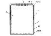
図1に示すように、該単一のバッテリーユニット2、3、4、5の上記電源制御モジュールに相対する殼体21上には、電源制御モジュール、又は他のバッテリーユニットの下半部をスライドして収容する収容設置空間22を設置する。
As shown in FIG. 1, the lower half of the power control module or other battery unit is slid on the
該単一のバッテリーユニット2には、コントローラー23、バッテリー24、電源制御モジュールの上記第一接続ポート又は他のバッテリーユニットの第三接続ポートに接続する第二接続ポート25、第三接続ポート26を備える。
The
該コントローラー23とバッテリー24、第二接続ポート25及び第三接続ポート26とは電気的に接続し、該第二接続ポート25を上記電源制御モジュールの第一接続ポート又は他のバッテリーユニットの第三接続ポートに相対して該殼体21の収容設置空間22上に設置する。
The
該第三接続ポート26は、該殼体21の収容設置空間22の片側の他のバッテリーユニットの第二接続ポートに相対する位置に設置する。
The
該単一のバッテリーユニット2は、該殼体21の収容設置空間22上に、上記電源制御モジュールの定位孔13及び係合孔14に相対して定位ブロック27及び係合フック28を設置し、また、単一のバッテリーユニット2、3、4、5の反対面には、重ね合わされる他のバッテリーユニットの該定位ブロック27及び該係合フック28位置に対応して定位孔271及び係合孔281を設置する。
The
図3、4に示すように、使用時には、該電源制御モジュール1を、該単一のバッテリーユニット2殼体21の収容設置空間22内にスライドさせて入れる。
As shown in FIGS. 3 and 4, in use, the power
これにより、該電源制御モジュール1の第一接続ポート126と該単一のバッテリーユニット2の収容設置空間22上の第二接続ポート25とは、電気的に接続する。
Thereby, the
同時に、該電源制御モジュール1の定位孔13及び係合孔14と、該単一のバッテリーユニット2の定位ブロック127及び係合フック28とは結合する。
At the same time, the
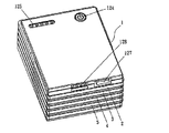
図5〜7に示すように、使用時には、該電源制御モジュール1と該単一のバッテリーユニット2とを組合せた後、2個目の単一のバッテリーユニット3、3個目の単一のバッテリーユニット4、4個目の単一のバッテリーユニット5等を、それと対応する単一のバッテリーユニット2の収容設置空間内に順番にスライドして入れてセットする。
As shown in FIGS. 5 to 7, in use, after the power
さらに、上下に重ねられた各バッテリーユニットの該第二接続ポート25と該第三接続ポート26をそれぞれ対応させて電気的に接続し、定位して係合する。
Further, the
上記したように、本考案装置は、使用者のニーズに応じて、該単一のバッテリーユニット2、3、4、5等の数を増やすことができる。
As described above, the device of the present invention can increase the number of the
さらに、図5〜7に示すようにスライド機構をバッテリーユニットの拡充或いは減少結合の定位に用いるため、電力容量の増加を達成し、或いは適当に調整後は、ポータブルデジタル装置への適時充電或いは給電のために携帯しての外出に便利である。 Furthermore, as shown in FIGS. 5-7, since the slide mechanism is used for localization of expansion or reduction coupling of the battery unit, an increase in power capacity is achieved, or after appropriate adjustment, timely charging or power feeding to the portable digital device Convenient to go out for carrying.
図8、10に示すように、使用時には、別に該電源制御モジュール1の第一接続ポート126及び該単一のバッテリーユニット2、3、4、5の第三接続ポート26を、該殼体11、21背面に設置することもできる。
As shown in FIGS. 8 and 10, in use, the
これにより、該電源制御モジュール1と該単一のバッテリーユニット2及び他の単一のバッテリーユニット3、4、5とは、上下に重なる方式で組み合わされる。
Thereby, the power
上記の本考案名称と内容は、本考案技術内容の説明に用いたのみで、本考案を限定するものではない。本考案の精神に基づく等価応用或いは部品(構造)の転換、置換、数量の増減はすべて、本考案の保護範囲に含むものとする。 The names and contents of the present invention described above are only used for explaining the technical contents of the present invention, and do not limit the present invention. All equivalent applications based on the spirit of the present invention, parts (structures) conversion, replacement, and quantity increase / decrease shall be included in the protection scope of the present invention.
本考案は実用新案登録の要件である新規性を備え、従来の同類製品に比べ十分な進歩を有し、実用性が高く、社会のニーズに合致しており、産業上の利用価値は非常に大きい。 The present invention has the novelty that is a requirement for utility model registration, has sufficient progress compared to similar products of the past, has high practicality, meets the needs of society, and has a very high industrial utility value. large.
1 電源制御モジュール
11 殼体
12 回路板
121 充電制御回路
122 電源昇/降圧転換回路
123 電源管理回路
124 スイッチボタン
125 作動状態インジケーターユニット
126 第一接続ポート
127 電源入力ポート
128 電源出力ポート
13 定位孔
14 係合孔
2 単一のバッテリーユニット
21 殼体
22 収容設置空間
23 コントローラー
24 バッテリー
25 第二接続ポート
26 第三接続ポート
27 定位ブロック
28 係合フック
271 定位孔
281 係合孔
3 単一のバッテリーユニット
4 単一のバッテリーユニット
5 単一のバッテリーユニット
DESCRIPTION OF
Claims (5)
前記電源制御モジュールは、その殼体内に回路板を設置し、
該回路板上には、充電制御回路、電源昇/降圧転換回路、電源管理回路、スイッチボタン、作動状態インジケーターユニット、第一接続ポート、電源入力ポート、電源出力ポートを設置すると共に前記殼体のバッテリーユニットに相対する面には、定位孔及び係合孔を設置し、
前記単一のバッテリーユニットは、その殼体上に重ねられる電源制御モジュール又は他のバッテリーユニットに相対する面に、これら電源モジュール又はバッテリーユニットを重ねる収容設置空間を設け、
該単一のバッテリーユニットには、コントローラー、バッテリー、前記電源制御モジュールの第一接続ポートに接続する第二接続ポート、さらに重ね合わされる他のバッテリーユニットの第二接続ポートに接続する第三接続ポートを備え、
該コントローラーと該バッテリー、該第二接続ポート及び該第三接続ポートとは電気的に接続し、該第二接続ポートを上記電源制御モジュール又は重ね合わされる他のバッテリーユニットに相対する殼体の上記収容設置空間上に設置し、
該第三接続ポートは、該殼体の収容設置空間の片側に設置し、
該単一のバッテリーユニットは、該殼体の電源制御モジュール又は重ね合わされる他のバッテリーユニットに相対する収容設置空間上に、定位ブロック及び係合フックを設置すると共に、その反対面には、重ね合わされる他のバッテリーユニットの該定位ブロック及び該係合フック位置に対応して定位孔及び係合孔を設置し、
前記電源制御モジュールを単一のバッテリーユニットに重ねてその収容空間にスライドさせて収容させることにより、その定位孔及び係合孔をそれぞれバッテリーユニットの定位ブロック及び係合フックに係合して結合させ、電源制御モジュールの第一接続ポートと単一のバッテリーユニットの第二接続ポートとを接続させ、さらに他のバッテリーユニットを重ねて同様に結合すると共にその第三接続ポートを該他のバッテリーユニットの第三接続ポートを接続させることにより、一以上のバッテリーユニットを重ねて結合することを可能としたことを特徴とする拡充式モバイル電源装置。 It consists of a power control module and one or more single battery units,
The power supply control module has a circuit board installed in its housing,
On the circuit board, a charging control circuit, a power up / down switching circuit, a power management circuit, a switch button, an operation state indicator unit, a first connection port, a power input port, a power output port are installed and the casing is On the surface facing the battery unit, a stereotaxic hole and an engagement hole are installed,
The single battery unit is provided on the surface facing the power control module or other battery unit stacked on the housing with a housing installation space for stacking these power modules or battery units,
The single battery unit includes a controller, a battery, a second connection port connected to the first connection port of the power control module, and a third connection port connected to the second connection port of another battery unit to be overlaid. With
The controller and the battery, the second connection port, and the third connection port are electrically connected, and the second connection port is connected to the power control module or the other battery unit to be overlaid on the casing. Installed on the accommodation installation space,
The third connection port is installed on one side of the housing housing installation space,
The single battery unit has a stereotaxic block and an engagement hook installed on the housing installation space facing the power control module of the enclosure or other battery unit to be overlaid, and on the opposite side thereof A positioning hole and an engagement hole corresponding to the positioning block and the engagement hook position of another battery unit to be installed,
The power supply control module is stacked on a single battery unit and slid into the storage space, and the localization hole and the engagement hole are engaged and coupled to the localization block and the engagement hook of the battery unit, respectively. The first connection port of the power control module and the second connection port of the single battery unit are connected, and another battery unit is overlapped and similarly coupled, and the third connection port is connected to the other battery unit. An expandable mobile power supply device characterized in that one or more battery units can be overlapped and joined by connecting a third connection port.
該充電制御回路、該昇/降圧転換回路、該電源管理回路間は、回路接続を構成し、
該電源管理回路と該スイッチボタン及び該作動状態インジケーターユニットとは電気的接続を構成し、
該電源昇/降圧転換回路と該電源出力ポート、該第一接続ポートとは電気的接続を構成したことを特徴とする請求項1に記載の拡充式モバイル電源装置。 The power input port of the power control module and the charge control circuit are electrically connected,
The charge control circuit, the step-up / step-down conversion circuit, and the power supply management circuit constitute a circuit connection,
The power management circuit, the switch button and the operation state indicator unit constitute an electrical connection,
2. The expandable mobile power supply device according to claim 1, wherein the power supply up / down conversion circuit, the power supply output port, and the first connection port constitute an electrical connection.
外部から電源接続し、押釦操作し、或いは目視することができるようにしたことを特徴とする請求項1に記載の拡充式モバイル電源装置。 The switch button on the circuit board in the power control module, the operation state indicator unit, the first connection port, the power input port and the power output port are exposed outside the housing of the power control module,
2. The expandable mobile power supply device according to claim 1, wherein a power supply is connected from outside, a push button is operated, or visual observation is possible.
該電源制御モジュールの電源出力ポートは、充電或いは給電が必要なポータブルデジタル機器の給電端と接続し、充電或いは給電を行うことを特徴とする請求項1に記載の拡充式モバイル電源装置。 Connect the adapter terminal to the power input port of the power control module, and input DC power to the power control module.
2. The expandable mobile power supply device according to claim 1, wherein the power output port of the power control module is connected to a power supply terminal of a portable digital device that needs to be charged or supplied to perform charging or power supply.
これにより、該電源制御モジュールと該単一のバッテリーユニット及び他の単一のバッテリーユニットとは、上下に重なる方式で組み合わされたことを特徴とする請求項1に記載の拡充式モバイル電源装置。 A first connection port of the power control module and a third connection port of a single battery unit superimposed on the first connection port are installed on the rear surface of the housing;
Accordingly, the power supply control module, the single battery unit, and the other single battery unit are combined in a vertically overlapping manner, and the expandable mobile power supply device according to claim 1.
Priority Applications (2)
| Application Number | Priority Date | Filing Date | Title |
|---|---|---|---|
| CN2011205265000U CN202474891U (en) | 2011-12-15 | 2011-12-15 | Extended mobile power supply device |
| JP2012002094U JP3176456U (en) | 2011-12-15 | 2012-04-10 | Expandable mobile power supply |
Applications Claiming Priority (2)
| Application Number | Priority Date | Filing Date | Title |
|---|---|---|---|
| CN2011205265000U CN202474891U (en) | 2011-12-15 | 2011-12-15 | Extended mobile power supply device |
| JP2012002094U JP3176456U (en) | 2011-12-15 | 2012-04-10 | Expandable mobile power supply |
Publications (1)
| Publication Number | Publication Date |
|---|---|
| JP3176456U true JP3176456U (en) | 2012-06-21 |
Family
ID=51301487
Family Applications (1)
| Application Number | Title | Priority Date | Filing Date |
|---|---|---|---|
| JP2012002094U Expired - Lifetime JP3176456U (en) | 2011-12-15 | 2012-04-10 | Expandable mobile power supply |
Country Status (2)
| Country | Link |
|---|---|
| JP (1) | JP3176456U (en) |
| CN (1) | CN202474891U (en) |
Cited By (2)
| Publication number | Priority date | Publication date | Assignee | Title |
|---|---|---|---|---|
| CN104578330A (en) * | 2015-02-16 | 2015-04-29 | 李明渊 | Wireless charging mode mobile power supply |
| CN104882933A (en) * | 2015-06-02 | 2015-09-02 | 宁波奥斯达光电科技有限公司 | Combined type charge pal |
Families Citing this family (4)
| Publication number | Priority date | Publication date | Assignee | Title |
|---|---|---|---|---|
| CN107171151B (en) | 2016-03-07 | 2019-05-21 | 雅睿国际有限公司 | Conduction mechanism and voltage dynamic self-balancing energy storage device thereof |
| GB2584596B (en) * | 2019-03-22 | 2023-08-02 | Eaton Intelligent Power Ltd | Battery powered wearables |
| CN110912176A (en) * | 2019-12-09 | 2020-03-24 | 中国南方电网有限责任公司超高压输电公司 | High-reliability power supply method for converter valve controller |
| CN111900772B (en) * | 2020-07-16 | 2023-10-20 | 湖南炬神电子有限公司 | Mobile power supply and quick charge control system |
-
2011
- 2011-12-15 CN CN2011205265000U patent/CN202474891U/en not_active Expired - Fee Related
-
2012
- 2012-04-10 JP JP2012002094U patent/JP3176456U/en not_active Expired - Lifetime
Cited By (4)
| Publication number | Priority date | Publication date | Assignee | Title |
|---|---|---|---|---|
| CN104578330A (en) * | 2015-02-16 | 2015-04-29 | 李明渊 | Wireless charging mode mobile power supply |
| CN104578330B (en) * | 2015-02-16 | 2017-11-03 | 李明渊 | A kind of wireless charging type portable power source |
| CN104882933A (en) * | 2015-06-02 | 2015-09-02 | 宁波奥斯达光电科技有限公司 | Combined type charge pal |
| CN104882933B (en) * | 2015-06-02 | 2018-08-28 | 宁波奥斯达光电科技有限公司 | Combined charging is precious |
Also Published As
| Publication number | Publication date |
|---|---|
| CN202474891U (en) | 2012-10-03 |
Similar Documents
| Publication | Publication Date | Title |
|---|---|---|
| TWI441372B (en) | Extended Mobile Power Supply | |
| JP3176456U (en) | Expandable mobile power supply | |
| CN201893412U (en) | Rechargeable battery assembly with internal connection port and external connection port for charging/outputting operations | |
| US20080252251A1 (en) | System for recharging battery-operated devices | |
| US8665599B2 (en) | Portable external power-supplying device | |
| CN202651818U (en) | Multipath output mobile power supply | |
| CN102005799A (en) | Portable multifunctional power supply | |
| CN202997643U (en) | A mobile power supply | |
| CN103855763B (en) | Base and panel computer | |
| TWM413225U (en) | Solar Mobile power box | |
| WO2019179349A1 (en) | Super battery pack and power tool assembly | |
| KR101474392B1 (en) | Apparatus of secondary battery with extensible function | |
| KR200473025Y1 (en) | Portable external power-supplying device | |
| CN102157969B (en) | Portable charge device | |
| CN202127260U (en) | Hand-held electronic device capable of reversely discharging | |
| KR200478882Y1 (en) | Portable power pack | |
| TWM397037U (en) | Three-in-one lithium battery structure of portable power bank, power capacity detection and charger | |
| KR101523699B1 (en) | Battery pack pouch apparatus with charger and discharger | |
| JP3188034U (en) | Palm-type AC / DC portable power supply | |
| CN205141745U (en) | Combined type power supply unit | |
| TWM432190U (en) | Expanding type mobile power supply device | |
| CN203312834U (en) | Detachably portable power source | |
| KR200379930Y1 (en) | A portable feeder of multi-DC voltage | |
| CN202043060U (en) | Solar energy mobile power box | |
| JP3231992U (en) | Mobile battery charger |
Legal Events
| Date | Code | Title | Description |
|---|---|---|---|
| R150 | Certificate of patent or registration of utility model |
Free format text: JAPANESE INTERMEDIATE CODE: R150 |
|
| FPAY | Renewal fee payment (event date is renewal date of database) |
Free format text: PAYMENT UNTIL: 20150530 Year of fee payment: 3 |
|
| R250 | Receipt of annual fees |
Free format text: JAPANESE INTERMEDIATE CODE: R250 |