JP3152702U - Air freshener - Google Patents
Air freshener Download PDFInfo
- Publication number
- JP3152702U JP3152702U JP2009000949U JP2009000949U JP3152702U JP 3152702 U JP3152702 U JP 3152702U JP 2009000949 U JP2009000949 U JP 2009000949U JP 2009000949 U JP2009000949 U JP 2009000949U JP 3152702 U JP3152702 U JP 3152702U
- Authority
- JP
- Japan
- Prior art keywords
- fragrance
- lid
- gap
- circular
- outside air
- Prior art date
- Legal status (The legal status is an assumption and is not a legal conclusion. Google has not performed a legal analysis and makes no representation as to the accuracy of the status listed.)
- Expired - Lifetime
Links
- 239000002386 air freshener Substances 0.000 title description 8
- 239000003205 fragrance Substances 0.000 claims abstract description 110
- 238000009423 ventilation Methods 0.000 claims abstract description 16
- 238000001704 evaporation Methods 0.000 claims abstract description 11
- 238000005553 drilling Methods 0.000 claims abstract description 4
- 230000008878 coupling Effects 0.000 claims description 20
- 238000010168 coupling process Methods 0.000 claims description 20
- 238000005859 coupling reaction Methods 0.000 claims description 20
- 230000002093 peripheral effect Effects 0.000 claims description 15
- 230000008020 evaporation Effects 0.000 claims description 9
- 239000007788 liquid Substances 0.000 abstract description 11
- 238000009792 diffusion process Methods 0.000 abstract description 5
- 239000011162 core material Substances 0.000 description 31
- 239000000796 flavoring agent Substances 0.000 description 11
- 235000019634 flavors Nutrition 0.000 description 11
- 238000004891 communication Methods 0.000 description 7
- 230000004048 modification Effects 0.000 description 5
- 238000012986 modification Methods 0.000 description 5
- 230000009471 action Effects 0.000 description 3
- 230000008901 benefit Effects 0.000 description 2
- 230000001427 coherent effect Effects 0.000 description 2
- 239000002781 deodorant agent Substances 0.000 description 2
- 238000010586 diagram Methods 0.000 description 2
- 230000000694 effects Effects 0.000 description 2
- 230000001681 protective effect Effects 0.000 description 2
- 230000007480 spreading Effects 0.000 description 2
- 230000005068 transpiration Effects 0.000 description 2
- 229920000178 Acrylic resin Polymers 0.000 description 1
- 239000004925 Acrylic resin Substances 0.000 description 1
- LFQSCWFLJHTTHZ-UHFFFAOYSA-N Ethanol Chemical compound CCO LFQSCWFLJHTTHZ-UHFFFAOYSA-N 0.000 description 1
- 230000004308 accommodation Effects 0.000 description 1
- 125000003118 aryl group Chemical group 0.000 description 1
- 230000001808 coupling effect Effects 0.000 description 1
- 230000007423 decrease Effects 0.000 description 1
- 239000000428 dust Substances 0.000 description 1
- 239000000835 fiber Substances 0.000 description 1
- 239000011521 glass Substances 0.000 description 1
- 210000004209 hair Anatomy 0.000 description 1
- 230000006872 improvement Effects 0.000 description 1
- 239000000203 mixture Substances 0.000 description 1
- 229920001225 polyester resin Polymers 0.000 description 1
- 239000004645 polyester resin Substances 0.000 description 1
- 230000001737 promoting effect Effects 0.000 description 1
- 239000011347 resin Substances 0.000 description 1
- 229920005989 resin Polymers 0.000 description 1
- 239000000126 substance Substances 0.000 description 1
- 229920003002 synthetic resin Polymers 0.000 description 1
- 239000000057 synthetic resin Substances 0.000 description 1
- 238000013022 venting Methods 0.000 description 1
- 239000002699 waste material Substances 0.000 description 1
Images


Abstract
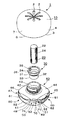
【課題】カバー装着状態における外気の流出入が円滑に行われ、芳香の放散効率を向上させることのできる芳香剤発散器を提供する。【解決手段】芳香剤発散器1は、上面に芳香を大気中に放散する8個の放出孔2を穿孔して円形壁4により下面に形成される円形開口部3を有した蓋体10と、液体芳香剤を内蔵した収容部41の上面44中央に形成された環状突起42の開口部43から芳香剤5を吸引する吸上芯20の上面22を突出させて芳香剤を蒸発させる容器本体40とからなる。円弧状部50は蓋体10の円形開口部3と結合密着して外気を遮断し、通気用切欠部60と円形開口部3との間隙は外気の間隙通気路を形成する。垂直壁62と円形開口部3との間隙を通気口として流入する外気が間隙通気路を通じて傾斜壁61により蓋体10内側に誘導されて吸上芯20の上面22側に流通する。【選択図】図1The present invention provides a fragrance diffuser capable of smoothly flowing in and out of outside air in a cover-mounted state and improving fragrance diffusion efficiency. A fragrance diffuser 1 has a lid 10 having a circular opening 3 formed in a lower surface by a circular wall 4 by drilling eight discharge holes 2 for diffusing fragrance into the atmosphere on the upper surface. A container main body for evaporating the fragrance by projecting the upper surface 22 of the suction core 20 for sucking the fragrance 5 from the opening 43 of the annular protrusion 42 formed at the center of the upper surface 44 of the housing 41 containing the liquid fragrance. 40. The arcuate portion 50 is coupled and tightly connected to the circular opening 3 of the lid body 10 to block outside air, and the gap between the ventilation notch 60 and the circular opening 3 forms a gap air passage for outside air. Outside air that flows in with the gap between the vertical wall 62 and the circular opening 3 as a vent is guided to the inside of the lid body 10 by the inclined wall 61 through the gap vent and flows to the upper surface 22 side of the suction core 20. [Selection] Figure 1
Description
本考案は、室内やトイレ、あるいは自動車内などで使用される芳香剤を収容し、芳香剤からの芳香を大気中に放散させる芳香剤発散器に関する。 The present invention relates to a fragrance diffuser that contains a fragrance used in a room, a toilet, an automobile, or the like and diffuses the fragrance from the fragrance into the atmosphere.
この種の芳香剤発散器には、例えば、特許文献1及び2に開示されているように、壷型やポット形状の容器に液状芳香剤を収容し、一端を芳香剤に浸漬した吸上芯の開放端から芳香気体を放散させるものが使用されている。
特許文献1の場合、アルコールランプ型の芳香剤容器の中央に芯材を装着し、その上から半球状カバーを冠着している。また、特許文献2においては、偏平状の芳香剤容器に液体吐出管を装着し、その上からカバー部材を冠着している。特許文献2の容器は押圧変形可能であり、容器の変形で押し出された芳香剤液は、液体吐出管の先端から溢れ出して、その先端付近に設けた蒸散補助部材に吸収される。
In this type of fragrance diffuser, for example, as disclosed in
In the case of Patent Document 1, a core material is attached to the center of an alcohol lamp-type fragrance container, and a hemispherical cover is attached from above. In
芳香剤発散器においては、芯材ないし蒸散補助部材を大気中に露出させると、塵埃の付着のおそれがあると共に芳香剤の蒸発が促進されすぎて芳香剤の消耗が早くなってしまうため、上記カバー部材を冠着している。カバー部材には芳香の通気孔が形成され、芳香剤から蒸発した芳香を大気中に放散させている。 In the fragrance diffuser, if the core material or the transpiration assisting member is exposed to the atmosphere, there is a risk of adhesion of dust and the evaporation of the fragrance is promoted too much, so that the consumption of the fragrance is accelerated. A cover member is attached. The cover member is formed with a fragrance vent hole to diffuse the fragrance evaporated from the fragrance into the atmosphere.
特許文献2の容器構造では、液体吐出管の先端から、あるいは蒸散補助部材に吸収された芳香剤から芳香気体が自然蒸散されるものの、上記カバー部材には、液体吐出管の直上に円形孔と放射状溝を形成しているだけであるため、外気の流出入が生じにくく、芳香の放散効率が低下する問題を生ずる。
また、特許文献1の半球状カバーでは、芯材の直上を避けて、先端周りのカバー側面にエアー通気孔を穿設している。この場合、エアー通気孔から入った外気が芯材の先端付近を通過し、別の通気孔より略水平方向に流出するものの、別々の通気孔からの流入エアーどうしが衝突したりして、外気の流出入が十分に生じにくい問題があった。
In the container structure of
Further, in the hemispherical cover of Patent Document 1, an air vent hole is formed in the side surface of the cover around the tip, avoiding directly above the core material. In this case, outside air that has entered through the air vents passes near the tip of the core material and flows out from the other vents in a substantially horizontal direction, but the inflowing air from the separate vents collides with the outside air. There was a problem that it was difficult for the inflow and outflow to occur sufficiently.
本考案は、上記課題に鑑みてなされたものであり、カバー装着状態における外気の流出入が円滑に行われ、芳香の放散効率を向上させることのできる芳香剤発散器を提供することを目的とする。 The present invention has been made in view of the above problems, and an object of the present invention is to provide a fragrance diffuser capable of smoothly flowing in and out of the outside air in a cover-mounted state and improving the fragrance diffusion efficiency. To do.
本考案は上記課題を解決するために為されたものであり、本考案の第1の形態は、上面に芳香を大気中に放散する複数の放出孔を穿孔して円形壁により下面に形成される円形開口部を有した蓋体と、芳香剤を内蔵した収容部の上面中央に形成された環状突起の開口部から前記芳香剤を吸引する吸上芯の上面を突出させて前記芳香剤を蒸発させる容器本体とから構成され、前記収容部の上面周側下部の周方向に円弧状部と通気用切欠部を交互に複数個形成し、前記容器本体を前記蓋体で閉鎖したときに、前記円弧状部は前記蓋体の前記円形開口部と結合密着して外気を遮断し、前記通気用切欠部と前記円形開口部との間隙は外気の間隙通気路を形成し、前記間隙通気路から流入する外気が前記吸上芯からの前記芳香剤の蒸発を促進させながら前記放出孔から流出して前記芳香を大気中に放散させる芳香剤発散器である。 The present invention has been made to solve the above-mentioned problems, and the first embodiment of the present invention is formed on the lower surface by a circular wall by drilling a plurality of discharge holes for releasing fragrance into the atmosphere on the upper surface. The upper surface of the suction core for sucking the fragrance is projected from the opening of the lid having a circular opening and the annular protrusion formed at the center of the upper surface of the housing portion containing the fragrance. When the container body is configured to evaporate, alternately forming a plurality of arcuate parts and ventilation notches in the circumferential direction of the lower part on the upper surface side of the housing part, and closing the container body with the lid, The arcuate portion is coupled and closely contacted with the circular opening of the lid to block outside air, and a gap between the ventilation notch and the circular opening forms a gap air passage for outside air, and the gap ventilation passage The outside air flowing in from the suction core promotes the evaporation of the fragrance from the wick. A fragrance diffuser that flows out from the discharge hole and diffuses the fragrance into the atmosphere.
本考案の第2の形態は、第1の形態において、前記上面周側下部は、上面周縁と、前記上面周縁から下向き段差を介して前記上面周縁を包囲するように形成された環状面と、前記環状面外周縁からなり、前記円弧状部は前記上面周縁の小円弧状部と前記環状面外周縁の大円弧状部からなり、前記通気用切欠部は前記上面周縁から前記環状面へと外向下方傾斜する傾斜壁と前記環状面外周縁を裁断状に切欠いた垂直壁からなり、前記垂直壁と前記円形開口部との間隙が通気口となり、前記蓋体の前記円形壁と前記傾斜壁との間隙が前記間隙通気路となり、前記通気口から流入する外気が前記傾斜壁により誘導されて前記吸上芯の上面へと流通する芳香剤発散器である。 According to a second aspect of the present invention, in the first aspect, the lower portion on the upper surface side is an upper surface periphery, and an annular surface formed so as to surround the upper surface periphery through a step downward from the upper surface periphery; The outer circumferential edge of the annular surface, the arc-shaped portion is composed of a small arc-shaped portion of the upper surface periphery and a large arc-shaped portion of the outer periphery of the annular surface, and the ventilation notch portion extends from the upper surface periphery to the annular surface. It consists of an inclined wall that is inclined downward and a vertical wall in which the outer peripheral edge of the annular surface is cut out in a cut shape, and a gap between the vertical wall and the circular opening serves as a vent, and the circular wall and the inclined wall of the lid Is a fragrance diffuser in which outside air flowing from the vent is guided by the inclined wall and flows to the upper surface of the suction core.
本考案の第3の形態は、第2の形態において、前記小円弧状部と前記環状面の間に円弧状溝が周方向に刻設され、前記円弧状溝の端部に止部が形成され、円形壁の内面周方向に結合用突起が形成され、前記結合用突起を前記円弧状溝に係合して前記蓋体を回動し、前記結合用突起が前記止部により回動を阻止されて、前記蓋体と前記容器本体との結合が完成する芳香剤発散器である。 According to a third aspect of the present invention, in the second aspect, an arc-shaped groove is engraved in the circumferential direction between the small arc-shaped portion and the annular surface, and a stop is formed at an end of the arc-shaped groove. The coupling protrusion is formed in the inner circumferential direction of the circular wall, the lid is rotated by engaging the coupling protrusion with the arcuate groove, and the coupling protrusion is rotated by the stopper. A fragrance diffuser that is blocked to complete the connection between the lid and the container body.
本考案の第4の形態は、第2又は第3の形態において、複数の前記垂直壁のうち少なくとも対向する2面に摩擦生起用リブを2本以上突設した芳香剤発散器である。
The 4th form of this invention is the fragrance | flavor diffuser which provided the rib for
本考案の第5の形態は、第4の形態において、前記摩擦生起用リブは前記垂直壁に形成された等間隔縦状リブ、間隔漸増型縦状リブ又は波紋状リブである芳香剤発散器である。 According to a fifth aspect of the present invention, there is provided a fragrance diffuser according to the fourth aspect, wherein the friction generating rib is an equally spaced vertical rib, a gradually increasing vertical rib or a rippled rib formed on the vertical wall. It is.
本考案の第6の形態は、第2〜第5のいずれかの形態において、前記円形壁の円形端面と前記環状面とが接合したとき、前記円形壁の外表面と前記容器本体の外表面とが面一に形成される芳香剤発散器である。 According to a sixth aspect of the present invention, in any one of the second to fifth aspects, when the circular end surface of the circular wall and the annular surface are joined, the outer surface of the circular wall and the outer surface of the container body Is a fragrance diffuser that is formed flush with each other.
本考案の第7の形態は、第2〜第5のいずれかの形態において、前記環状突起に中間キャップを内嵌させ、前記中間キャップは前記吸上芯に外接する縮径部と前記環状突起に内接する拡径部と前記縮径部及び前記拡径部の間に連接されるテーパ部からなり、前記拡径部の内面に収容部側孔と蓋体側孔を有する連通部を突設し、前記連通部により前記収容部と前記蓋体内部とを連通する芳香剤発散器である。 According to a seventh aspect of the present invention, in any one of the second to fifth aspects, an intermediate cap is fitted into the annular protrusion, and the intermediate cap is connected to the reduced diameter portion circumscribing the suction core and the annular protrusion. A diameter-increasing portion that is inscribed in, a tapered portion that is connected between the reduced-diameter portion and the enlarged-diameter portion, and a communication portion that has a housing-side hole and a lid-side hole is provided on the inner surface of the enlarged-diameter portion. A fragrance diffuser that communicates the accommodating portion and the inside of the lid by the communicating portion.
本考案の第8の形態は、第1〜第7のいずれかの形態において、前記環状突起の開口部にキャップを冠着して、芳香発散不要時に前記芳香剤の蒸発を防止する芳香剤発散器である。 According to an eighth aspect of the present invention, in any one of the first to seventh aspects, a fragrance divergence is achieved by attaching a cap to the opening of the annular protrusion to prevent evaporation of the fragrance when the fragrance divergence is unnecessary. It is a vessel.
本考案は、室内や車内等における空気流が横方向の流れよりも下方から上方に生ずる傾向にある点に着目して為されたものである。
本考案の第1の形態によれば、芳香剤を内蔵した前記収容部の上面周側下部の周方向に円弧状部と通気用切欠部を交互に複数個形成し、前記容器本体を前記蓋体で閉鎖したときに、前記円弧状部は前記蓋体の前記円形開口部と結合密着して外気を遮断し、前記通気用切欠部と前記円形開口部との間隙は外気の間隙通気路を形成し、前記間隙通気路から流入する外気が前記吸上芯からの前記芳香剤の蒸発を促進させながら前記放出孔から流出して前記芳香を大気中に放散させるので、単に前記蓋体に前記放出孔を形成しただけでは芳香を十分に放散させる空気流が生じないが、前記間隙通気路を通じて前記蓋体の内部を下側から前記吸上芯の上面を通過して前記放出孔より流出するといった外気の流れを生じさせることができる。従って、前記蓋体により前記容器本体を閉鎖したカバー装着状態において、室内等における下方から上方に生ずる空気流を利用しながら芳香放散を円滑且つ効率的に行うことができる。
The present invention has been made by paying attention to the point that the air flow in the room or in the vehicle tends to occur from the lower side to the upper side than the horizontal flow.
According to the first aspect of the present invention, a plurality of arc-shaped portions and ventilation cutout portions are alternately formed in the circumferential direction of the lower portion on the upper surface side of the housing portion containing the fragrance, and the container body is attached to the lid. When the body is closed, the arc-shaped portion is tightly coupled with the circular opening of the lid to block outside air, and the gap between the ventilation notch and the circular opening serves as a gap air passage for outside air. Formed and the outside air flowing in from the gap ventilation passage flows out of the discharge hole while accelerating the evaporation of the fragrance from the suction core and dissipates the fragrance into the atmosphere. An air flow that sufficiently dissipates the fragrance does not occur just by forming the discharge hole, but flows out from the discharge hole through the gap vent passage from the lower side through the upper surface of the suction core through the gap air passage. The flow of outside air can be generated. Therefore, in a cover-mounted state in which the container body is closed by the lid body, it is possible to smoothly and efficiently dissipate fragrance while using an air flow generated upward from below in a room or the like.
本考案に係る芳香剤には、芳香成分を主組成としたものに限らず、消臭成分を含む消臭剤を使用することができる。また、芳香剤の形態には液体に限らず、香料等がゲル状の揮発物質からなるものも含まれる。 The fragrance according to the present invention is not limited to the fragrance component as a main composition, and a deodorant containing a deodorant component can be used. In addition, the form of the fragrance is not limited to a liquid, but includes a fragrance made of a gel volatile substance.
本考案の第2の形態によれば、前記蓋体の前記円形壁と前記傾斜壁との間隙からなる前記間隙通気路を通じて、前記垂直壁と前記円形開口部との間隙である前記通気口から外気が流入し、前記傾斜壁により誘導されて前記吸上芯の上面へと流通するので、前記蓋体によるカバー装着状態において、室内等における下方から上方に生ずる空気流を利用した外気の流れを生じて、芳香放散を円滑且つ効率的に行うことができる。 According to the second aspect of the present invention, from the air vent which is a gap between the vertical wall and the circular opening through the gap air passage formed by a gap between the circular wall and the inclined wall of the lid. Since the outside air flows in and is guided by the inclined wall and flows to the upper surface of the suction core, the outside air flow utilizing the air flow generated from the lower side in the room or the like in the cover mounted state by the lid body is used. As a result, the fragrance can be diffused smoothly and efficiently.
本考案の第3の形態によれば、前記小円弧状部と前記環状面の間に円弧状溝が周方向に刻設され、前記円弧状溝の端部に止部が形成され、円形壁の内面周方向に結合用突起が形成され、前記結合用突起を前記円弧状溝に係合して前記蓋体を回動し、前記結合用突起が前記止部により回動を阻止されて、前記蓋体と前記容器本体との結合が完成するので、前記容器本体の前記円弧状部と前記蓋体の前記円形開口部との結合密着を確実にしながら前記間隙通気路を形成、確保することができる。 According to a third aspect of the present invention, an arc-shaped groove is engraved in the circumferential direction between the small arc-shaped portion and the annular surface, and a stop portion is formed at an end of the arc-shaped groove. A coupling protrusion is formed in a circumferential direction of the inner surface, the coupling protrusion is engaged with the arcuate groove to rotate the lid body, and the coupling protrusion is prevented from rotating by the stopper, Since the coupling between the lid body and the container body is completed, the gap air passage is formed and secured while ensuring the tight contact between the arcuate portion of the container body and the circular opening of the lid body. Can do.
本考案の第4の形態によれば、複数の前記垂直壁のうち少なくとも対向する2面に摩擦生起用リブを2本以上突設したので、前記摩擦生起用リブを指で掴んで前記蓋体を回動することにより、手や指が滑らず前記蓋体と前記容器本体との結合を確実に行うことができる。前記摩擦生起用リブの形成は前記対向する2面のみでもよいが、前記垂直壁を2対以上設け、交差状に配置した他の2面にも形成して4面、8面等にリブ形成してもよい。 According to the fourth aspect of the present invention, since two or more friction generating ribs protrude from at least two opposing surfaces of the plurality of vertical walls, the lid is obtained by grasping the friction generating ribs with fingers. By rotating the, the lid and the container body can be reliably coupled without slipping of hands or fingers. The friction generating ribs may be formed only on the two opposing surfaces, but two or more pairs of the vertical walls are provided and formed on the other two surfaces arranged in an intersecting manner to form ribs on four surfaces, eight surfaces, etc. May be.
本考案の第5の形態によれば、前記摩擦生起用リブとして、前記垂直壁に形成された等間隔縦状リブ、間隔漸増型縦状リブ又は波紋状リブを用いることにより、前記蓋体の回動操作を円滑に行え、しかも美感に優れたリブ紋様により容器デザイン効果の向上にも寄与する。 According to the fifth aspect of the present invention, by using an equally spaced vertical rib, a gradually increasing vertical rib or a rippled rib formed on the vertical wall as the friction generating rib, The rib pattern can be rotated smoothly and has excellent aesthetics, contributing to improved container design effects.
本考案の第6の形態によれば、前記円形壁の円形端面と前記環状面とが接合したとき、前記円形壁の外表面と前記容器本体の外表面とが面一に形成され、凹凸が解消され把持しやすくなっているので、前記蓋体を装着したカバー状態で持ち運びする際に落下しにくく、しかも全体としてまとまりのある美感を生じさせる外観形状を具現化することができる。 According to the sixth aspect of the present invention, when the circular end surface of the circular wall and the annular surface are joined, the outer surface of the circular wall and the outer surface of the container body are formed to be flush with each other. Since it is eliminated and easy to grip, it is possible to embody an external appearance shape that does not easily drop when carried in a cover state with the lid attached, and that produces a coherent aesthetics as a whole.
本考案の第7の形態によれば、前記環状突起に中間キャップを内嵌させ、前記中間キャップは前記吸上芯に外接する縮径部と前記環状突起に内接する拡径部と前記縮径部及び前記拡径部の間に連接されるテーパ部からなり、前記拡径部の内面に収容部側孔と蓋体側孔を有する連通部を突設し、前記連通部により前記収容部と前記蓋体内部とを連通するので、前記中間キャップにより前記吸上芯を安定支持すると共に、前記収容部と前記蓋体内部の圧力差をなくして収容芳香剤の液面の上下動が発生せず、定常的に芳香発散を行わせることができる。 According to a seventh aspect of the present invention, an intermediate cap is fitted into the annular protrusion, and the intermediate cap has a reduced diameter portion circumscribing the suction core, an enlarged diameter portion inscribed in the annular protrusion, and the reduced diameter. And a tapered portion connected between the enlarged-diameter portion, a communicating portion having a housing-side hole and a lid-side hole is provided on the inner surface of the enlarged-diameter portion, and the communicating portion and the Since the inside of the lid communicates with each other, the suction cap is stably supported by the intermediate cap, and the pressure difference between the inside of the housing and the lid is eliminated, and the liquid level of the contained air freshener does not occur. The fragrance can be steadily emitted.
本考案の第8の形態によれば、芳香発散不要時には前記環状突起の開口部に前記キャップを冠着することにより前記芳香剤の蒸発を防止することができるので、芳香剤を無駄なく経済的に使用することができる。 According to the eighth aspect of the present invention, when the fragrance divergence is not required, the fragrance can be prevented from evaporating by attaching the cap to the opening of the annular projection, so that the fragrance can be used economically. Can be used for
以下、本考案の実施形態を図面に基づいて説明する。
図1は本考案に係る芳香剤発散器1の分解斜視図である。図2は芳香剤発散器1の組立全体外観図である。図3は芳香剤発散器1の縦断面図である。
Embodiments of the present invention will be described below with reference to the drawings.
FIG. 1 is an exploded perspective view of a fragrance diffuser 1 according to the present invention. FIG. 2 is an overall external view of the fragrance diffuser 1 assembled. FIG. 3 is a longitudinal sectional view of the fragrance diffuser 1.
芳香剤発散器1は、上面に芳香を大気中に放散する8個の放出孔2を穿孔して円形壁4により下面に形成される円形開口部3を有した蓋体10と、液体芳香剤5を内蔵した収容部41の上面44中央に形成された環状突起42の開口部43から芳香剤5を吸引する吸上芯20の上面22を突出させて芳香剤を蒸発させる容器本体40とから構成されている。芳香剤発散器1の各部材は合成樹脂の成形品で形成されている。容器本体40はガラス容器で成形してもよい。吸上芯20は例えば、アクリル樹脂、ポリエステル樹脂等の樹脂繊維毛を束ねた吸液性棒状芯材からなる。
The fragrance diffuser 1 includes a
図7は容器本体40の平面図である。容器本体40は、上面44により上部が閉塞された、略椀状の収容部41を備え、上面44中央に環状突起42が一体的に垂設されている。収容部41の上面周側下部45には、その周方向に円弧状部50と通気用切欠部60が4個ずつ、交互に形成されている。
FIG. 7 is a plan view of the
上面周側下部45は、上面周縁46と、上面周縁46から下向き段差47を介して上面周縁46を包囲するように形成された環状面48と、環状面48の外周縁49からなる。円弧状部50は上面周縁46の小円弧状部51と環状面外周縁49の大円弧状部52からなる。通気用切欠部60は上面周縁46から環状面48へと外向下方傾斜する傾斜壁61と環状面外周縁49を裁断状に切欠いた垂直壁62からなる。
The upper surface peripheral side
環状突起42の開口部43外周には、保護用キャップ90(後述の図5参照)を螺着するためのネジ部が形成されている。開口部43には、吸上芯20が中間キャップ30を介して内嵌、挿着される。中間キャップ30を介して内嵌された吸上芯20の下端部は芳香剤5に浸漬され、吸上芯の開放端は中間キャップ30より突出した状態になっている。
中間キャップ30は吸上芯20に外接する縮径部33と環状突起42に内接する拡径部31と縮径部33及び拡径部31の間に連接されるテーパ部32からなる。拡径部31の内面には、収容部側孔36と蓋体側孔35を有する連通部34が突設され、連通部34により収容部50と蓋体10内部とが連通している。
拡径部31の内面に突設された連通部34により、吸上芯20側面に軽圧をかけて支持する利点もある。従って、中間キャップ30は吸上芯20を安定支持すると共に、連通部34の連通作用により収容部50と蓋体10内部の圧力差をなくしているので、収容芳香剤5の液面の上下動が発生させずに、定常的に芳香発散を行わせることができる。また、拡径部31の拡径作用によって吸上芯20の突出側面の芳香発散面積を大きくすることができる。
A screw portion for screwing a protective cap 90 (see FIG. 5 described later) is formed on the outer periphery of the
The
There is also an advantage that a light pressure is applied to the side surface of the
図6は円形開口部3側から見た、前記芳香剤発散器の蓋体10の平面図である。蓋体10は略椀形状を有し、上面には8個の放出孔2が放射状に穿設されている。下面の円形開口部3の内周縁には、容器本体40と係合して結合させるための結合用突起8が等間隔で4個突設されている。容器本体40の小円弧状部51と環状面48の間には、円弧状溝70が周方向に刻設され、また円弧状溝70の端部に止部71が形成されている。
FIG. 6 is a plan view of the
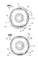
図8は蓋体10と容器本体40を接合した結合完成前後の状態を示す。図8の(8A)は結合完成前の状態を示し、同図(8B)は結合完成後の状態を示す。
蓋体10の結合用突起8を円弧状溝70に係合して、図示の時計回り方向Cに蓋体10を回動すると、結合用突起8が止部71により回動が阻止されて、蓋体10と容器本体40との結合が完成する。
FIG. 8 shows a state before and after the completion of the joining in which the
When the
蓋体10と容器本体40との結合によって、容器本体40を蓋体10により閉鎖したカバー装着状態においては、吸上芯20から吸い上げた芳香剤が上面22及び吸上芯上部周面24から蒸発し、その揮発芳香は放出孔2から外気に向けて放散される。
In the cover mounting state in which the
図4は芳香剤発散器1における芳香放散作用の説明図である。上記カバー装着状態においては、円弧状部50は蓋体10の円形開口部3と結合密着して外気を遮断し、通気用切欠部60と円形開口部3との間隙は外気の間隙通気路11を形成している。即ち、垂直壁62と円形開口部3との間隙が通気口9となり、蓋体10の円形壁4と傾斜壁61との間隙が間隙通気路11となっている。矢印Aで示すように、通気口9から流入する外気が傾斜壁61により蓋体10内側に誘導されて吸上芯20の上面22側に流通する。この流入外気は、芳香を発散させている上面22及び吸上芯上部周面24に流れていくため、吸上芯20からの芳香剤5の蒸発を促進させると共に、矢印Bで示すように、放出孔2からの外部流出も促して発散芳香を大気中に円滑、且つ効率的に放散させることができる。特に、上記カバー装着状態においては、結合用突起8と円弧状溝70の止部71との結合作用により、容器本体40の円弧状部50と蓋体10の円形開口部3との結合密着を確実にしながら間隙通気路11を形成して、確保することができ、芳香発散を安定的に生じさせる空気流を形成することができる。
FIG. 4 is an explanatory view of the fragrance diffusion action in the fragrance diffuser 1. In the cover-mounted state, the
図2に示すように、芳香剤発散器1においては、蓋体10の円形壁4の円形端面6と、容器本体40の環状面48とが接合したとき、円形壁4の外表面7と容器本体40の外表面75とが面一に形成されている。従って、芳香剤発散器1は、蓋体10を装着したカバー状態では、凹凸のない把持しやすい外観形態となっているので、持ち運びする際に落下しにくく、しかも全体としてまとまりのある美感を生じさせる、果物様の外観形状を具備している。
As shown in FIG. 2, in the fragrance diffuser 1, when the
容器本体40には4個の垂直壁62が形成されているが、そのうち対向する2面側の垂直壁62には、20本の摩擦生起用リブ82が突設されている。摩擦生起用リブ82は等間隔縦状に刻設されたリブである。摩擦生起用リブ82を指で掴んで蓋体10を回動することにより、指が滑らず蓋体10と容器本体40との結合、解除を確実に行うことができる。
Four
図9は摩擦生起用リブの変形例を示す。図9の(9A)は摩擦生起用リブとして対向2面に波紋状リブ84を垂直壁62に突設した変形例を示す。同図(9B)は摩擦生起用リブとして対向4面に間隙漸増型縦状リブ85を垂直壁62に突設した変形例を示す。
摩擦生起用リブとして、(9A)の波紋状リブ84又は(9B)の間隔漸増型縦状リブ85を用いることにより、等間隔縦状リブと同様に、蓋体10の回動操作を円滑に行え、しかも美感に優れたリブ紋様により容器デザイン効果の向上にも寄与する。(9B)に示すように、摩擦生起用リブの形成は対向する2面のみでもよいが、4個の垂直壁62の全てに形成してもよい。
FIG. 9 shows a modification of the friction generating rib. (9A) of FIG. 9 shows a modification in which ripple
By using the
図5は芳香剤発散器1に保護用キャップ90を冠着したときの縦断面を示す。芳香剤発散器1を使用しないときは、環状突起42の開口部43にキャップ90を螺着して冠着すると、芳香剤5の蒸発を防止することができる。使用時には図3等に示すように、キャップ90を環状突起42から取り外して、吸上芯20の上部を露出させ芳香発散を行うことができる。従って、キャップ90の着脱により、必要時のみ芳香放散させ、無駄なく経済的に芳香剤を消費させることができる。
FIG. 5 shows a longitudinal section when the
本考案によれば、芳香剤の放散効率を向上させた芳香剤発散器を提供することができる。 ADVANTAGE OF THE INVENTION According to this invention, the fragrance | flavor diffuser which improved the diffusion efficiency of the fragrance | flavor can be provided.
1 芳香剤発散器
2 放出孔
3 円形開口部
4 円形壁
5 芳香剤
6 円形端面
7 外表面
8 結合用突起
9 通気口
10 蓋体
11 間隙通気路
20 吸上芯
22 上面
24 吸上芯上部周面
30 中間キャップ
31 拡径部
32 テーパ部
33 縮径部
34 連通部
35 蓋体側孔
36 収容部側孔
40 容器本体
41 収容部
42 環状突起
43 開口部
44 上面
45 上面周側下部
46 上面周縁
47 下向き段差
48 環状面
49 外周縁
50 円弧状部
51 小円弧状部
52 大円弧状部
60 通気用切欠部
61 傾斜壁
62 垂直壁
70 円弧状溝
71 止部
75 外表面
82 摩擦生起用リブ
84 波紋状リブ
85 間隙漸増型縦状リブ
90 キャップ
A 矢印
B 矢印
C 時計回り方向
DESCRIPTION OF SYMBOLS 1
Claims (8)
前記収容部の上面周側下部の周方向に円弧状部と通気用切欠部を交互に複数個形成し、
前記容器本体を前記蓋体で閉鎖したときに、前記円弧状部は前記蓋体の前記円形開口部と結合密着して外気を遮断し、
前記通気用切欠部と前記円形開口部との間隙は外気の間隙通気路を形成し、
前記間隙通気路から流入する外気が前記吸上芯からの前記芳香剤の蒸発を促進させながら前記放出孔から流出して前記芳香を大気中に放散させることを特徴とする芳香剤発散器。 A lid with a circular opening formed in the lower surface by a circular wall by drilling a plurality of discharge holes to dissipate the fragrance into the atmosphere on the upper surface, and a ring formed in the center of the upper surface of the housing portion containing the fragrance A container body that evaporates the fragrance by projecting the upper surface of the suction core that sucks the fragrance from the opening of the protrusion;
A plurality of arcuate portions and ventilation cutout portions are alternately formed in the circumferential direction of the lower portion on the upper surface side of the housing portion,
When the container body is closed with the lid body, the arc-shaped portion is bonded to the circular opening of the lid body to block outside air,
A gap between the ventilation notch and the circular opening forms a gap ventilation path for outside air,
A fragrance diffuser that discharges the fragrance into the atmosphere by flowing out from the discharge hole while outside air flowing in from the gap air passage promotes evaporation of the fragrance from the suction core.
Priority Applications (1)
| Application Number | Priority Date | Filing Date | Title |
|---|---|---|---|
| JP2009000949U JP3152702U (en) | 2009-02-24 | 2009-02-24 | Air freshener |
Applications Claiming Priority (1)
| Application Number | Priority Date | Filing Date | Title |
|---|---|---|---|
| JP2009000949U JP3152702U (en) | 2009-02-24 | 2009-02-24 | Air freshener |
Publications (1)
| Publication Number | Publication Date |
|---|---|
| JP3152702U true JP3152702U (en) | 2009-08-13 |
Family
ID=54857003
Family Applications (1)
| Application Number | Title | Priority Date | Filing Date |
|---|---|---|---|
| JP2009000949U Expired - Lifetime JP3152702U (en) | 2009-02-24 | 2009-02-24 | Air freshener |
Country Status (1)
| Country | Link |
|---|---|
| JP (1) | JP3152702U (en) |
Cited By (2)
| Publication number | Priority date | Publication date | Assignee | Title |
|---|---|---|---|---|
| JP2016182203A (en) * | 2015-03-25 | 2016-10-20 | 小林製薬株式会社 | Chemical volatilizer for cabin |
| CN115038331A (en) * | 2019-12-06 | 2022-09-09 | S.C.约翰逊父子公司 | Emanator and method of using same |
-
2009
- 2009-02-24 JP JP2009000949U patent/JP3152702U/en not_active Expired - Lifetime
Cited By (3)
| Publication number | Priority date | Publication date | Assignee | Title |
|---|---|---|---|---|
| JP2016182203A (en) * | 2015-03-25 | 2016-10-20 | 小林製薬株式会社 | Chemical volatilizer for cabin |
| CN115038331A (en) * | 2019-12-06 | 2022-09-09 | S.C.约翰逊父子公司 | Emanator and method of using same |
| CN115038331B (en) * | 2019-12-06 | 2024-03-19 | S.C.约翰逊父子公司 | Dispenser and method of using same |
Similar Documents
| Publication | Publication Date | Title |
|---|---|---|
| US8851396B2 (en) | Dual scent air freshener with manual combiner | |
| US20120091221A1 (en) | Wick Diffuser | |
| JP2015527098A (en) | Centrifugal fan device | |
| US20110284655A1 (en) | Spill-proof aerator for low volatile compound solutions | |
| EP2588150A1 (en) | Devices and methods for improved delivery of volatile liquids | |
| MX2007001814A (en) | Volatile substance diffusing device. | |
| KR101500436B1 (en) | fragrance candle vessel | |
| JP3152702U (en) | Air freshener | |
| JP2010260587A (en) | Volatile liquid spreading apparatus | |
| JP5817089B2 (en) | Container with inner stopper | |
| JP6358465B2 (en) | Volatilization container | |
| JP3471429B2 (en) | Liquid air freshener container | |
| JP2017063898A (en) | Medicine volatilizing device | |
| JP3143839U (en) | Air freshener sprayer | |
| JP4153978B2 (en) | Aroma generator | |
| KR20170028109A (en) | Portable and rechargeable card-type diffusers and diffuser assemblies including the same | |
| JP2010259544A (en) | Volatile liquid diffuser | |
| JP2022002972A (en) | Chemical liquid vaporizer | |
| JP3155997U (en) | Air freshener sprayer with decorative lamp | |
| CN221887820U (en) | An umbrella handle capable of releasing fragrance | |
| JP2006288330A (en) | Chemical volatilization container | |
| JP2024109327A (en) | Air Freshener Bottle | |
| JP2007062784A (en) | Aroma generating apparatus | |
| JP2008183207A (en) | Shower | |
| JP3164113U (en) | Aroma / deodorant container |
Legal Events
| Date | Code | Title | Description |
|---|---|---|---|
| R150 | Certificate of patent or registration of utility model |
Free format text: JAPANESE INTERMEDIATE CODE: R150 |
|
| FPAY | Renewal fee payment (event date is renewal date of database) |
Free format text: PAYMENT UNTIL: 20120722 Year of fee payment: 3 |
|
| FPAY | Renewal fee payment (event date is renewal date of database) |
Free format text: PAYMENT UNTIL: 20120722 Year of fee payment: 3 |
|
| FPAY | Renewal fee payment (event date is renewal date of database) |
Free format text: PAYMENT UNTIL: 20150722 Year of fee payment: 6 |
|
| R250 | Receipt of annual fees |
Free format text: JAPANESE INTERMEDIATE CODE: R250 |
|
| R250 | Receipt of annual fees |
Free format text: JAPANESE INTERMEDIATE CODE: R250 |
|
| EXPY | Cancellation because of completion of term |