JP3151027U - Earphone accessories and earphones - Google Patents
Earphone accessories and earphones Download PDFInfo
- Publication number
- JP3151027U JP3151027U JP2009001814U JP2009001814U JP3151027U JP 3151027 U JP3151027 U JP 3151027U JP 2009001814 U JP2009001814 U JP 2009001814U JP 2009001814 U JP2009001814 U JP 2009001814U JP 3151027 U JP3151027 U JP 3151027U
- Authority
- JP
- Japan
- Prior art keywords
- earphone
- pair
- clip
- attached
- accessory
- Prior art date
- Legal status (The legal status is an assumption and is not a legal conclusion. Google has not performed a legal analysis and makes no representation as to the accuracy of the status listed.)
- Expired - Lifetime
Links
Images


Abstract
【課題】イヤホンに装飾的効果を付加することができるイヤホン用アクセサリーを提供する。【解決手段】イヤホン用アクセサリーは、支軸を介して相互に回動可能に連結され、支軸より基端側に一対の把持部を、支軸より先端側に一対の挟持部を、それぞれ有するクリップ6と、このクリップ6に取り付けられたアクセサリー7とを有し、一対の挟持部は、弾性部材により挟持されるものであり、クリップ6が一対の挟持部を介して耳穴に装着して使用するイヤホン1の接続コード導出部4に取り付けることができる。【選択図】図2An earphone accessory that can add a decorative effect to the earphone is provided. An earphone accessory is rotatably connected to each other via a support shaft, and has a pair of gripping portions on the proximal end side from the support shaft and a pair of clamping portions on the distal end side from the support shaft. It has a clip 6 and an accessory 7 attached to the clip 6, and the pair of sandwiching portions are sandwiched by elastic members, and the clip 6 is used by being attached to the ear hole via the pair of sandwiching portions. It can be attached to the connection cord lead-out portion 4 of the earphone 1 to be connected. [Selection] Figure 2
Description
本考案は、イヤホン用アクセサリー及びイヤホンーに係り、特に、イヤホンに装飾的効果を付加することができるイヤホン用アクセサリー及びイヤホンに関する。 The present invention relates to an earphone accessory and an earphone, and more particularly to an earphone accessory and an earphone that can add a decorative effect to the earphone.
イヤホンに装飾部材を取り付けたものとして、イヤホン・ヘッドホン用アクセサリーがある(例えば、特許文献1参照)。
これは、イヤホンのライン部(接続コード)に装飾部材を取り付けるようにしたものである。
There is an accessory for an earphone / headphone as a decoration member attached to the earphone (see, for example, Patent Document 1).
In this case, a decorative member is attached to the line part (connection cord) of the earphone.
しかしながら、上述の「イヤホン・ヘッドホン用アクセサリー」にあっては、装飾部材をイヤホンのライン部(接続コード)に取り付けているため、ライン部(接続コード)に荷重が作用し、イヤホンのライン部(接続コード)の接続部位を損傷するという問題点があった。 However, in the above-mentioned “earphone / headphone accessory”, since the decorative member is attached to the line portion (connection cord) of the earphone, a load acts on the line portion (connection cord), and the line portion of the earphone ( There was a problem that the connection part of the connection cord) was damaged.
本考案は、上記問題点を除去するようにしたイヤホン用アクセサリー及びイヤホンを提供することを目的としている。 An object of the present invention is to provide an earphone accessory and an earphone in which the above problems are eliminated.
前記した目的を達成するための本考案のイヤホン用アクセサリーは、支軸を介して相互に回動可能に連結され、前記支軸より基端側に一対の把持部を、前記支軸より先端側に一対の挟持部を、それぞれ有するクリップと、このクリップに取り付けられたアクセサリーとを有し、前記一対の挟持部は、弾性部材により挟持されるものであり、前記クリップが前記一対の挟持部を介して耳穴に装着して使用する前記イヤホンの接続コード導出部に取り付けることができるものである。 The earphone accessory of the present invention for achieving the above-mentioned object is connected to each other via a support shaft so as to be able to rotate with each other. Each of which has a pair of sandwiching portions and an accessory attached to the clip, and the pair of sandwiching portions are sandwiched by an elastic member, and the clip includes the pair of sandwiching portions. It can be attached to the connection cord lead-out portion of the earphone that is used by being attached to the ear hole.
また、請求項2記載のイヤホンは、電気音響変換素子を内蔵し、耳介の凹部に装着された状態で前記耳介の一部により支持されるように形成されたイヤホン本体と、前記電気音響変換素子に信号を供給する接続コードと、この接続コードを前記耳介の耳珠と対珠の間の下方に導出する接続コード導出部と、支軸を介して相互に回動可能に連結され、前記支軸より基端側に一対の把持部を、前記支軸より先端側に一対の挟持部を、それぞれ有するクリップと、このクリップに取り付けられたアクセサリーとを有し、前記一対の挟持部は、弾性部材により挟持されるものであり、前記クリップが前記一対の挟持部を介して前記イヤホンの接続コード導出部に取り付けられているものである。
The earphone according to
また、請求項3記載のイヤホン用アクセサリーは、支軸を介して相互に回動可能に連結され、前記支軸より基端側に一対の把持部を、前記支軸より先端側に一対の挟持部を、それぞれ有するクリップと、このクリップ自体に装飾が施されて、前記クリップがアクセサリーとして利用することができるものであり、前記一対の挟持部は、弾性部材により挟持されるものであり、前記クリップが前記一対の挟持部を介して耳穴に装着して使用する前記イヤホンの接続コード導出部に取り付けることができるものである。 According to a third aspect of the present invention, there is provided the earphone accessory that is rotatably connected to each other via the support shaft, and that has a pair of gripping portions closer to the proximal end than the support shaft and a pair of gripping portions closer to the distal end than the support shaft. A clip having a portion, and the clip itself is decorated, and the clip can be used as an accessory, and the pair of sandwiching portions are sandwiched between elastic members, The clip can be attached to the connection cord lead-out portion of the earphone that is used by being attached to the ear hole via the pair of sandwiching portions.
また、請求項4記載のイヤホンは、電気音響変換素子を内蔵し、耳介の凹部に装着された状態で前記耳介の一部により支持されるように形成されたイヤホン本体と、前記電気音響変換素子に信号を供給する接続コードと、この接続コードを前記耳介の耳珠と対珠の間の下方に導出する接続コード導出部と、支軸を介して相互に回動可能に連結され、前記支軸より基端側に一対の把持部を、前記支軸より先端側に一対の挟持部を、それぞれ有するクリップとを有し、このクリップ自体に装飾が施されて、前記クリップがアクセサリーとして利用することができるものであり、前記一対の挟持部は、弾性部材により挟持されるものであり、前記クリップが前記一対の挟持部を介して前記イヤホンの接続コード導出部に取り付けられているものである。 According to a fourth aspect of the present invention, there is provided an earphone that includes an electroacoustic conversion element and is supported by a part of the auricle while being mounted in a concave portion of the auricle, and the electroacoustic A connection cord for supplying a signal to the conversion element, a connection cord deriving portion for deriving the connection cord to the lower part between the tragus and the rosicle of the auricle, and a pivot that is mutually rotatable. And a clip having a pair of gripping portions on the proximal end side from the support shaft and a pair of clamping portions on the distal end side from the support shaft, and the clip itself is decorated, and the clip is an accessory. The pair of sandwiching portions are sandwiched by elastic members, and the clip is attached to the connection cord lead-out portion of the earphone via the pair of sandwiching portions. Stuff .
請求項1記載のイヤホン用アクセサリーによれば、イヤホンにアクセサリーを取り付けるため、イヤホンに装飾的な効果を付加することができ、また、アクセサリーを取り付けられたクリップの一対の挟持部でイヤホンの接続コード導出部を挟持するため、イヤホンの接続用コード等を傷付けることを防ぐことができる。
According to the earphone accessory according to claim 1, since the accessory is attached to the earphone, a decorative effect can be added to the earphone, and the connection cord of the earphone can be obtained by the pair of holding portions of the clip to which the accessory is attached. Since the lead-out portion is held, it is possible to prevent the earphone connection cord or the like from being damaged.
また、請求項2記載のイヤホンによれば、イヤホンにアクセサリーを取り付けるため、イヤホンに装飾的な効果を付加することができ、また、アクセサリーを取り付けられたクリップの一対の挟持部でイヤホンの接続コード導出部を挟持するため、イヤホンの接続用コード等を傷付けることを防ぐことができる。
In addition, according to the earphone according to
また、請求項3記載のイヤホン用アクセサリーによれば、イヤホンにアクセサリーとして利用することができるクリップを取り付けるため、イヤホンに装飾的な効果を付加することができ、また、アクセサリーを取り付けられたクリップの一対の挟持部でイヤホンの接続コード導出部を挟持するため、イヤホンの接続用コード等を傷付けることを防ぐことができる。
Further, according to the earphone accessory according to
また、請求項4記載のイヤホンによれば、イヤホンにアクセサリーとして利用することができるクリップを取り付けるため、イヤホンに装飾的な効果を付加することができ、また、アクセサリーとして利用することができるクリップの一対の挟持部でイヤホンの接続コード導出部を挟持するため、イヤホンの接続用コード等を傷付けることを防ぐことができる。 According to the fourth aspect of the present invention, since a clip that can be used as an accessory is attached to the earphone, a decorative effect can be added to the earphone, and a clip that can be used as an accessory. Since the connection cord lead-out portion of the earphone is sandwiched between the pair of sandwiching portions, it is possible to prevent the earphone connection cord and the like from being damaged.
本考案の一実施例のイヤホン用アクセサリー及びイヤホンを図面を参照して説明する。
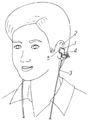
図1乃至図8において、1はイヤホン本体で、イヤホン本体1は、電気音響変換素子(図示せず)を内蔵し、耳介2の凹部(図示せず)に装着された状態で耳介2の一部により支持されるように形成されている。
また、3は、イヤホン本体1に内蔵された前記電気音響変換素子に信号を供給する接続コードである。
また、4は、接続コード3を耳介2の耳珠5と対珠10(図2参照)の間の下方に導出する接続コード導出部である。
DESCRIPTION OF EMBODIMENTS An earphone accessory and an earphone according to an embodiment of the present invention will be described with reference to the drawings.
1 to 8, reference numeral 1 denotes an earphone main body. The earphone main body 1 includes an electroacoustic transducer (not shown) and is attached to a concave portion (not shown) of the
また、6はクリップで、クリップ6は、支軸6aを介して相互に回動可能に連結され、支軸6aより基端側(一端側)に一対の把持部6bを、支軸6aより先端側(他端側)に一対の挟持部6cを、それぞれ有している。一対の挟持部6bは、弾性部材20(例えば、バネである。)により挟持されるものである。
また、7は、クリップ6の一対の把持部6bに取り付けられたアクセサリーである。 そして、イヤホンの接続コード導出部4に一対の挟持部6cを介してクリップ6を取り付けることができるようになっている。
なお、イヤホン用アクセサリーは、クリップ6にアクセサリー7(例えば、編んだビーズ)を取り付けたもので、該イヤホン用アクセサリーは、アクセサリー7を取り付けたクリップ6を一対の挟持部6cを介して接続コード導出部4に取り付けることができるものである。
なお、イヤホンを使用しないときは、接続コード導出部4からクリップ6を外し、例えば、図9に示すように、イヤホンの接続コード3を複数本を結束する結束部材として利用することができるし、また、図示しないが、髪、服等に直接、取り付けるようにしても良い。
The earphone accessory is obtained by attaching an accessory 7 (for example, knitted beads) to the
When the earphone is not used, the
従って、上述したイヤホン用アクセサリー(イヤホン)によれば、イヤホンにアクセサリー7を取り付けることができるため、イヤホンに装飾的な効果を付加することができ、また、アクセサリー7を取り付けられたクリップ6の一対の挟持部6cでイヤホンの接続コード導出部4を挟持するため、イヤホンの接続用コード3等を傷付けることを防ぐことができる。
Therefore, according to the earphone accessory (earphone) described above, since the
また、上述した実施例においては、クリップ6、アクセサリー7を個々に形成したが、本願考案にあってはこれに限らず、図10及び図11に示すように、クリップ6自体に装飾が施されて、クリッ6がアクセサリーとして利用することができるようにしても良い。例えば、クリッ6自体を、蝶の形態(一対の把持部6bを一対の翅に装飾した形態)に したアクセサリーである。
この実施例のイヤホン用アクセサリー(イヤホン)においても、上述の実施例と同様、イヤホンのアクセサリーとして利用することができるクリップ6を取り付けることができるため、イヤホンに装飾的な効果を付加することができ、また、アクセサリーとして利用することができるクリップ6の一対の挟持部6cでイヤホンの接続コード導出部4を挟持するため、イヤホンの接続用コード3等を傷付けることを防ぐことができる。
In the embodiment described above, the
Also in the earphone accessory (earphone) of this embodiment, the
4 …接続コード導出部
6 …クリップ
6a …支軸
6b …把持部
6c …挟持部
7 …アクセサリー
4 ... Connection cord lead-out
Claims (4)
このクリップに取り付けられたアクセサリーとを有し、
前記一対の挟持部は、弾性部材により挟持されるものであり、
前記クリップが前記一対の挟持部を介して耳穴に装着して使用する前記イヤホンの接続コード導出部に取り付けることができる
ことを特徴とするイヤホン用アクセサリー。 A clip that is rotatably connected to each other via a support shaft, and has a pair of gripping portions on the proximal end side from the support shaft and a pair of clamping portions on the distal end side from the support shaft,
With accessories attached to this clip,
The pair of sandwiching portions are sandwiched by elastic members,
The earphone accessory, wherein the clip can be attached to a connection cord lead-out portion of the earphone that is used by being attached to an ear hole via the pair of sandwiching portions.
前記電気音響変換素子に信号を供給する接続コードと、
この接続コードを前記耳介の耳珠と対珠の間の下方に導出する接続コード導出部と、
支軸を介して相互に回動可能に連結され、前記支軸より基端側に一対の把持部を、前記支軸より先端側に一対の挟持部を、それぞれ有するクリップと、
このクリップに取り付けられたアクセサリーとを有し、
前記一対の挟持部は、弾性部材により挟持されるものであり、前記クリップが前記一対の挟持部を介して前記イヤホンの接続コード導出部に取り付けられている
ことを特徴とするイヤホン。 An earphone main body containing an electroacoustic conversion element and formed to be supported by a part of the auricle in a state of being mounted in a concave portion of the auricle;
A connection cord for supplying a signal to the electroacoustic transducer;
A connection cord deriving portion for deriving this connection cord downward between the tragus and the rosicle of the auricle,
A clip that is rotatably connected to each other via a support shaft, and has a pair of gripping portions on the proximal end side from the support shaft and a pair of clamping portions on the distal end side from the support shaft,
With accessories attached to this clip,
The pair of sandwiching portions are sandwiched by an elastic member, and the clip is attached to a connection cord lead-out portion of the earphone via the pair of sandwiching portions.
このクリップ自体に装飾が施されて、前記クリップがアクセサリーとして利用することができるものであり、
前記一対の挟持部は、弾性部材により挟持されるものであり、
前記クリップが前記一対の挟持部を介して耳穴に装着して使用する前記イヤホンの接続コード導出部に取り付けることができる
ことを特徴とするイヤホン用アクセサリー。 A clip that is rotatably connected to each other via a support shaft, and has a pair of gripping portions on the proximal end side from the support shaft and a pair of clamping portions on the distal end side from the support shaft,
The clip itself is decorated, and the clip can be used as an accessory.
The pair of sandwiching portions are sandwiched by elastic members,
The earphone accessory, wherein the clip can be attached to a connection cord lead-out portion of the earphone that is used by being attached to an ear hole via the pair of sandwiching portions.
前記電気音響変換素子に信号を供給する接続コードと、
この接続コードを前記耳介の耳珠と対珠の間の下方に導出する接続コード導出部と、
支軸を介して相互に回動可能に連結され、前記支軸より基端側に一対の把持部を、前記支軸より先端側に一対の挟持部を、それぞれ有するクリップとを有し、
このクリップ自体に装飾が施されて、前記クリップがアクセサリーとして利用することができるものであり、
前記一対の挟持部は、弾性部材により挟持されるものであり、
前記クリップが前記一対の挟持部を介して前記イヤホンの接続コード導出部に取り付けられている
ことを特徴とするイヤホン。 An earphone main body containing an electroacoustic conversion element and formed to be supported by a part of the auricle in a state of being mounted in a concave portion of the auricle;
A connection cord for supplying a signal to the electroacoustic transducer;
A connection cord deriving portion for deriving this connection cord downward between the tragus and the rosicle of the auricle,
A clip that is coupled to each other via a support shaft, and that has a pair of gripping portions on the proximal end side from the support shaft, and a pair of clamping portions on the distal end side from the support shaft,
The clip itself is decorated, and the clip can be used as an accessory.
The pair of sandwiching portions are sandwiched by elastic members,
The earphone, wherein the clip is attached to a connection cord lead-out portion of the earphone via the pair of sandwiching portions.
Priority Applications (1)
| Application Number | Priority Date | Filing Date | Title |
|---|---|---|---|
| JP2009001814U JP3151027U (en) | 2009-03-26 | 2009-03-26 | Earphone accessories and earphones |
Applications Claiming Priority (1)
| Application Number | Priority Date | Filing Date | Title |
|---|---|---|---|
| JP2009001814U JP3151027U (en) | 2009-03-26 | 2009-03-26 | Earphone accessories and earphones |
Publications (1)
| Publication Number | Publication Date |
|---|---|
| JP3151027U true JP3151027U (en) | 2009-06-04 |
Family
ID=54855458
Family Applications (1)
| Application Number | Title | Priority Date | Filing Date |
|---|---|---|---|
| JP2009001814U Expired - Lifetime JP3151027U (en) | 2009-03-26 | 2009-03-26 | Earphone accessories and earphones |
Country Status (1)
| Country | Link |
|---|---|
| JP (1) | JP3151027U (en) |
Cited By (1)
| Publication number | Priority date | Publication date | Assignee | Title |
|---|---|---|---|---|
| JP5457601B1 (en) * | 2013-10-31 | 2014-04-02 | 剛康 村上 | Strap-based earphone entanglement prevention device |
-
2009
- 2009-03-26 JP JP2009001814U patent/JP3151027U/en not_active Expired - Lifetime
Cited By (1)
| Publication number | Priority date | Publication date | Assignee | Title |
|---|---|---|---|---|
| JP5457601B1 (en) * | 2013-10-31 | 2014-04-02 | 剛康 村上 | Strap-based earphone entanglement prevention device |
Similar Documents
| Publication | Publication Date | Title |
|---|---|---|
| US7869615B2 (en) | Sound-box type earphone housing, headset with sound-box type earphone housings | |
| WO2009116272A1 (en) | Bone conduction speaker and listening device using same | |
| TWI465125B (en) | Headset noise reduction | |
| TW448700B (en) | Stereo transducer apparatus | |
| ATE324762T1 (en) | HEADPHONES | |
| TWM316594U (en) | Bluetooth earphone and ear-hook device thereof | |
| TW201626813A (en) | Headset clamping device and headset assembly having the same | |
| CN110958517B (en) | Line card closes piece and possesses earphone of this line card closes piece | |
| EP1969897B1 (en) | Headphones with detachable headband | |
| JP2011019124A (en) | Headphone device | |
| KR20050052099A (en) | Wireless earring type earphone | |
| JP3151027U (en) | Earphone accessories and earphones | |
| CN101203058A (en) | Blue tooth earphone with draw-out type ear suspension | |
| JP3143081U (en) | Glasses wearing earphone | |
| KR100703324B1 (en) | Under the ear wearable earset | |
| JP2012015690A (en) | Headphones | |
| CN201063826Y (en) | Hanging type earplug machine with microphone | |
| CN213880210U (en) | Soft rubber earphone with decoration | |
| JP3157884U (en) | Ear hook | |
| JP4894024B2 (en) | Headphone ear hook attachment structure | |
| CN201015221Y (en) | Audio device for individual | |
| WO2015020387A1 (en) | Earring-type earphone holder | |
| US8194909B2 (en) | Earphone, headset and ear protector | |
| JP2016072946A (en) | earphone | |
| JP3143713U (en) | Headphone ornaments |
Legal Events
| Date | Code | Title | Description |
|---|---|---|---|
| R150 | Certificate of patent or registration of utility model |
Free format text: JAPANESE INTERMEDIATE CODE: R150 |
|
| FPAY | Renewal fee payment (event date is renewal date of database) |
Free format text: PAYMENT UNTIL: 20120513 Year of fee payment: 3 |
|
| R150 | Certificate of patent or registration of utility model |
Free format text: JAPANESE INTERMEDIATE CODE: R150 |
|
| FPAY | Renewal fee payment (event date is renewal date of database) |
Free format text: PAYMENT UNTIL: 20120513 Year of fee payment: 3 |
|
| FPAY | Renewal fee payment (event date is renewal date of database) |
Free format text: PAYMENT UNTIL: 20120513 Year of fee payment: 3 |
|
| FPAY | Renewal fee payment (event date is renewal date of database) |
Free format text: PAYMENT UNTIL: 20130513 Year of fee payment: 4 |
|
| FPAY | Renewal fee payment (event date is renewal date of database) |
Free format text: PAYMENT UNTIL: 20130513 Year of fee payment: 4 |
|
| R250 | Receipt of annual fees |
Free format text: JAPANESE INTERMEDIATE CODE: R250 |
|
| R250 | Receipt of annual fees |
Free format text: JAPANESE INTERMEDIATE CODE: R250 |
|
| R250 | Receipt of annual fees |
Free format text: JAPANESE INTERMEDIATE CODE: R250 |
|
| R250 | Receipt of annual fees |
Free format text: JAPANESE INTERMEDIATE CODE: R250 |
|
| R250 | Receipt of annual fees |
Free format text: JAPANESE INTERMEDIATE CODE: R250 |
|
| EXPY | Cancellation because of completion of term |