JP3148564U - Lighting device - Google Patents
Lighting device Download PDFInfo
- Publication number
- JP3148564U JP3148564U JP2008008547U JP2008008547U JP3148564U JP 3148564 U JP3148564 U JP 3148564U JP 2008008547 U JP2008008547 U JP 2008008547U JP 2008008547 U JP2008008547 U JP 2008008547U JP 3148564 U JP3148564 U JP 3148564U
- Authority
- JP
- Japan
- Prior art keywords
- lighting device
- reflector
- fluorescent lamp
- reflecting plate
- ballast
- Prior art date
- Legal status (The legal status is an assumption and is not a legal conclusion. Google has not performed a legal analysis and makes no representation as to the accuracy of the status listed.)
- Expired - Fee Related
Links
Images
Landscapes
- Securing Globes, Refractors, Reflectors Or The Like (AREA)
- Non-Portable Lighting Devices Or Systems Thereof (AREA)
Abstract
【課題】既存照明装置本体の規格によらず、反射板のみの交換で照明装置の交換を完了することができる照明装置の汎用性および実用性を向上することである。【解決手段】直管蛍光ランプ20の光を反射する反射板2と、反射板2の両端側に設けられ直管蛍光ランプ20の両端を支持するとともに直管蛍光ランプ20に電力を供給する少なくも一対のソケット5と、反射板2の背面側に設けられ直管蛍光ランプ20を点灯させる安定器4と、安定器4と電源コードとを接続可能な端子3とを備えた照明装置において、反射板2の四隅側のそれぞれに螺子が挿通可能な長孔6を設けた。【選択図】 図2An object of the present invention is to improve the versatility and practicality of an illuminating device capable of completing the replacement of the illuminating device by exchanging only the reflection plate, regardless of the standard of the existing illuminating device main body. A reflector 2 that reflects light from a straight tube fluorescent lamp 20 and supports both ends of the straight tube fluorescent lamp 20 provided at both ends of the reflector 2 and supplies power to the straight tube fluorescent lamp 20 are reduced. A lighting device including a pair of sockets 5, a ballast 4 provided on the back side of the reflecting plate 2 for lighting the straight tube fluorescent lamp 20, and a terminal 3 to which the ballast 4 and the power cord can be connected. A long hole 6 through which a screw can be inserted is provided at each of the four corners of the reflecting plate 2. [Selection] Figure 2
Description
この考案は、天井等の壁側部材に設置される照明装置に関する。 The present invention relates to a lighting device installed on a wall-side member such as a ceiling.
従来、天井等の壁側部材に設置される照明装置にあっては、たとえば、図8に示されるように、蛍光ランプの両端を支持するソケットSと直管蛍光ランプKを点灯させる安定器Cとを備え天井Rの開口部に埋め込んで取り付けられる箱型の照明装置本体Lと、直管蛍光ランプKの光を反射する反射板Mとを備えて構成されており、反射板Mは、照明装置本体Lの四隅に設けた螺子孔H1に符合する四箇所に螺子Bが挿通される孔H2を備え、この孔H2に挿通される螺子によって照明装置本体Lの内方に取り付けるようになっている(特許文献1)。
したがって、従来では、照明装置の交換を行う場合、まず、直管蛍光ランプKをソケットSから取り外し、四箇所の螺子Bを取り除いて照明装置本体Lから反射板Mを取り除き、安定器Cと電源コードDとの接続を断ち、古い照明装置本体Lを天井Rの開口部から取り除く。その後、新しい照明装置本体Lを天井Rの開口部に取り付け、安定器Cと電源コードDとを接続するべく配線し直し、反射板Mを照明装置本体Lの内方に固定し、直管蛍光ランプKをソケットSに取り付けて、交換手順が完了することになる。
このように、照明装置の交換は、従来では非常に手間と時間がかかり、作業者は天井側、すなわち、上を向いたままの姿勢で交換作業が強いられることから交換作業は重労働であった。
また、照明装置の寿命の関係から、大規模な建築物では、交換対象の照明装置が多数となることもあり、このような場合、上記交換作業に費やされる時間と手間は莫大となることから、交換作業効率の向上が強く望まれていた。
そこで、このような要望に答えるために、照明装置本体にソケット、安定器を設けるのではなく、反射板にソケットと安定器とを取り付けておき、さらに、照明装置本体と反射板に安定器と電源とを接続可能な雄雌の端子を設けるとともに、反射板と照明装置本体に特別な固定手段を設けてワンタッチで反射板を照明装置本体の内方に固定することが可能な照明装置の提案がなされるに到っている(特許文献2)。
この提案では、上記のように、反射板を照明装置本体の内方に固定手段で固定するときに、反射板は照明装置本体側に設けた案内部材に案内されて、上記雄雌の端子が必ず接続されるようになっており、照明装置の交換は、反射板のみで済み、簡単に反射板を照明装置本体に固定することができる。
Therefore, conventionally, when replacing the lighting device, first, the straight tube fluorescent lamp K is removed from the socket S, the four screws B are removed, the reflector M is removed from the lighting device main body L, and the ballast C and the power source are removed. The connection with the cord D is cut off, and the old lighting device main body L is removed from the opening of the ceiling R. After that, a new illuminating device main body L is attached to the opening of the ceiling R, re-wired to connect the ballast C and the power cord D, the reflector M is fixed to the inside of the illuminating device main body L, and the straight tube fluorescence The lamp K is attached to the socket S, and the replacement procedure is completed.
As described above, the replacement of the lighting device is conventionally labor intensive and time-consuming, and the replacement work is heavy labor because the operator is forced to perform the replacement work with the posture facing the ceiling side, that is, facing upward. .
In addition, due to the life of the lighting device, there may be a large number of lighting devices to be replaced in a large-scale building. In such a case, the time and labor spent on the replacement work are enormous. Therefore, improvement of the replacement work efficiency has been strongly desired.
Therefore, in order to respond to such a demand, a socket and a ballast are not attached to the lighting device body, but a socket and a ballast are attached to the reflecting plate, and further, a ballast is provided to the lighting device body and the reflecting plate. Proposal of an illuminating device that provides male and female terminals that can be connected to a power supply and that can be fixed to the inside of the illuminating device body with one touch by providing a special fixing means on the reflecting plate and the illuminating device body (Patent Document 2).
In this proposal, as described above, when the reflecting plate is fixed to the inside of the lighting device main body by the fixing means, the reflecting plate is guided by the guide member provided on the lighting device main body side, and the male and female terminals are connected. The lighting device is always connected, and the lighting device can be replaced only by the reflecting plate, and the reflecting plate can be easily fixed to the lighting device body.
しかし、上記提案の照明装置にあっては、簡単に照明装置の交換が可能となるが、以下の弊害がある。
すなわち、上記提案では、反射板のみの交換を前提として、反射板と照明装置本体のそれぞれが特別な構造を採用している。このことから、実際に照明装置の交換の際に、反射板のみを交換しようとしても、照明装置本体側が上記提案にあるような反射板に対応していなければ、該交換作業を簡単かつスムーズに行うことができず、反射板の交換を行い得ない場合もある。
つまり、既に天井等に設置済みで古くなったり故障したりしてリニューアルが必要な既存の照明装置本体に雄端子が無い場合には、反射板の安定器に接続されている雌端子を電源に接続することができず、結果的に、該雄雌端子を取外して配線し直す等の作業が必要となり、また、反射板と照明装置本体に取り付けるにあたっても、照明装置本体が反射板側の固定手段に対応していない場合には、反射板の交換が不能となる恐れがあるのである。
したがって、上記提案では、反射板も照明装置本体も専用品であるので、照明装置本体が反射板に対応していない場合には、やはり、従来の照明装置と同様に、照明装置本体の交換を強いられることになり、汎用性に乏しく、実用性にかける点があるのである。
そこで、本考案は、上記した不具合を改善するために創案されたものであって、既存照明装置本体の規格によらず、反射板のみの交換で照明装置の交換を完了することができる照明装置の汎用性および実用性を向上することである。
However, in the proposed lighting device, the lighting device can be easily replaced, but has the following disadvantages.
That is, in the above proposal, each of the reflector and the lighting device main body adopts a special structure on the assumption that only the reflector is replaced. For this reason, even when only replacing the reflector when actually replacing the illumination device, if the illumination device body does not support the reflector as proposed above, the replacement operation can be performed easily and smoothly. In some cases, the reflector cannot be replaced.
In other words, if there is no male terminal in the existing lighting device body that has already been installed on the ceiling or the like and needs to be renewed, the female terminal connected to the ballast of the reflector is used as the power source. As a result, work such as removing and rewiring the male and female terminals is necessary, and also when attaching to the reflector and the illuminator body, the illuminator body is fixed on the reflector side. If it does not correspond to the means, the reflector may not be exchanged.
Therefore, in the above proposal, since the reflector and the lighting device main body are dedicated products, if the lighting device main body does not support the reflecting plate, the lighting device main body should be replaced as in the conventional lighting device. It will be forced, it is poor in versatility, there is a point to put to practical use.
Therefore, the present invention was devised in order to improve the above-described problems, and the lighting device that can complete the replacement of the lighting device by replacing only the reflecting plate, regardless of the standard of the existing lighting device body. It is to improve the versatility and practicality.
上記した目的を達成するために、本考案の課題解決手段は、直管蛍光ランプの光を反射する反射板と、反射板の両端側に設けられ直管蛍光ランプの両端を支持するとともに直管蛍光ランプに電力を供給する少なくも一対のソケットと、反射板の背面側に設けられ直管蛍光ランプを点灯させる安定器と、安定器と電源コードとを接続可能な端子とを備えた照明装置であって、反射板の四隅側のそれぞれに螺子が挿通可能な長孔を設けたことを特徴とする。 In order to achieve the above object, the problem-solving means of the present invention includes a reflector that reflects light from a straight tube fluorescent lamp, and supports both ends of the straight tube fluorescent lamp provided at both ends of the reflector and a straight tube. Illumination device comprising at least a pair of sockets for supplying power to the fluorescent lamp, a ballast provided on the back side of the reflector for lighting the straight tube fluorescent lamp, and a terminal capable of connecting the ballast and the power cord And the elongate hole which can insert a screw in each of the four corner side of a reflecting plate was provided.
本考案の照明装置によれば、反射板の四隅側のそれぞれに螺子が挿通可能な長孔を設けているので、故障やリニューアルが必要な元々天井等に設置済みである規格の異なる種々の既存照明装置本体へ照明装置を取付けることが可能となり、照明装置の汎用性および実用性が向上する。
そして、異なる規格の既存照明装置本体が混在するような建築物における既設の照明装置のリニューアルを行う際にも、同一の照明装置を用意しておけばよいことになるので、作業者がいちいち既存照明装置本体の規格を間近で確認してから、それに適合する照明装置を選び、リニューアル作業を行うといった煩雑な作業を強いられることも回避され、さらには、複数の規格に対応するために異なる照明装置を生産しなくてはならないといった不具合も解消される。
According to the lighting device of the present invention, long holes through which screws can be inserted are provided at each of the four corners of the reflector, so that various existing standards with different standards that are already installed on the ceiling or the like that require failure or renewal are installed. The lighting device can be attached to the lighting device body, and the versatility and practicality of the lighting device are improved.
And when renewing an existing lighting device in a building where existing lighting device bodies of different standards coexist, it is only necessary to prepare the same lighting device, so that an operator already exists. It is also possible to avoid the complicated work of checking the standard of the lighting device body up close, selecting the appropriate lighting device, and performing the renewal work, and different lighting to support multiple standards. The problem of having to produce the device is also eliminated.
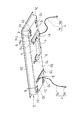
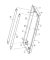
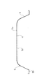
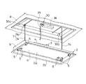
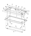
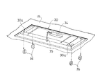
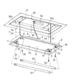
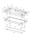
以下に、図示した実施の形態に基づいて、この本考案を説明する。図1は、一実施の形態における照明装置の背面側斜視図である。図2は、一実施の形態における照明装置の反射面側斜視図である。図3は、反射板の断面図である。図4は、照明装置を壁側部材から吊下げた状態を示す図である。図5は、リニューアルが必要な既存照明装置本体から反射板を取り除く手順を示す図である。図6は、リニューアルが必要な既存照明装置本体からソケットを取り除くとともに電源コードを切断する手順を示す図である。図7は、一実施の形態における照明装置をリニューアルが必要な既存照明装置本体に取付ける手順を示す図である。 The present invention will be described below based on the illustrated embodiment. FIG. 1 is a rear perspective view of a lighting device according to an embodiment. FIG. 2 is a perspective view of the reflecting surface side of the lighting device according to the embodiment. FIG. 3 is a cross-sectional view of the reflector. FIG. 4 is a diagram illustrating a state in which the lighting device is suspended from the wall-side member. FIG. 5 is a diagram illustrating a procedure for removing a reflector from an existing lighting device body that needs to be renewed. FIG. 6 is a diagram illustrating a procedure for removing a socket from an existing lighting device body that needs renewal and cutting a power cord. FIG. 7 is a diagram illustrating a procedure of attaching the lighting device according to the embodiment to an existing lighting device body that needs to be renewed.
一実施の形態における照明装置1は、図1および図2に示すように、直管蛍光ランプ20の光を反射する反射板2と、反射板2の両端側に設けられ直管蛍光ランプ20の両端を支持するとともに直管蛍光ランプ20に電力を供給する二対のソケット5と、反射板2の背面側に設けられ直管蛍光ランプ20を点灯させる安定器4と、安定器4と外部電源から伸びる電源コードとを接続する端子3と、反射板2の四隅側のそれぞれに螺子が挿通可能な長孔6と、反射板2を壁側部材から吊り下げることが可能な吊下手段7,7と、を備えて構成されている。
As shown in FIGS. 1 and 2, the illuminating device 1 in one embodiment includes a
以下、各部について詳しく説明する。
図1、図2および図3に示すように、反射板2は、頂部aと、頂部aの四辺から延びて頂部aの四方を囲む側部bとを備えて反射面2a側が開口された断面略台形状の細長の箱型に形成され、また、頂部aと側部bとは湾曲面で連なり、側部bの外周にはフランジ状の縁部2bが設けられている。なお、上記した反射板2の形状は、これに限定されるものではなく、他の形状とすることもできる。
Hereinafter, each part will be described in detail.
As shown in FIGS. 1, 2, and 3, the
そして、反射板2の頂部aにおける長手方向の両端部には、それぞれ短手方向に並べて二つ、すなわち、両端で合計四つの切欠孔2cが開口され、一端側の切欠孔2cと他端側の切欠孔2cとは互いに対向する位置に開口されている。
And in the both ends of the longitudinal direction in the top part a of the
この切欠孔2cには、それぞれ、ソケット5とソケット5を支持するL字状の金具10が反射板2の背面2d側から挿通され、上記金具10は、反射板2にリベット止め等によって固定され、これによって四つのソケット5が反射板2の反射面2a側に突出するように取付けられている。
An L-
そして、反射板2の長手方向で対向するソケット5同士で直管蛍光ランプ20の両端を支持することができるとともに、該直管蛍光ランプ20の両端に設けられる電極に通電することができるようになっている。なお、ソケット5は、上述のように直管蛍光ランプ20の端部を支持でき通電可能なものであれば、どのような形式のものでも採用可能である。
Then, both ends of the straight tube
したがって、直管蛍光ランプ20は、反射板2の内方、すなわち、反射面2a側に設置され、反射面2aで直管蛍光ランプ20の光を照らしたい箇所へ効率よく反射することができるようになっている。
Therefore, the straight tube
さらに、反射板2の頂部aの四隅側のそれぞれには、螺子が挿通可能な長孔6が二つずつ並列されて全体で合計八箇所に設けられており、具体的には、これら長孔6は長手方向に対向するソケット5が設けられる位置より内側となる位置であって、また、それぞれ直管蛍光ランプ20の軸方向に垂直をなす方向に向けて開口されている。
Furthermore, two
続いて、図1に示すように、反射板2の頂部aにおける背面2dには、安定器4が一対のブラケット11,12を介して取付けられており、安定器4は、各ソケット5に電力供給用のコード(図示せず)を介して電力供給することが可能であって、ソケット5によって支持される直管蛍光ランプ20を点灯することができるようになっている。
Subsequently, as shown in FIG. 1, a
なお、安定器4は、本稿では広義に解釈しており、直管蛍光ランプ20に流れる電流を制御し、直管蛍光ランプ20の点灯に必要な始動電圧と各電極に適正な余熱電圧を供給できるものであり、ラピッドスタート型やインバータ型といった種々の形式のものを作用することが可能である。
The
また、上記一対のブラケット11,12は、ともに、反射板2の頂部aの背面2dにスポット溶接等で溶接接合される底部11a,12aと、底部11a,12aから立ち上がる立上部11b,12bと、立上部11b,12bから水平に延びる水平部11c,12cと、を備えて構成され、反射板2の背面2dの一端側と中央側の互いに対向する位置に固定され、安定器4は、各ブラケット11,12の水平部11c,12cに架け渡されるようにして螺子止め等によって固定されている。
The pair of
したがって、安定器4は、上記各ブラケット11,12によって反射板2の背面2d側に固定されているので、安定器4と反射板2の背面2dとの間には、ブラケット11,12の立上部11b,12bの高さ分の隙間が生じて、空間が設けられるようになっている。
Therefore, since the
上記のように、この照明装置1にあっては、安定器4と反射板2との間に空間が設けられているので、安定器4が動作中に発生する熱を外気に効率的に放熱することが可能となっている。
As described above, in this lighting device 1, since the space is provided between the
また、安定器4は、反射板2に溶接によって固定されるブラケット11,12を介して該反射板2に取付けられているので、安定器4を固定する螺子等が反射板2の反射面2a側に突出することが防止されており、これにより、照明装置1の美観が損なわれることがないとともに、直管蛍光ランプ20の光を効率よく反射することが可能となっている。
Further, since the
さらに、上記した各ブラケット11,12のうち、反射板2の中央側に固定されているブラケット12の水平部12cには、端子3が設けられており、この端子3は、外部電源から伸びる2本の電源コードと、アース用コードとに接続可能であるとともに、安定器4にコード(図示省略)で接続され、この端子3を介して安定器4に外部電源から電力供給を行うことができるようになっている。
Further, of the
また、反射板2の背面2dの他端に、上記ブラケット11と同形状のブラケット13がスポット溶接等によって溶接接合されており、このブラケット13と、上記した各ブラケット11,12のうち、反射板2の一端側に固定されているブラケット11の水平部11cには、それぞれ、弦部材たるワイヤ14の一端が連結され、このワイヤ14の他端には、取付手段たるフック15が設けられている。
A
上記取付手段たるフック15は、図4に示すように、故障やリニューアルが必要な元々天井R等に設置済みであった反射板を取り除いた壁側部材となる既存照明装置本体30へワイヤ14を着脱自在に取付けることが可能であり、既存照明装置本体30のフック15を引っ掛けることが可能な箇所に当該フック15を引っ掛けることによって、壁側部材たる既存照明装置本体30から各フック15とワイヤ14とで反射板2を吊下げることができるようになっている。
As shown in FIG. 4, the
したがって、本実施の形態においては、上記一対のワイヤ14とフック15とで吊下手段が構成されていることになる。なお、取付手段としては、上記フック15以外にも、ワイヤ14を既存照明装置本体30に着脱自在に取付けることができるものであればよく、取付手段には螺子や他の金具を採用することも可能であるが、フック15は既存照明装置本体30へ引っ掛ける簡単な作業で反射板2を吊下げることができ便利である。また、上記フック15は、いわゆるナスカンフックとされており、上記既存照明装置本体30へ引っ掛けると、ロックされて脱落することが無いようになっている。
Therefore, in the present embodiment, the hanging means is constituted by the pair of
そして、上記各ワイヤ14のブラケット11,13への連結位置は、反射板2の対角線上となる部位とされている。これにより、反射板2を既存照明装置本体30から吊下げても、反射板2が極端に傾くような事態が防止されている。
And the connection position of each said
なお、弦部材としては、フレキシブルで照明装置1の総重量によって破断しない充分な強度を備えているものであればよく、上記したワイヤ14の他に、たとえば、チェーンやロープ、紐等を用いることができる。
The string member may be any member that is flexible and has sufficient strength not to be broken by the total weight of the lighting device 1. For example, a chain, rope, string, or the like is used in addition to the
また、安定器4を支持する一方のブラケット11と、ワイヤ14が連結されるブラケット13を同一形状として部品形状が統一されているので、生産性が向上し、製造コストも低減されることになる。
Moreover, since one
さて、上述のように構成された照明装置1は、以下に示すような手順で、天井Rに設置されている既存照明装置本体30に取付けることができる。
Now, the illuminating device 1 comprised as mentioned above can be attached to the existing illuminating device
まず、交換対象の照明装置である既存照明装置本体30から、図5に示すように、直管蛍光ランプ31を取り除き、さらに、反射板32の四隅を貫き既存照明装置本体30の螺子孔30aに捩じ込まれている螺子33を緩めて取り払って、反射板32を既存照明装置本体30から取り除く。
First, as shown in FIG. 5, the straight
続いて、図6に示すように、既存照明装置本体30の安定器34に電力供給している電源コード35を下方に引き出し、任意の箇所にて切断するとともに、既存照明装置本体30に備え付けのソケット36を、ソケット36と安定器34とを接続している図示しないコードを切断してから該既存照明装置本体30から取り除く。
Subsequently, as shown in FIG. 6, the
その後、図4に示すように、各フック15を既存照明装置本体30の適宜の箇所に引っ掛けて照明装置1を吊下げ、その状態を保って、電源コード35を端子5に接続する。このとき、上記した弦部材たるワイヤ14の長さは、照明装置1を吊下げた状態で脚立等に乗って作業を行っている作業者が充分に反射板2の背面2dを見下ろすことができるような長さに設定されており、上記した電源コード35を端子3に接続する作業を行う際には、作業者は、上方を見上げるような作業負担が重くなりがちな体勢を強いられることがないので、作業負担が軽減され、また、手元を楽に確認しながら作業を行えるので作業効率も向上することになる。
After that, as shown in FIG. 4, the
さらに、上述のように、上記各ワイヤ14のブラケット11,13への連結位置は、反射板2の対角線上となる部位とされて、反射板2を既存照明装置本体30から吊下げても、反射板2が極端に傾くような事態が防止されている。
Further, as described above, the connection position of each
したがって、反射板2が作業者側と反対方向に大きく傾いてしまって、わざわざ作業者が脚立から降り、脚立をずらして、再度脚立に乗って反射板2の反対側に回り込むことを強いられたり、電源コード35を端子3に接続する危険を伴う作業を行う際に、反射板2の傾きの補正を強いられたりといった煩わしさがなく、作業負担が軽減されるとともに、作業性の向上および作業員の安全性が確保されることになる。
Therefore, the
引き続き、上述の状態から、図7に示すように、反射板2を既存照明装置本体30の内方へ挿入し、反射板2に設けた各長孔6のうち螺子孔33の位置と一致する四箇所の長孔6に螺子33を挿入するとともに、該螺子33を螺子孔30aに捩じ込んで反射板2を既存照明装置本体30に螺子止めする。すなわち、古い既存照明装置本体30はそのまま嵌め殺しとなり、新たな照明装置1を天井R等に固定する役割を果たすのみとなる。
Subsequently, from the above-described state, as shown in FIG. 7, the
また、上記した反射板2には縁部2bが設けられているので、既存照明装置本体30の枠を縁部2bで覆い隠すことができ、さらには、照明装置1の外周周りのサイズが既存照明装置本体30のそれより多少小さい場合に合っても、照明装置1の外周と既存照明装置本体30の枠との間に隙間を生じさせることがないので、リニューアル後の照明装置1回りの美観を損ねることが防止されている。
Moreover, since the
そして、上述のように、照明装置1を従前に使用されていた既存照明装置本体30に取付けるために螺子33が挿通される孔が長孔6とされており、既存照明装置本体30の螺子孔30aの位置に長孔6の一部が一致すれば、照明装置1を既存照明装置本体30に取付けることが可能とであるから、規格の異なる種々の既存照明装置本体30へ同一の照明装置1を取付けることが可能となり、照明装置1の汎用性および実用性が向上する。
And as above-mentioned, the hole through which the
そして、異なる規格の既存照明装置本体30が混在するような建築物における既設の照明装置のリニューアルを行う際にも、同一の照明装置1を用意しておけばよいことになるので、作業者がいちいち既存照明装置本体30の企画を間近で確認してから、それに適合する照明装置を選び、リニューアル作業を行うといった煩雑な作業を強いられることも回避され、さらには、複数の規格に対応するために異なる照明装置を生産しなくてはならないといった不具合も解消される。
And when renewing the existing illuminating device in a building where existing illuminating device
したがって、長孔6は、反射板2の四隅のそれぞれに一つずつの全体で合計四つ設けるようにしてもよいが、本実施の形態のように、二つずつ並列に設けておくことによって、より多くの異なる規格の既存照明装置本体30に対応することが可能となり、照明装置1の汎用性および実用性がより一層向上し、また、上記したリニューアル作業の煩雑化をより一層回避可能であり、生産の点でも有利となる。なお、並列される長孔6の数を、ふやせばより多くの規格に対応可能なことはいうまでもない。
Therefore, a total of four
また、既存照明装置本体30の螺子孔30aの位置は、既存照明装置本体30の直管蛍光ランプ31に真上に設けられることが多いことから、長孔6を直管蛍光ランプ20の軸方向に対し垂直に向く方向に設けることによって、既存照明装置本体30の直管蛍光ランプの間隔および搭載本数と、照明装置1の直管蛍光ランプ20の間隔や搭載本数とが異なっても、照明装置1を取付けられる可能性が大きくなり有利となる。
Further, since the position of the
したがって、反射板2の四隅のそれぞれに複数の長孔6を直管蛍光ランプ20の軸方向に対し垂直に向く方向に設けて並列させると、照明装置1を効果的に既存照明装置本体30のより多くの規格に対応させることが可能となるのである。
Therefore, when the plurality of
最後に、ソケット5,5に直管蛍光ランプ20を装着して、照明装置のリニューアルが完了する。
Finally, the straight
なお、取付手段たるフック14は既存照明装置本体30に取付けたままとしておいてあり、何らかの理由で、螺子33が緩んで抜けてしまい、照明装置1が既存照明装置本体30から抜けてしまうようなことがあっても、照明装置1は上記吊下手段7,7で吊下げられて床に落下してしまうことがないので、照明装置1の安全性、信頼性が向上する。
Note that the
以上で、本考案の実施の形態についての説明を終えるが、本考案の範囲は図示されまたは説明された詳細そのものには限定されないことは勿論である。 This is the end of the description of the embodiments of the present invention, but the scope of the present invention is of course not limited to the details shown or described.
1 照明装置
2 反射板
3 端子
4 安定器
5 ソケット
6 長孔
7 吊下手段
2a 反射面
2b 縁部
2c 切欠孔
2d 背面
10 金具
11,12,13 ブラケット
11a,12a 底部
11b,12b 立上部
11c,12c 水平部
14 弦部材たるワイヤ
15 取付手段たるフック
20 直管蛍光ランプ
30 壁側部材となる既存照明装置本体
a 頂部
b 側部
DESCRIPTION OF SYMBOLS 1
Claims (6)
反射板の両端側に設けられ直管蛍光ランプの両端を支持するとともに直管蛍光ランプに電力を供給する少なくも一対のソケットと、
反射板の背面側に設けられ直管蛍光ランプを点灯させる安定器と、
安定器と電源コードとを接続可能な端子とを備えた照明装置であって、
前記反射板の四隅側のそれぞれに螺子が挿通可能な長孔を設けたことを特徴とする照明装置。 A reflector that reflects the light of the straight tube fluorescent lamp;
At least a pair of sockets provided on both ends of the reflector to support both ends of the straight fluorescent lamp and to supply power to the straight fluorescent lamp;
A ballast that is provided on the back side of the reflector and lights a straight tube fluorescent lamp;
A lighting device comprising a terminal capable of connecting a ballast and a power cord,
An illuminating device characterized in that a long hole through which a screw can be inserted is provided at each of the four corners of the reflecting plate.
一対の弦部材の一端は、反射板の対角線上となる部位に連結されることを特徴とする請求項4に記載の照明装置。 The suspension means includes a pair of string members having one end connected to the back side of the reflector, and an attachment means that is provided at the other end of the string member and removably attaches the string member to the wall side member,
The lighting device according to claim 4, wherein one end of the pair of string members is connected to a portion on a diagonal line of the reflecting plate.
Priority Applications (1)
| Application Number | Priority Date | Filing Date | Title |
|---|---|---|---|
| JP2008008547U JP3148564U (en) | 2008-12-05 | 2008-12-05 | Lighting device |
Applications Claiming Priority (1)
| Application Number | Priority Date | Filing Date | Title |
|---|---|---|---|
| JP2008008547U JP3148564U (en) | 2008-12-05 | 2008-12-05 | Lighting device |
Related Parent Applications (1)
| Application Number | Title | Priority Date | Filing Date |
|---|---|---|---|
| JP2005352717A Continuation JP2007157557A (en) | 2005-12-06 | 2005-12-06 | Lighting device |
Publications (1)
| Publication Number | Publication Date |
|---|---|
| JP3148564U true JP3148564U (en) | 2009-02-19 |
Family
ID=54782106
Family Applications (1)
| Application Number | Title | Priority Date | Filing Date |
|---|---|---|---|
| JP2008008547U Expired - Fee Related JP3148564U (en) | 2008-12-05 | 2008-12-05 | Lighting device |
Country Status (1)
| Country | Link |
|---|---|
| JP (1) | JP3148564U (en) |
-
2008
- 2008-12-05 JP JP2008008547U patent/JP3148564U/en not_active Expired - Fee Related
Similar Documents
| Publication | Publication Date | Title |
|---|---|---|
| US7080923B2 (en) | Surface mount fluorescent strip light fixture retrofit kit and method | |
| KR20160110696A (en) | Flat light | |
| US6494601B2 (en) | Modular cluster lighting fixture | |
| US10527232B2 (en) | LED bulb adapters and methods of retrofitting LED bulbs | |
| JP2008251482A (en) | Lighting device housing | |
| US20020136001A1 (en) | Low-profile fluorescent luminaire and methods of installation | |
| JP2007157557A (en) | Lighting device | |
| JP2013120672A (en) | Illumination system for straight tube led lamp | |
| KR200456726Y1 (en) | Lamp apparatus for lighting | |
| JP5146892B1 (en) | Straight tube lamp case | |
| CN206890298U (en) | A kind of fast-assembling ceiling lamp of easy-to-connect | |
| CN201391807Y (en) | Main keel lamp with accessory box | |
| KR101644269B1 (en) | An apparatus for mounting lighting | |
| JP6960213B2 (en) | How to replace straight tube fluorescent lamps with LED lamps and lighting fixtures for LED lamps | |
| KR200475930Y1 (en) | Down lighting lamp apparatus for reclaiming | |
| KR200372953Y1 (en) | A lighting assembly | |
| CN210107203U (en) | Ceiling lamp convenient to change lamps and lanterns | |
| JP5797810B1 (en) | Cable holder for lighting case | |
| JP4051809B2 (en) | lighting equipment | |
| CN201344424Y (en) | Ceiling lamp | |
| JP2010129208A (en) | Pole type lighting fixture | |
| JPS6230244Y2 (en) | ||
| JP3849556B2 (en) | Recessed lighting fixture | |
| JP5042802B2 (en) | Lighting device and lighting system | |
| US11236891B1 (en) | Fixture folding hook |
Legal Events
| Date | Code | Title | Description |
|---|---|---|---|
| R150 | Certificate of patent or registration of utility model |
Free format text: JAPANESE INTERMEDIATE CODE: R150 |
|
| FPAY | Renewal fee payment (event date is renewal date of database) |
Free format text: PAYMENT UNTIL: 20120128 Year of fee payment: 3 |
|
| FPAY | Renewal fee payment (event date is renewal date of database) |
Free format text: PAYMENT UNTIL: 20120128 Year of fee payment: 3 |
|
| FPAY | Renewal fee payment (event date is renewal date of database) |
Free format text: PAYMENT UNTIL: 20150128 Year of fee payment: 6 |
|
| LAPS | Cancellation because of no payment of annual fees |