JP3147736U - Pointer-type pressure gauge and charge measuring device composed thereof - Google Patents
Pointer-type pressure gauge and charge measuring device composed thereof Download PDFInfo
- Publication number
- JP3147736U JP3147736U JP2008007614U JP2008007614U JP3147736U JP 3147736 U JP3147736 U JP 3147736U JP 2008007614 U JP2008007614 U JP 2008007614U JP 2008007614 U JP2008007614 U JP 2008007614U JP 3147736 U JP3147736 U JP 3147736U
- Authority
- JP
- Japan
- Prior art keywords
- pointer
- pressure
- pressure gauge
- passage
- charging
- Prior art date
- Legal status (The legal status is an assumption and is not a legal conclusion. Google has not performed a legal analysis and makes no representation as to the accuracy of the status listed.)
- Expired - Lifetime
Links
- 230000000149 penetrating Effects 0.000 claims abstract description 4
- 210000000515 Tooth Anatomy 0.000 claims description 20
- 238000005259 measurement Methods 0.000 claims description 16
- 230000005540 biological transmission Effects 0.000 claims description 12
- 230000004807 localization Effects 0.000 claims description 11
- 230000000875 corresponding Effects 0.000 claims description 5
- 239000003921 oil Substances 0.000 claims description 5
- 230000002093 peripheral Effects 0.000 claims description 5
- 239000010687 lubricating oil Substances 0.000 claims description 3
- 238000005096 rolling process Methods 0.000 description 7
- 238000007789 sealing Methods 0.000 description 7
- 238000009530 blood pressure measurement Methods 0.000 description 6
- 230000001808 coupling Effects 0.000 description 6
- 238000010168 coupling process Methods 0.000 description 6
- 238000005859 coupling reaction Methods 0.000 description 6
- 239000007787 solid Substances 0.000 description 3
- 230000003796 beauty Effects 0.000 description 2
- 238000007872 degassing Methods 0.000 description 2
- 238000010586 diagram Methods 0.000 description 2
- 230000035515 penetration Effects 0.000 description 2
- 230000003068 static Effects 0.000 description 2
- 230000005483 Hooke's law Effects 0.000 description 1
- 210000000214 Mouth Anatomy 0.000 description 1
- 238000006073 displacement reaction Methods 0.000 description 1
- 230000003203 everyday Effects 0.000 description 1
- 238000005461 lubrication Methods 0.000 description 1
- 230000004048 modification Effects 0.000 description 1
- 238000006011 modification reaction Methods 0.000 description 1
- 230000035945 sensitivity Effects 0.000 description 1
- 238000000926 separation method Methods 0.000 description 1
Images


Abstract
【課題】指針式圧力計及びそれにより組成された充気測定器の提供。
【解決手段】圧力計本体と、指針部材と、圧力調整部材とを含む指針式圧力計において、前記圧力計本体は、貫通道を備えており、前記指針部材は、前記圧力計本体に組み合わせ、それに前記貫通道と相通しており、前記圧力調整部材は、前記貫通道に設置されて、しかも、調節チューブと、弾性部品と、調節操作部材を含む。標準圧力値の気体が前記貫通道に注がれる時、前記気体は、前記調節チューブを駆動してそれに前記弾性部品を圧縮して、前記調節チューブが前記指針部材を駆動させて、測定圧力値を表示しており、前記測定圧力値が、当該の標準気圧値と一致しない時に、前記調節操作部材が、前記弾性部品の伸縮を調整することに使われて、それによって、当該測定圧力値を校正する。前記指針式圧力計は、充気部材と結合する時、充気測定器を組合せて、それによって、充気気体の充気圧力値を表示する。
【選択図】図1An object of the present invention is to provide a pointer-type pressure gauge and a charge measuring device composed thereof.
In a pointer-type pressure gauge including a pressure gauge body, a pointer member, and a pressure adjustment member, the pressure gauge body includes a through passage, and the pointer member is combined with the pressure gauge body. In addition, the pressure adjusting member is installed in the penetrating path and includes an adjusting tube, an elastic part, and an adjusting operating member. When a gas of standard pressure value is poured into the through-passage, the gas drives the adjustment tube and compresses the elastic part thereto, and the adjustment tube drives the pointer member to measure the pressure value. When the measured pressure value does not match the standard atmospheric pressure value, the adjustment operating member is used to adjust the expansion and contraction of the elastic part, thereby the measured pressure value is Calibrate. When the pointer-type pressure gauge is combined with the charging member, it combines the charging measuring device, thereby displaying the charging pressure value of the charging gas.
[Selection] Figure 1
Description
本考案は、指針式圧力計及びそれにより組成された充気測定器に関し、特に、測定圧力値を校正できる指針式圧力計及びそれにより組成された充気測定器に関するものである。 The present invention relates to a pointer-type pressure gauge and a charge measuring device composed thereof, and more particularly to a pointer-type pressure gauge capable of calibrating a measured pressure value and a charge measuring device composed thereof.
日常生活において、圧力計は、通常はインフレ物の気圧を測るのに使われる。たとえば、タイヤ内部のタイヤ圧力及びバスケットボールの内部圧力等を測るのに使われる。現有の圧力計は、指針式圧力計とデジタル式圧力計を主流としている。その中、デジタル式圧力計は、高い敏感度と高い精確度等の美点を備えているが、その構造が精密な電子装置であるため、一般的に、価格が高くて、震動に耐えないで、保養しにくくて、及び電源を使用しなければならない等の欠点がある。 In everyday life, pressure gauges are usually used to measure the pressure of inflation. For example, it is used to measure the tire pressure inside the tire and the internal pressure of basketball. The existing pressure gauges are mainly pointer-type pressure gauges and digital pressure gauges. Among them, the digital pressure gauge has beauty such as high sensitivity and high accuracy, but its structure is a precise electronic device, so it is generally expensive and cannot withstand vibration. However, there are drawbacks such as difficulty in recuperating and having to use a power source.
比べれば、指針式圧力計は、その構造が簡単で、震動に耐えて、電源をつけなくても使用できること等の美点を備えって、今まで相変わらず社会大衆から歓迎を受けてある。大体の指針式圧力計は、ほとんどスプリングの弾力と気体圧力の間の平衡原理を利用して、フック法則(Hooke’s law:弾力=バネ定数×変位バネののびは、それに加えられた力に比例する)の応用を合わせて、それによって、指針を駆動させて測定圧力値を表示する。 In comparison, the pointer-type pressure gauge has received the welcome from the public as before, with the beauty of being simple in structure, resistant to vibration and being usable without turning on the power supply. Most pointer-type pressure gauges use the principle of balance between spring elasticity and gas pressure, and the Hooke's law (elasticity = spring constant x displacement spring expansion is proportional to the force applied to it. ), Thereby driving the pointer and displaying the measured pressure value.
また、実務運用の上で、所定の測定範囲内に測った測定圧力値は、いっそう精確となれる。例えば、指針式圧力計の最大測定範囲(即ち、目盛板に表示された測定範囲である)は、0〜200psiであって、一般的に、最初で使用している時、大体中央1/3の測定範囲(即ち65〜135psiの測定範囲である)内で測った測定圧力値は、いっそうに精密で精確となる。しかし、スプリングの弾力が失い始めてくることに従い、だんだんと大体後面1/3の測定範囲(即ち135〜200psiの測定範囲である)内で図った測定圧力値は、いっそうに精密で精確となる。 Moreover, the measured pressure value measured within a predetermined measurement range can be made more accurate in practical operation. For example, the maximum measurement range of a pointer-type pressure gauge (that is, the measurement range indicated on the dial plate) is 0 to 200 psi, and is generally about 1/3 of the center when first used. The measured pressure value measured within the measuring range (ie, the measuring range of 65 to 135 psi) becomes more precise and accurate. However, as the spring's elasticity begins to lose, the measured pressure value within the measuring range of about 1/3 of the rear surface (that is, the measuring range of 135 to 200 psi) becomes more precise and accurate.
指針式圧力計は、長期に使用されていた後、いったんスプリングの弾力が失ってしまって、また、スプリングの弾性係数もついてに変動しており、同時に、おのおの連結部品は、緩くなってまたはがたがたの現象を起こして、それによって、測った測定圧力値を影響してしまう。従って、いったんより小さい圧力を測る時に、測った測定圧力値は、実際の圧力値と大きな誤差を生じている。 The pointer-type pressure gauge, after being used for a long period of time, once lost its spring elasticity and fluctuated with the elastic modulus of the spring, and at the same time, each connecting part became loose or rattled This causes the measured pressure value to be affected. Therefore, once a smaller pressure is measured, the measured pressure value has a large error from the actual pressure value.
およそ所属技術領域の中で、通常知識を持つ専門者にとって、従来の指針式圧力計は、静態なゼロ点調整機能と動態な圧力調整機能を欠いているように知られる。従って、初期化のゼロ点調整を行うことができない。即ち、少数の指針式圧力計は、ゼロ点調整の回転ボタンを設置しても、指針式圧力計のみに対して静態なゼロ点調整を行って、異なる測定範囲による圧力測定標的に対応して適当な動態圧力調整を行うことができない。従って、本考案の考案者は、指針式圧力計に係る結構の改良を必要として、それに動態な圧力調整の機能を備えさせることを深く感じている。 In the technical field of which the profession belongs, it is known to the expert with ordinary knowledge that the conventional pointer-type pressure gauge lacks a static zero-point adjustment function and a dynamic pressure adjustment function. Therefore, the zero point adjustment for initialization cannot be performed. In other words, a small number of pointer-type pressure gauges can perform zero-point adjustment statically only for the pointer-type pressure gauges, even if a zero-point adjustment rotary button is installed, to support pressure measurement targets with different measurement ranges. Appropriate dynamic pressure adjustment cannot be performed. Therefore, the inventor of the present invention deeply feels that it requires a considerable improvement of the pointer-type pressure gauge and has a dynamic pressure adjustment function.
上述によって、従来の指針式圧力計において、一般的に動態な圧力調整機能を欠いているため、指針式圧力計が、長く使い続けられたら、スプリングの弾力性が失われて、そしておのおの連結部品は、緩くなってまたはがたがたの現象を発生して、それによって、測った測定圧力値を影響してしまう。更に、多くの圧力測定標的の落差が大きくなって、しかもそれぞれ異なった測定範囲に当たる時、動態な圧力調整を行って精確な測定圧力値を測ることができない。 As described above, since the conventional pressure gauges generally lack a dynamic pressure adjustment function, if the pointer pressure gauges are used for a long time, the elasticity of the springs is lost, and each connecting part Causes a loose or rattling phenomenon, thereby affecting the measured pressure value. Furthermore, when the drop of many pressure measurement targets becomes large and each falls in a different measurement range, it is impossible to accurately measure the pressure value by performing dynamic pressure adjustment.
従って、本考案の主な目的は、指針式圧力計を提供して、当該指針式圧力計の圧力計本体内に貫通道を開設しており、それに直接に圧力調整部材を貫通道の一端に設置させて、しかも指針部材と圧力調整部材を連動させており、それによって、圧力調整部材で動態圧力の校正を行う。 Therefore, the main object of the present invention is to provide a pointer-type pressure gauge and to establish a through passage in the main body of the pointer-type pressure gauge, and to directly attach a pressure adjusting member to one end of the through-passage. In addition, the pointer member and the pressure adjusting member are interlocked, and the dynamic pressure is calibrated by the pressure adjusting member.
本考案は、従来の技術問題を解決するために、指針式圧力計を提供して、前記指針式圧力計は、圧力計本体と、指針部材と、圧力調整部材を含む。前記圧力計本体は、貫通道を備えており、前記指針部材は、前記圧力計本体に組み合わされて、それに前記貫通道と相通しており、前記圧力調整部材は、前記貫通道に設置されて、しかも、調節チューブと、弾性部品と、調節操作部材を含む。標準圧力値を有する気体が前記貫通道に入り込む時、前記気体は、前記調節チューブを駆動させて前記弾性部品を圧縮して、それによって前記調節チューブが前記指針部材を駆動させて、測定圧力値を表示しており、前記測定圧力値が、当該標準の気圧値と一致しない時に、前記調節操作部材は、前記弾性部品を伸縮するに用いられて、それによって動態的に当該測定圧力値を校正する。前記指針式圧力計は充気部材と結合する時、充気測定器を構成して、それは、充気気体の充気圧力値を表示する。 The present invention provides a pointer-type pressure gauge in order to solve the conventional technical problems, and the pointer-type pressure gauge includes a pressure gauge body, a pointer member, and a pressure adjusting member. The pressure gauge main body includes a through passage, the pointer member is combined with the pressure gauge main body and communicates with the through passage, and the pressure adjusting member is installed in the through passage. In addition, an adjustment tube, an elastic part, and an adjustment operation member are included. When a gas having a standard pressure value enters the through-passage, the gas drives the adjustment tube to compress the elastic part, thereby causing the adjustment tube to drive the pointer member to measure the pressure value. When the measured pressure value does not match the standard atmospheric pressure value, the adjustment operation member is used to expand and contract the elastic part, thereby dynamically calibrating the measured pressure value. To do. When the pointer-type pressure gauge is combined with the charge member, it constitutes a charge measurement device, which displays the charge pressure value of the charge gas.
本考案の好ましい実施例によれば、圧力調整部材は、更にゼロ点調整部材を含み、前記ゼロ点調整部材は、貫通道の一端に設置されて、しかも気体が前記貫通道に入れる前に調整チューブと連動しており、それによって、気体が前記貫通道に入れる前に指針部材が表示した測定圧力値をゼロ点にさせる。 According to a preferred embodiment of the present invention, the pressure adjusting member further includes a zero point adjusting member, and the zero point adjusting member is installed at one end of the through passage and is adjusted before gas enters the through passage. In conjunction with the tube, the measured pressure value displayed by the pointer member before the gas enters the through passage is brought to the zero point.
従来の技術に係る指針式圧力計と比べれば、本考案に係る指針式圧力は、前記指針式圧力計の圧力計本体内に貫通道を開設しており、直接に圧力調整部材を貫通道の一端に設置させてある。従って、標準圧力値を有する気体が前記貫通道に入り込む時、測定圧力値が測られていて、前記測った測定圧力値が、当該標準の気圧値と一致しない時に、前記圧力調整部材と前記指針部材との連動を介して、動態的に前記測定圧力値を校正することができる。 Compared with the pointer-type pressure gauge according to the prior art, the pointer-type pressure according to the present invention has a penetrating path in the pressure gauge body of the pointer-type pressure gauge, and the pressure adjusting member is directly connected to the penetrating pressure gauge. It is installed at one end. Therefore, when a gas having a standard pressure value enters the through-passage, a measured pressure value is measured, and when the measured pressure value does not match the standard atmospheric pressure value, the pressure adjusting member and the pointer The measured pressure value can be calibrated dynamically through interlocking with the member.
上述から明らかに分かって、本考案に係る指針式圧力計は、異なる測定範囲に当たる多種な圧力測定標的に対して圧力測定を行う前に、適当に動態な圧力校正を行うことができ、従って、本考案に係る指針式圧力計は確かに十分に精確な測定圧力値を測ることができる。 As can be clearly seen from the above, the pointer-type pressure gauge according to the present invention can appropriately perform dynamic pressure calibration before performing pressure measurement on various pressure measurement targets in different measurement ranges. The pointer-type pressure gauge according to the present invention can surely measure the measured pressure value sufficiently accurately.
以下、本考案の実施の形態を図面に基づいて説明する。
本考案に係る指針式圧力計及びそれにより組成された充気測定器は、広範に圧力範囲に使用されており、特にタイヤの圧力測定に適用されて、その組合の実施方式は、枚挙にいとまがないため、後でくどくど述べなく、茲では一つの好ましい実施例だけで具体的に説明します。
Hereinafter, embodiments of the present invention will be described with reference to the drawings.
The pointer-type pressure gauge according to the present invention and the charge measuring device composed thereby are widely used in the pressure range, and are particularly applied to the measurement of tire pressure. Because there is no shortage, I will explain in detail later only in one preferred embodiment.
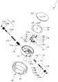
図1及び図2を参照する。図1は、本考案の好ましい実施例に係る指針式圧力計の立体分解図を示す。図2は、本考案の好ましい実施例に係る指針式圧力計が組み立てた後の立体外観図を示す。図1に示すように、指針式圧力計は、圧力計本体11、指針部材12、圧力調整部材13、受圧部材14、空気フィルター部材15、定位部材16、限位部品17、圧力目盛板18、封装部材19を含む。
Please refer to FIG. 1 and FIG. FIG. 1 shows a three-dimensional exploded view of a pointer-type pressure gauge according to a preferred embodiment of the present invention. FIG. 2 shows a three-dimensional external view after the pointer type pressure gauge according to a preferred embodiment of the present invention is assembled. As shown in FIG. 1, the pointer type pressure gauge includes a pressure gauge main body 11, a pointer member 12, a pressure adjustment member 13, a
前記圧力計本体11は、入気口111、周面112と貫通道113を備える。前記貫通道113は、周面112を貫通しており、それに入気口111を連通する。指針部材12は、固定座121、指針駆動部品122、指針123、二つのねじ124、125を含む。指針駆動部品122は、複数の伝動歯122aを備えて、前記複数の伝動歯122aは、圧力計本体11の中心と結合して、しかも前記貫通道113と連通しており、指針123は、指針駆動部品122を結合しており、固定座121は、ねじ124、125で前記圧力計本体11に結合しており、それによって、指針駆動部品122を固定する。
The pressure gauge main body 11 includes an
前記圧力調整部材13は、調節チューブ131、弾性部品132、調節操作部材133とゼロ点調整部材134を含む。前記調節チューブ131は、前記貫通道113に嵌め込まれており、前記調節チューブ131の表面に複数の凸環131aが突き出されて、しかも少なくとも前記複数の伝動歯122a中の一つは、少なくとも前記複数の凸環131a中の一つと係止する。弾性部品132は、調節チューブ131と相互に連結して、本実施例に、弾性部品132は、螺旋ばね(helical spring)であって、しかも調節チューブ131内に設置される。
The pressure adjustment member 13 includes an
調節操作部材133は、圧力調節桿133a、螺管133b、ナット133cを含む。圧力調節桿133aは、弾性部品132と連結しており、本実施例において、圧力調節桿133aの一端は、螺旋ばね(helical spring)の中心に差し入れて、そしてそれと連結して、圧力調節桿133aの他の一端は、螺管133bの中心に貫通して、ナット133cで螺管133bと相互に結合して係止する。螺管133bは、貫通道113に螺合して、圧力調整部材13を貫通道113の一端に結合させる。
The adjusting
ゼロ点調整部材134は、ゼロ点調整桿134aと、ワッシャー134bと、弾性環134cと、螺管134dと、ナット134eを含む。受圧部材14は、受圧片141と弾性環142を含む。受圧片141は、調節チューブ131に接触する。弾性環142は、受圧片141の周面に固着して、それに貫通道113の壁面としっかり接触する。同時に、受圧部材14の受圧片141に更に、油タンク141aを開設して、前記油タンク141aは、潤滑油を貯蔵して、しかもゼロ点調整桿134aと、受圧片141と、貫通道113の壁面に潤滑機能を提供する。
The zero
ゼロ点調整桿134aは、受圧部材14の受圧片141に接触して、順序にワッシャー134bと、弾性環134cと、螺管134dを貫通して、しかもナット134eに螺合して、それによって、ワッシャー134bと、弾性環134cと、螺管134dをゼロ点調整桿134aに固着させる。その上、ワッシャー134bは、貫通道113の壁面としっかり接触しており、螺管134dは、貫通道113に螺合して、圧力調整部材13を貫通道113の一端に結合することができる。
The zero
空気フィルター部材15は、固定環151、フィルター152を含み、前記固定環151は、圧力計本体11に結合しており、前記フィルター152は、前記固定環151に設置されてある。定位部材16は、定位板161、ワッシャー162、ねじ163を含み、しかも前記ねじ163は、ワッシャー162を貫通して、定位板161を圧力計本体11に固着させる。本実施例では、前記定位板161は、扇形のアウトライン構造であって、前記扇形のアウトライン構造の扇縁の処に、複数の定位歯161aを有して、前記扇形のアウトライン構造の扇柄の処は、ワッシャー162とねじ163で圧力計本体11に固着してある。少なくとも一つの前記複数の定位歯161aは、少なくとも一つの前記伝動歯122aと相互に係止して、それによって、指針駆動部品122が駆動された時、定位部材16の定位板161は、前記ねじ163で中心として回転させて、しかも同期に予定な位置に駆動されてある。
The
限位部品17は、定位部材16の定位板161と相互に結合しており、前述の所定位置と前記指針駆動部品122による有効な作用範囲に対して制限する。圧力目盛板18は、圧力計本体11と結合して、しかも複数の圧力目盛181を付けてある。前記指針123は、圧力目盛板18に置かれてある。封装部材19は、封装ハウジング191と、透明蓋体192を含み、前記封装ハウジング191は、圧力計本体11を容置するのに使われて、透明蓋体192は、封装ハウジング191と結合して、それに圧力目盛板18をかぶせる。
The
入気口111を介してすべての気体を貫通道113に入れない前に、使用者は、ゼロ点調整部材134のゼロ点調整桿134aを操作できて、それに静態のゼロ点校正作業を行うことができる。使用者が、ゼロ点調整部材134のゼロ点調整桿134aを操作できる時、受圧片141を調節チューブ131に押し詰めさせて、それに調節チューブ131を弾性部品132へ向かせて動いて、或いは、弾性部品132を調節チューブ131に押し詰めさせて、それに調節チューブ131を受圧片141へ向かせて動いてある。調節チューブ131の凸環131aで指針駆動部品122の伝動歯122aを駆動させて、それに、指針123を上述した複数の圧力目盛181のゼロ点に表示させることを制御できる。従って、指針部材12の指針123が表示した測定圧力値をゼロ点にさせる。
The user can operate the zero
アクティブストレインゲージASGは、標準圧力値の気体G1を提供しており、しかも前記気体G1が、入気口111を通って貫通道113に入れられる時、弾性部品132は、弾力を提供して、気体G1による圧力は、受圧片141に対して気体推力を提供して、弾性部品132からの弾力と受圧片141から受けた気体推力は、平衡に達する時、調節チューブ131を駆動して対応する位置に移動させて、それに指針駆動部品122を作動して、指針123を前記複数の圧力目盛181の間に回転させて、それによって、測定した圧力値を表示できる。
The active strain gauge ASG provides a gas G1 having a standard pressure value, and when the gas G1 enters the through passage 113 through the
測定した圧力値が、標準気圧値と一致しない時、使用者は、圧力調節桿133aを操作できて、それに弾性部品132の伸縮量を制御してある。所属の技術領域においてすべての普通の知識を持つ者が理解できて、弾性部品132が異なる伸縮量によって相対応する弾性を提供する。従って、弾性部品132の伸縮量を調整する同時に、弾性部品132に提供された弾性を調整する。それによって、圧力調節桿133aで前記調整弾性部品132の伸縮量を調整する時、指針123が前記複数の圧力目盛181の間に回転して表示した測定の圧力値も調整できて、測定した圧力値が標準圧力値と一致している時、動態な圧力校正を完成できる。
When the measured pressure value does not coincide with the standard atmospheric pressure value, the user can operate the
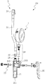
次に、図3及び図4を参照する。図3は、本考案の好ましい実施例に係る充気部材と充気管部が分解された後、指針式圧力計との相対応する位置の関係図を示す。図4は、本考案の好ましい実施例に係る指針圧力計、充気部材と充気管部が組み合わされて充気測定器となった立体の立体外観図を示す。同時に、図1を並びに参照してください。図3及び図4に示すように、充気部材2と充気管部3、前記の指針式圧力計1は、充気測定器100に組合うことができる。
Reference is now made to FIGS. FIG. 3 is a relationship diagram of corresponding positions of the pointer type pressure gauge after the charging member and the charging pipe portion according to a preferred embodiment of the present invention are disassembled. FIG. 4 shows a three-dimensional external view of a solid pressure gauge, a charging member, and a charging pipe unit according to a preferred embodiment of the present invention. At the same time, please refer to Figure 1 as well. As shown in FIGS. 3 and 4, the charging
充気部材2は、充気ハンドル21、充気押板22、押板結合部材23、測定連結部材24と出気連結部材25を含む。充気ハンドル21は、充気入口211、充気出口212、分気口213を含む。充気入口211は、充気源ISを連通する。充気出口212は、充気入口211を連通しており、分気口213は、充気入口211を連通する。
The
充気押板22は、押板結合部材23を介して充気ハンドル21に接合する。押板結合部材23は、螺旋スプリング、連結シャフト、防気漏洩のワッシャー、バルブ、充気圧力調整部品とナット等の部品を含む。測定連結部材24は、連結管、防気漏洩のワッシャー、フィルター等の部品を含み、それに指針式圧力計1及び充気ハンドル21を相互に連結して、それによって、分気口213と入気口111を相互に連通させる。出気連結部材25は、転接管と防気漏洩のワッシャー等の部品を含み、それに充気管部3及び充気ハンドル21と連結して、充気出口212と充気管部3を相互に連通する。充気管部3は、ゴムパイプ31、入口転接部材32と出気転接部材33と含む。その中、入口転接部材32は、それぞれゴムパイプ31と出気連結部材25を連結しており、出気転接部材33は、ゴムパイプ31を連結する。各部品の間の組合関係は、図3に示される。
The
使用者が、充気押板22を押している時、充気気体G2は、充気源ISから充気入口へ注いで、そして充気気体G2は、充気出口212から出て被充気物IOまで流れており、同時に、充気気体G2は、分気口213と入気口111を通って指針式圧力計1の貫通道113まで転送されてある。また、充気気体G2は、受圧片141で弾性部品132を圧縮させて、そして調節チューブ131を駆動して、それによって調節チューブ131が、指針部材12を駆動させて充気圧力値を表示する。
When the user is pushing the charging
本考案において、指針式圧力計1は、異なる測定範囲による複数の圧力測定標的に対して、圧力測定をする前に、圧力調整部材13のゼロ点調整部材134で予め静態にゼロ点校正をして、更にアクティブストレインゲージASGを利用して、異なる標準気圧値を有する気体G1を提供して、調節操作部材133を操作することで動態に圧力校正を行う。従って、指針式圧力計1が、異なる測定範囲による複数の圧力測定標的に対して、圧力測定をする時、充分で精確な測定圧力値を測定することができる。
In the present invention, the pointer-
上記では、種々の実施の形態および変形例を説明したが、本考案はこれらの内容に限定されるものではない。本考案の技術的思想の範囲内で考えられるその他の態様も本考案の範囲内に含まれる。 Although various embodiments and modifications have been described above, the present invention is not limited to these contents. Other embodiments conceivable within the scope of the technical idea of the present invention are also included in the scope of the present invention.
100 充気測定器
1 指針式圧力計
11 圧力計本体
111 入気口
112 周面
113 貫通道
12 指針部材
121 固定座
122 指針駆動部品
122a 伝動歯
123 指針
124、125 ねじ
13 圧力調整部材
131 調節チューブ
131a 凸環
132 弾性部品
133 調節操作部材
133a 圧力調節桿
133b 螺管
133c ナット
134 ゼロ点調整部材
134a ゼロ点調整桿
134b ワッシャー
134c 弾性環
134d 螺管
134e ナット
14 受圧部材
141 受圧片
141a 油タンク
142 弾性環
15 空気フィルター部材
151 固定環
152 フィルター
16 定位部材
161 定位板
161a 定位歯
162 ワッシャー
163 ねじ
17 限位部品
18 圧力目盛板
181 圧力目盛
19 封装部材
191 封装ハウジング
192 透明蓋体
2 充気部材
21 充気ハンドル
211 充気入口
212 充気出口
213 分気口
22 充気押板
23 押板結合部材
24 測定連結部材
25 出気連結部材
3 充気管部
31 ゴムパイプ
32 入口転接部材
33 出気転接部材
ASG アクティブストレインゲージ
IS 充気源
IO 被充気物
G1 気体
G2 充気気体
DESCRIPTION OF
Claims (21)
前記圧力計本体は、入気口、周面と当該周面を貫通して当該入気口と連通している貫通道を備えて、
前記指針部材は、前記圧力計本体に組み合わせ、前記貫通道と相通しており、
前記圧力調整部材は、前記貫通道の一端に設置されて、しかも、前記貫通道内に嵌め込まれて前記指針部材とお互いに対応する調節チューブと、前記調節チューブとお互いに連結する弾性部品と、前記弾性部品を連結する調節操作部材と、を含み、
標準圧力値を有する気体が前記貫通道に入り込む時、前記気体は、前記調節チューブを駆動して前記弾性部品を圧縮して、前記調節チューブが前記指針部材を駆動させて、測定した圧力値を表示しており、前記測定した圧力値が、当該標準の気圧値と一致しない時に、前記調節操作部材が、前記弾性部品を伸縮することで前記調節チューブを駆動することに用いられて、前記調節チューブが前記指針部材を駆動させて、これによって、動態的に前記測定した圧力値を修正できるようになることを特徴とする指針式圧力計。 In a pointer-type pressure gauge including a pressure gauge body, a pointer member, and a pressure adjustment member,
The main body of the pressure gauge includes an inlet, a peripheral surface, and a through passage that penetrates the peripheral surface and communicates with the inlet.
The pointer member is combined with the pressure gauge body and communicates with the through-passage,
The pressure adjusting member is installed at one end of the through-passage, and is fitted into the through-passage, the adjustment member corresponding to the pointer member and the elastic member connected to the adjustment tube, An adjusting operation member for connecting the elastic parts,
When a gas having a standard pressure value enters the through-passage, the gas drives the adjustment tube to compress the elastic part, and the adjustment tube drives the pointer member to measure the measured pressure value. When the measured pressure value does not match the standard atmospheric pressure value, the adjustment operation member is used to drive the adjustment tube by expanding and contracting the elastic part, and the adjustment A pointer-type pressure gauge, characterized in that a tube drives the pointer member so that the measured pressure value can be corrected dynamically.
前記定位部材は、圧力計本体に固定されて、それに複数な定位歯を有して、少なくとも一つの前記複数の定位歯は、少なくとも一つの前記伝動歯と相互に係止して、それによって、指針駆動部品が駆動された時、同期に予定な位置に駆動されてあって、
前記限位部品は、定位部材と相互に結合しており、前述の所定位置と前記指針駆動部品による有効な作用範囲に対して制限する、
ことを特徴とする、請求項4に記載の指針式圧力計。 Including stereotactic members and confining parts,
The stereotaxic member is fixed to the pressure gauge body and has a plurality of stereotaxic teeth thereon, at least one of the plurality of stereotactic teeth interlocking with at least one of the transmission teeth, thereby When the pointer drive component is driven, it is driven to the expected position in synchronization,
The localization component is mutually coupled to the localization member, and limits the effective range of operation by the predetermined position and the pointer driving component.
The pointer-type pressure gauge according to claim 4, wherein:
前記充気部材は、充気ハンドルと、充気押板を含み、
前記充気ハンドルは、
充気源を連通する充気入口と、
前記充気入口を連通する充気出口と、
前記充気入口及び前記入気口を連通する分気口と、を含み、
前記充気押板は、充気ハンドルに接合しており、
その上、充気押板が押されている時、充気気体が、充気源から充気入口へ注いで、そして前記充気気体が、充気出口から出て、同時に前記充気気体が、分気口と入気口を通って指針式圧力計の貫通道まで転送されて、それに弾性部品を圧縮して、調節チューブを駆動させて、それによって調節チューブが、前記指針部材を駆動させて充気圧力値を表示することを特徴とする充気測定器。 In the charging pressure measuring instrument including the pointer-type pressure gauge according to claim 1 and a charging member,
The charging member includes a charging handle and a charging push plate,
The charging handle is
A charge inlet communicating with the charge source;
An air outlet that communicates with the air inlet;
An air inlet that communicates with the air inlet and the air inlet;
The charging push plate is joined to the charging handle,
Moreover, when the charging push plate is pushed, the charging gas is poured from the charging source to the charging inlet, and the charging gas exits from the charging outlet, and at the same time the charging gas is Transferred through the air inlet and inlet to the penetrating passage of the pointer-type pressure gauge, compressing the elastic parts to drive the adjusting tube, thereby causing the adjusting tube to drive the pointer member A charge measuring device characterized by displaying a charge pressure value.
前記定位部材は、圧力計本体に固定されて、それに複数な定位歯を有して、少なくとも一つの前記複数の定位歯は、少なくとも一つの前記伝動歯と相互に係止して、それによって、指針駆動部品が駆動された時、同期に予定な位置に駆動されてあって、
前記限位部品は、定位部材と相互に結合しており、前述の所定位置と前記指針駆動部品による有効な作用範囲に対して制限することを特徴とする、請求項14に記載の充気測定器。 In addition, it includes a localization member and a localization component,
The stereotaxic member is fixed to the pressure gauge body and has a plurality of stereotaxic teeth thereon, at least one of the plurality of stereotactic teeth interlocking with at least one of the transmission teeth, thereby When the pointer drive component is driven, it is driven to the expected position in synchronization,
15. The charge measurement according to claim 14, wherein the localization component is mutually coupled with a localization member and restricts the effective range of the predetermined position and the pointer driving component. vessel.
Publications (1)
| Publication Number | Publication Date |
|---|---|
| JP3147736U true JP3147736U (en) | 2009-01-15 |
Family
ID=
Similar Documents
| Publication | Publication Date | Title |
|---|---|---|
| US6848292B2 (en) | System for calibration of pressure transducers | |
| US7228743B2 (en) | Light powered pressure gauge | |
| AU2012269184B2 (en) | Pressure indicator | |
| US20100162822A1 (en) | Heating and Air Conditioning Service Gauge | |
| US7685882B1 (en) | Heating and air conditioning service gauge | |
| US3868844A (en) | Dynamic arterial blood pressure simulator | |
| US7441460B2 (en) | Vacuum regulator with two gauges | |
| JP2019191164A (en) | Pressure gage | |
| JP3147736U (en) | Pointer-type pressure gauge and charge measuring device composed thereof | |
| US8733270B2 (en) | Pressure indication device of inflation machine | |
| US4547859A (en) | Methods for scaling and calibrating predetermined signals | |
| US3948103A (en) | Calibration of dialed measuring instruments | |
| US1422485A (en) | Power indicator for internal-combustion engines | |
| CN208223710U (en) | The pressure gauge easily assembled | |
| CN201096555Y (en) | Compensation type digital micro manometer | |
| TWI792525B (en) | Pressure gauge with divisional scale | |
| CN208872459U (en) | A kind of pressure gauge | |
| CN219348038U (en) | Gas pressure measuring instrument | |
| RU2722630C1 (en) | Pneumatic low-pressure source | |
| CN216160065U (en) | Digital differential pressure gauge | |
| CN212275113U (en) | Refrigerant pressure gauge | |
| EP0634185A2 (en) | Digital dual pressure guage | |
| Sharma et al. | Use of strain gauge pressure transducer as working pressure standard up to 500 MPa | |
| CN113701938A (en) | Pressure gauge with different interval scales | |
| JP3807814B2 (en) | Pressure gauge |