JP3143541U - Pushbutton structure with multi-mode display function - Google Patents
Pushbutton structure with multi-mode display function Download PDFInfo
- Publication number
- JP3143541U JP3143541U JP2008003168U JP2008003168U JP3143541U JP 3143541 U JP3143541 U JP 3143541U JP 2008003168 U JP2008003168 U JP 2008003168U JP 2008003168 U JP2008003168 U JP 2008003168U JP 3143541 U JP3143541 U JP 3143541U
- Authority
- JP
- Japan
- Prior art keywords
- light
- emitting element
- button
- layer
- pushbutton
- Prior art date
- Legal status (The legal status is an assumption and is not a legal conclusion. Google has not performed a legal analysis and makes no representation as to the accuracy of the status listed.)
- Expired - Lifetime
Links
Images


Abstract
【課題】同一ボタン位置に異なるボタン画像を表示し、押ボタン実体の操作性を向上することのできるマルチモード表示機能付押ボタン構造を提供する。
【解決手段】複数のボタン位置101を有する押ボタン層10と、前記押ボタン層10の下方に多層状に配置された複数の指示ユニット20とを含み、各指示ユニット20は、発光素子201と、該発光素子201に組み合わさる導光素子202とを有し、前記導光素子202の一方の表面に模様層203が設けられ、前記模様層203は、前記ボタン位置101に対応する複数の模様を有する。
【選択図】図1Provided is a pushbutton structure with a multi-mode display function capable of displaying different button images at the same button position and improving the operability of the pushbutton entity.
A push button layer having a plurality of button positions and a plurality of indication units arranged in a multilayer form below the push button layer. Each indication unit includes a light emitting element and a light emitting element. A light guide element 202 combined with the light emitting element 201, and a pattern layer 203 is provided on one surface of the light guide element 202, and the pattern layer 203 includes a plurality of patterns corresponding to the button positions 101. Have
[Selection] Figure 1
Description
本考案は、マルチモード表示機能付押ボタン構造に係り、特に、同一ボタン位置に異なるボタン画像を表示する押ボタン構造に関する。 The present invention relates to a pushbutton structure with a multi-mode display function, and more particularly to a pushbutton structure that displays different button images at the same button position.
現代社会では科学技術の進歩に伴い、電子情報製品の発展が日々速くなっている。しかしながら、唯一変化のないことは、ユーザが所定の関連するコマンドを入力しなければ、電子製品は、入力されたコマンドに従って演算、対比などの動作を行いかつユーザが得ようとする様々なメッセージ及び情報を出力できないことである。
現在、情報流通の時代であり、無線通信は、人々にとても便利なライフスタイルをもたらしている。例えば、携帯電話、PDA、ノートブック、或いはMP3プレーヤ等の装置は、いずれも、日常生活に使用されている。ユーザは、それらの装置における入力ツールとしてキーボードを用い、電子装置を制御し様々な最新情報を得るのが最も普通に行われている。
In modern society, with the advancement of science and technology, the development of electronic information products is accelerating every day. However, the only change is that if the user does not input a predetermined related command, the electronic product performs various operations such as operation, comparison and the like according to the input command, and various messages and The information cannot be output.
Currently, in the age of information distribution, wireless communication has brought a very convenient lifestyle to people. For example, devices such as mobile phones, PDAs, notebooks, and MP3 players are all used in daily life. It is most common for users to use a keyboard as an input tool in these devices to control electronic devices and obtain various up-to-date information.
しかしながら、近年、電子装置の体積が微小化するに伴い、軽薄外形の製品を構成するが、押ボタンのサイズ、数量も段々と制限されている。MP3プレーヤを例とすると、基本的なMP3の機能はシンプルであり、押ボタンは、基本的に従来のウォークマン(登録商標)の設計を引用している。具体的には、再生/一時停止、早送り、巻き戻し、及び音量調節のボタンがそれぞれ独立して設けられている。 However, in recent years, as the volume of electronic devices has become smaller, products with light and thin outlines are configured, but the size and quantity of pushbuttons are gradually limited. Taking the MP3 player as an example, the basic MP3 functions are simple, and the push buttons basically cite the design of the conventional Walkman (registered trademark). Specifically, buttons for playback / pause, fast forward, rewind, and volume control are provided independently.
しかしながら、個人消費者に対するマルチメディア産業の発展に伴い、FMラジオ、録音、電子ブック、及びピクチャ閲覧など多くの付加機能がプレーヤの設計に持ち込まれている。このため、押ボタンが“足りない”という問題が出始め、ボタン毎に二つの機能(長押し/短押し)を与える手法が多く適用されている。
さらには、5位方向キーというものがあるが、ボタン数を減らす目的は達成できるが、全体の便利性について大きく向上するものではない。
However, with the development of the multimedia industry for individual consumers, many additional functions such as FM radio, recording, electronic book, and picture browsing are brought into the player design. For this reason, the problem of “insufficient” pushbuttons has started to appear, and many techniques for providing two functions (long press / short press) for each button have been applied.
Furthermore, although there is a fifth direction key, the purpose of reducing the number of buttons can be achieved, but the overall convenience is not greatly improved.
そのため、本考案者は、前記のような従来のキーボード構造が実際に使用する時にもたらす欠点に鑑みて、長年この領域で積み立てた経験により、専念な観察かつ研究をし、さらに学術理論の運用に合せ、合理な設計且つ前記の問題点を有効に改良できたマルチモード表示可能なキーボード構造を提案した。 Therefore, in light of the shortcomings of the conventional keyboard structure as described above, the present inventor has made extensive observations and research based on the experience accumulated in this area for many years, and further applied academic theory. In addition, a keyboard structure capable of multi-mode display has been proposed which has a rational design and can effectively improve the above problems.
本考案の主な目的は、同一ボタン位置に異なるボタン画像を表示し、押ボタン実体の操作性を向上することのできるマルチモード表示機能付押ボタン構造を提供することにある。 A main object of the present invention is to provide a pushbutton structure with a multi-mode display function capable of displaying different button images at the same button position and improving the operability of the pushbutton entity.
本考案の次の目的は、押ボタンの置く角度に応じて押ボタンに表示される模様方向を調整し、ユーザがボタン機能を識別する識別度を向上することのできるマルチモード表示機能付押ボタン構造を提供することにある。 The next object of the present invention is to adjust the pattern direction displayed on the push button according to the angle at which the push button is placed, and to improve the degree of identification for the user to identify the button function. To provide a structure.
前記目的を達成するため、本考案は、複数のボタン位置を有する押ボタン層と、前記押ボタン層の下方に多層状に配置された複数の指示ユニットとを含み、前記各指示ユニットは、発光素子と、該発光素子と組み合わさる導光素子とを有し、前記導光素子の一方の表面に模様層が設けられ、前記模様層は、前記ボタン位置に対応する複数の模様を有することを特徴とするマルチモード表示機能付押ボタン構造を提供した。 In order to achieve the above object, the present invention includes a push button layer having a plurality of button positions, and a plurality of instruction units arranged in a multilayer form below the push button layer, wherein each of the instruction units emits light. An element and a light guide element combined with the light emitting element, a pattern layer is provided on one surface of the light guide element, and the pattern layer has a plurality of patterns corresponding to the button positions. A pushbutton structure with multi-mode display function is provided.
また、前記目的を達成するため、本考案は、第1領域ボタン位置及び第2領域ボタン位置にそれぞれ区画される複数のボタン位置を有する押ボタン層と、発光素子及び該発光素子に組み合わさる導光素子を有し、前記導光素子の一方の表面に模様層が設けられ、前記模様層は、これらのボタン位置に対応する複数の模様を有し、前記押ボタン層の下方に配置された第1の指示ユニットと、第1発光素子及び該第1発光素子に組み合わさる第1導光素子を有し、前記第1導光素子の一方の表面に第1模様層が設けられ、前記第1模様層は、前記第1領域ボタン位置に対応する複数の模様を有する第1指示モジュール、及び、第2発光素子及び該第2発光素子に組み合わさる第2導光素子を有し、前記第2導光素子の一方の表面に第2模様層が設けられ、前記第2模様層は、前記第2領域ボタン位置に対応する複数の模様を有する第2指示モジュールを含み、前記第1の指示ユニットの下方に配置された第2の指示ユニットと、含むことを特徴とするマルチモード表示機能付押ボタン構造を提供した。 In order to achieve the above object, the present invention provides a push button layer having a plurality of button positions respectively divided into a first area button position and a second area button position, a light emitting element, and a light emitting element combined with the light emitting element. An optical element is provided, a pattern layer is provided on one surface of the light guide element, the pattern layer has a plurality of patterns corresponding to these button positions, and is disposed below the push button layer A first indicator unit; a first light-emitting element; and a first light-guiding element combined with the first light-emitting element, wherein a first pattern layer is provided on one surface of the first light-guiding element, The one pattern layer includes a first indicator module having a plurality of patterns corresponding to the first region button positions, a second light emitting element, and a second light guide element combined with the second light emitting element. 2 A second pattern layer is provided on one surface of the light guide element. And the second pattern layer includes a second instruction module having a plurality of patterns corresponding to the second region button positions, and a second instruction unit disposed below the first instruction unit. A pushbutton structure with a multi-mode display function is provided.
上記のマルチモード表示機能付押ボタン構造により、多層指示構造で同一ボタン位置に異なる押ボタン画像を表示し、限られている数の押ボタンが制御可能な押ボタン機能を増加する目的を達成することができる。 The above-described pushbutton structure with a multi-mode display function achieves the purpose of increasing the pushbutton function that can control a limited number of pushbuttons by displaying different pushbutton images at the same button position in a multi-layer pointing structure. be able to.
本考案の特徴および技術内容をより詳しく了解するために、以下に本考案に関わる詳細な説明及び添付図面を参照すれば、深くかつ具体的に理解できると確信しているが、それらの添付図面が参考及び説明のみに使われ、本考案の主張範囲を狭義的に局限するものではないことは言うまでもないことである。 In order to understand the features and technical contents of the present invention in more detail, the following detailed description and accompanying drawings relating to the present invention are considered to be deeply and concretely understood. It is needless to say that is used only for reference and explanation and does not narrowly limit the scope of the present invention.
図1に示すように、本考案は、同一ボタン位置に異なる画像を表示し、ユーザに異なる押ボタン機能を与えるマルチモード表示機能付押ボタン構造1であって、その構造は、複数のボタン位置101を有する押ボタン層10と、該押ボタン層10の下方に多層状に配置された複数の指示ユニット20とを含む。
As shown in FIG. 1, the present invention is a
図1に示すマルチモード表示機能付押ボタン構造1は、2つの指示ユニット20を備えるが、これは一例であって、指示ユニット20の数は、本考案を限定するものではない。本実施形態において、該二つの指示ユニット20は類似した構造であり、例えば、二つの指示ユニット20は、ともに、発光素子201と、該発光素子201と組み合わさる導光素子202とを有し、該導光素子202の一方の表面に模様層203が設けられる。さらに、該模様層203には、これらのボタン位置101に対応する複数の指示模様が成形されている。前記二つの指示ユニット20の違いは、図3(A)及び図3(B)に示すように、それらに形成された模様が異なる点である。
The
前記押ボタン層10は、実体押ボタンであり、その上に複数のボタン位置101を有し、ユーザが入力するための押しボタン機能を与えるものである。また、その下方に設けられた指示ユニット20は、ボタン位置101毎に、対応する押しボタン機能の指示画像を表示する。指示ユニット20毎に設けられた発光素子201(例えば、白光LED等)は、前記導光素子202の側辺に設置され、該導光素子202は、発光素子201から発する光を該押ボタン層10の方向へ発射する。
The
前記導光素子202は、輝度や均一度を向上させると共に、拡散率を増加させ、マルチモード表示機能付押ボタン構造1の全体輝度及び視角の品質を向上する。また、該導光素子202の一方の表面には模様層203が設けられ、発光素子201から発する光が、該導光素子202の導光、散光の機能によって、さらに、模様層203を介して押しボタン機能に対応する画像、符号または字母などを形成するようになされている。
The
そのため、使用に際しては、ユーザは、スイッチの設計により、オンしたい指示ユニット20を選び、その押ボタン層10に機能ボタンを表示させる。
さらに、図3A、図3Bに加え、図1を用いて説明する。ユーザがスイッチでダイヤル機能を選択すると、この時、上層に位置される指示ユニット20の発光素子201がオンされて光を発し、該光が導光素子202の導光、屈折、反射などの光学作用を経て、さらに、模様層203を介して押しボタン毎の機能が表示される。
Therefore, at the time of use, the user selects the
Furthermore, in addition to FIG. 3A and FIG. 3B, it demonstrates using FIG. When the user selects the dial function with the switch, at this time, the
図3Aに示すように、該上層の指示ユニット20の模様層203上には数字模様2031を有し、各数字模様2031が押ボタン層10の各ボタン位置101に対応する。そして、ユーザが、それらの数字模様2031の指示によってダイヤルする機能が実現される。
As shown in FIG. 3A, a
同様に、ユーザが音楽機能をオンすると、下層に位置される指示ユニット20の発光素子201がオンされ光を発し、該光が該導光素子202の導光、屈折、及び反射などの光学作用を経て、さらに、模様層203を介して押しボタン毎の機能が表示される。
Similarly, when the user turns on the music function, the
図3Bに示すように、該下層の指示ユニット20の模様層203上には音楽再生模様2031’を有し、各音楽再生模様2031’が該押ボタン層10の各ボタン位置101に対応する。そして、ユーザがこれらの音楽再生模様2031’の指示によって該電子装置が制御され音楽再生の機能が実現される。
また、異なる指示ユニット20の模様層203は、異なる色のカラーインクで形成するのが好ましく、そうすれば異なる色の模様で異なる属性のボタン機能を利用できる。
As shown in FIG. 3B, a
The
一方、押ボタン層10と指示ユニット20との間には、さらに偏光ユニット401を有している。該偏光ユニット401は、偏光板、1/4波長シート、または偏光板と1/4波長シートの組合であればよい。該偏光ユニット401の役割は、押ボタン層10の前方の光、例えば、日ざしなどをフィルティングし、眩光を防ぐ機能を提供し、これらの模様のコントラストを向上させる。
On the other hand, a polarizing
また、隣接する二つの指示ユニット20の間には、さらにラスタユニット501が設けられる。該ラスタユニット501は、ラスタシートまたは偏光板であり、その役割は上下の画像を断絶し、下層模様が表示される時に上層指示ユニット20の構造またはその模様層203の色に影響することを回避する。
また、光源がオンする場合、該ラスタユニット501は、光線を遮断し、外側から内部の模様を見られないようにする。尚、下層の指示模様の表示に影響を与えないように、上層の模様層203が透光性を有するのが好ましい。
Further, a
When the light source is turned on, the
図2に、本考案に係る第2の実施形態を示す。図2に示すように、第1の実施形態との違いは、下層の指示ユニット20’の発光素子201’が、自己発光ユニットであるEL素子(electro luminescence)であり、そのため、発光素子201’は、模様層203の下方に直接設けられる点である。
発光素子201’がオンされ光を発すると、直接的に該模様層203を介してボタン位置101毎に異なる押しボタン機能を表示できる。ここで注意すべきは、これらの指示ユニット20の数は、上記の実施例に制限されることではなく、実際に適用される機能に応じて調整できる。
FIG. 2 shows a second embodiment according to the present invention. As shown in FIG. 2, the difference from the first embodiment is that the light-emitting
When the
一方、本考案は、他の実施態様のマルチモード表示機能付押ボタン構造1を提案し、複数の指示モジュールで異なる領域のボタン位置に対応し、該押ボタン層10のうちの異なる領域のボタン位置101に、異なる指示模様を表示させる。
On the other hand, the present invention proposes a
図4、図5を用いて、本考案に係る第3の実施形態を説明する。図4に示す構造において、図5A、図5Bに示す第1領域ボタン位置101A及び第2領域ボタン位置101Bにそれぞれ区画される複数のボタン位置101を有する押ボタン層10と、発光素子201及び該発光素子201に組み合わさる導光素子202を有する。導光素子202の一方の表面に模様層203が設けられ、該模様層203は、各ボタン位置に対応する複数の模様を有している。
尚、押ボタン層10の下方には、第1の指示ユニット20Aを含むが、該第1の指示ユニット20Aは、第1の実施形態において説明した指示ユニット20の特徴と同じであるため、その説明を省略する。
A third embodiment according to the present invention will be described with reference to FIGS. In the structure shown in FIG. 4, a
In addition, although the 1st instruction |
本実施形態の第1の実施形態との違いは、第1の指示ユニット20Aの下方に配置された第2の指示ユニット30が、第1指示モジュール30A及び第2指示モジュール30Bを含むことである。
以下に、前記両モジュールについて説明する。第1指示モジュール30Aは、第1発光素子301A及び該第1発光素子301Aに組み合わさる第1導光素子302Aを有する。第1導光素子302Aの一方の表面には第1模様層303Aが設けられ、該第1模様層303Aは、該第1領域ボタン位置101Aに対応する複数の模様を有する。
The difference between the present embodiment and the first embodiment is that the
Hereinafter, both the modules will be described. The
第2指示モジュール30Bは、第2発光素子301B及び該第2発光素子301Bに組み合わさる第2導光素子302Bを有する。第2導光素子302Bの一方の表面には第2模様層303Bが設けられ、該第2模様層303Bは、該第2領域ボタン位置101Bに対応する複数の模様を有する。
The
ユーザが第1の指示ユニット20Aをオンすると、該マルチモード表示機能付押ボタン構造1は、図3Aに示された数字模様2031を表示し、各数字模様2031は、該押ボタン層10の各ボタン位置101に対応し、ユーザがこれらの数字模様2031の指示によってダイヤルする機能を実現できる。
また、ユーザが第2の指示ユニット30の第1指示モジュール30Aをオンすると、該第1指示モジュール30Aは、図5Aに示す第1領域ボタン位置101A(上部二行)にマルチメディア制御模様3031Aを表示し、図5(B)に示す第2領域ボタン位置101B(下部二行)にあらゆる模様を表示しない。
When the user turns on the
When the user turns on the
同様に、ユーザが第2の指示ユニット30の第2指示モジュール30Bをオンすると、該第2指示モジュール30Bは、その対応する第2領域ボタン位置101Bに写真制御模様3031Bを表示し、ユーザがこれらの写真制御模様3031Bに従い電子装置を制御し撮影する機能を実現できる。
よって、押ボタン層10は、キーボード装置がより多いボタン機能を有するように、押しボタンをより効率的に配置することができる。
尚、本実施形態では、他の部材、例えば、ラスタユニット501等は、何れも第1の実施形態と同じであるため、その説明を省略する。
Similarly, when the user turns on the
Therefore, the
In the present embodiment, the other members, for example, the
また、本考案に係るマルチモード表示機能付押ボタン構造1は、さらに、例えば、液体スイッチなどの装置を搭載して多機能の設定を行うことができる。
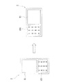
図6に示す携帯電話2は、表示装置21及び本考案のマルチモード表示機能付押ボタン構造1を有する。前記マルチモード表示機能付押ボタン構造1は、直立型押ボタン模様(即ち、第1の実施形態における上部の指示ユニット20)及び横型押ボタン模様(即ち、第1の実施形態における下部の指示ユニット20)が設けられている。
In addition, the
A
携帯電話を直立させた時には、液体表示されるスイッチは、前記上部の指示ユニット20をオンさせ、これらのボタン位置101に直立型押ボタン模様を表示する。一方、該携帯電話2を横型にした時には、液体表示されるスイッチは、前記下部の指示ユニット20をオンさせ、これらのボタン位置101に横型押ボタン模様を表示する。
これにより、ユーザは各ボタン位置101における機能の意義をより明確に識別できるようになる。
When the mobile phone is set upright, the switch displayed in liquid turns on the
As a result, the user can more clearly identify the significance of the function at each
尚、以上説明した応用例は本考案に係るマルチモード表示機構付押ボタンの一形態に過ぎず、これに本考案の応用が限定されるものではない。また、本考案は、携帯電話などの装置に限定されるものではなく、他の実体ボタンを用いる電子装置に広く適用することができる。 The application example described above is merely one form of the pushbutton with a multimode display mechanism according to the present invention, and the application of the present invention is not limited thereto. Further, the present invention is not limited to a device such as a mobile phone, and can be widely applied to electronic devices using other substance buttons.
以上のように、本考案は、以下の利点を有する。
1、本考案のマルチモード表示機能付押ボタン構造1によって、電子装置の押ボタンが、より多い機能選択を持ち、かつユーザの使用ニーズに応じて異なる押ボタン機能を表示し、ユーザが押ボタン毎の機能意義を明確に識別できる。
2、本考案は、多層指示ユニット20の設置によって、マルチモード表示機能付押ボタン構造1は、同一ボタン位置に異なる機能の指示符号を表示でき、押ボタンがより明白及びシンプルになる。
3、本考案は、多層指示ユニット20の設置によって、押ボタン模様の方向調整の効果を達成し、電子装置の視角がより人性化かつ操作し易くなる。
As described above, the present invention has the following advantages.
1. The pushbutton structure with
2. According to the present invention, the
3. The present invention achieves the effect of adjusting the direction of the push button pattern by installing the
以上説明した実施形態は、単に本考案の好ましい具体例に過ぎず、本考案の実用新案登録請求の範囲を局限するものではない。また、いずれの当該分野における通常の知識を有する専門家は、本考案の分野の中で、適当に変更や修飾などを実施できるが、それらの実施が本考案の主張範囲内に納入されるべきことは言うまでもないことである。 The embodiments described above are merely preferred specific examples of the present invention, and do not limit the scope of the claims for utility model registration of the present invention. In addition, any expert who has ordinary knowledge in the field can make appropriate changes and modifications within the field of the present invention, but such implementation should be delivered within the scope of the present invention. It goes without saying.
1 マルチモード表示機能付押ボタン構造
10 押ボタン層
101 ボタン位置
101A 第1領域ボタン位置
101B 第1領域ボタン位置
20、20’ 指示ユニット
20A 第1の指示ユニット
201 発光素子
201’ 発光素子
202 導光素子
203 模様層
2031 数字模様
2031’ 音楽再生模様
30 第2の指示ユニット
30A 第1指示モジュール
30B 第2指示モジュール
301A 第1発光素子
302A 第1導光素子
303A 第1模様層
301B 第2発光素子
302B 第2導光素子
303B 第2模様層
3031A マルチメディア制御模様
3031B 写真制御模様
401 偏光ユニット
501 ラスタユニット
DESCRIPTION OF
Claims (10)
前記押ボタン層の下方に多層状に配置された複数の指示ユニットとを含み、
前記各指示ユニットは、発光素子と、該発光素子と組み合わさる導光素子とを有し、前記導光素子の一方の表面に模様層が設けられ、
前記模様層は、前記ボタン位置に対応する複数の模様を有することを特徴とするマルチモード表示機能付押ボタン構造。 A pushbutton layer having a plurality of button positions;
A plurality of indicating units arranged in a multilayer shape below the push button layer,
Each indicating unit has a light emitting element and a light guide element combined with the light emitting element, and a pattern layer is provided on one surface of the light guide element,
The said pattern layer has a some pattern corresponding to the said button position, The pushbutton structure with a multi-mode display function characterized by the above-mentioned.
発光素子及び該発光素子に組み合わさる導光素子を有し、前記導光素子の一方の表面に模様層が設けられ、前記模様層は、これらのボタン位置に対応する複数の模様を有し、前記押ボタン層の下方に配置された第1の指示ユニットと、
第1発光素子及び該第1発光素子に組み合わさる第1導光素子を有し、前記第1導光素子の一方の表面に第1模様層が設けられ、前記第1模様層は、前記第1領域ボタン位置に対応する複数の模様を有する第1指示モジュール、及び、第2発光素子及び該第2発光素子に組み合わさる第2導光素子を有し、前記第2導光素子の一方の表面に第2模様層が設けられ、前記第2模様層は、前記第2領域ボタン位置に対応する複数の模様を有する第2指示モジュールを含み、前記第1の指示ユニットの下方に配置された第2の指示ユニットと、含むことを特徴とするマルチモード表示機能付押ボタン構造。 A push button layer having a plurality of button positions each partitioned into a first area button position and a second area button position;
A light-emitting element and a light-guiding element combined with the light-emitting element, a pattern layer is provided on one surface of the light-guiding element, the pattern layer has a plurality of patterns corresponding to these button positions, A first indicating unit disposed below the pushbutton layer;
A first light-emitting element and a first light-guiding element to be combined with the first light-emitting element, wherein a first pattern layer is provided on one surface of the first light-guiding element; A first indicator module having a plurality of patterns corresponding to one region button position, a second light emitting element and a second light guide element combined with the second light emitting element, and one of the second light guide elements A second pattern layer is provided on the surface, and the second pattern layer includes a second instruction module having a plurality of patterns corresponding to the second region button positions, and is disposed below the first instruction unit. A push button structure with a multi-mode display function, comprising a second instruction unit.
Priority Applications (1)
| Application Number | Priority Date | Filing Date | Title |
|---|---|---|---|
| JP2008003168U JP3143541U (en) | 2008-05-16 | 2008-05-16 | Pushbutton structure with multi-mode display function |
Applications Claiming Priority (1)
| Application Number | Priority Date | Filing Date | Title |
|---|---|---|---|
| JP2008003168U JP3143541U (en) | 2008-05-16 | 2008-05-16 | Pushbutton structure with multi-mode display function |
Publications (1)
| Publication Number | Publication Date |
|---|---|
| JP3143541U true JP3143541U (en) | 2008-07-24 |
Family
ID=43293463
Family Applications (1)
| Application Number | Title | Priority Date | Filing Date |
|---|---|---|---|
| JP2008003168U Expired - Lifetime JP3143541U (en) | 2008-05-16 | 2008-05-16 | Pushbutton structure with multi-mode display function |
Country Status (1)
| Country | Link |
|---|---|
| JP (1) | JP3143541U (en) |
Cited By (1)
| Publication number | Priority date | Publication date | Assignee | Title |
|---|---|---|---|---|
| JP2010225480A (en) * | 2009-03-25 | 2010-10-07 | Citizen Electronics Co Ltd | Switch module |
-
2008
- 2008-05-16 JP JP2008003168U patent/JP3143541U/en not_active Expired - Lifetime
Cited By (1)
| Publication number | Priority date | Publication date | Assignee | Title |
|---|---|---|---|---|
| JP2010225480A (en) * | 2009-03-25 | 2010-10-07 | Citizen Electronics Co Ltd | Switch module |
Similar Documents
| Publication | Publication Date | Title |
|---|---|---|
| US20090284397A1 (en) | Keypad structure with multi-mode display function | |
| US8959441B2 (en) | Variably displayable mobile device keyboard | |
| US7896511B2 (en) | Input device and mobile communication terminal having the same | |
| EP1793401B1 (en) | Mobile terminal with touch keypad providing feedback | |
| JP4716956B2 (en) | Touch key assembly and mobile communication terminal having the same | |
| JP4918690B2 (en) | Display device, display method, and keyboard using the display device | |
| US8404984B2 (en) | Lighted keyboard | |
| JPH11513180A (en) | Keyboard with multifunctional keys and device including such a keyboard | |
| JP2001167655A (en) | Push button switch illumination apparatus | |
| US20100214228A1 (en) | Display device and key arrangement | |
| JP2009146652A (en) | Lighting device for operation key and electronic device | |
| KR20050026741A (en) | Keypad back lighting apparatus for mobile phone | |
| JPWO2010131735A1 (en) | Illuminated display device | |
| US6621473B2 (en) | Construction of touch screen | |
| JP4981056B2 (en) | Information presentation device | |
| JP3143541U (en) | Pushbutton structure with multi-mode display function | |
| CN104145231A (en) | Electronic device | |
| JP5178427B2 (en) | Display device and electronic apparatus | |
| JP2004031023A (en) | Backlight liquid crystal display device and display instrument | |
| US20070236907A1 (en) | User interface devices and methods | |
| JP2010020115A (en) | Display device and electronic apparatus | |
| JP4094602B2 (en) | Electronic device key button lighting structure | |
| JP2009180832A (en) | Operation key display device and electronic apparatus | |
| KR100801973B1 (en) | El sheet for multi-light emitting and el keypad using the same | |
| JP2007278821A (en) | Display device |
Legal Events
| Date | Code | Title | Description |
|---|---|---|---|
| R150 | Certificate of patent or registration of utility model |
Free format text: JAPANESE INTERMEDIATE CODE: R150 |
|
| FPAY | Renewal fee payment (event date is renewal date of database) |
Free format text: PAYMENT UNTIL: 20110702 Year of fee payment: 3 |
|
| FPAY | Renewal fee payment (event date is renewal date of database) |
Free format text: PAYMENT UNTIL: 20120702 Year of fee payment: 4 |
|
| FPAY | Renewal fee payment (event date is renewal date of database) |
Free format text: PAYMENT UNTIL: 20120702 Year of fee payment: 4 |
|
| FPAY | Renewal fee payment (event date is renewal date of database) |
Free format text: PAYMENT UNTIL: 20130702 Year of fee payment: 5 |
|
| R250 | Receipt of annual fees |
Free format text: JAPANESE INTERMEDIATE CODE: R250 |
|
| R250 | Receipt of annual fees |
Free format text: JAPANESE INTERMEDIATE CODE: R250 |
|
| R250 | Receipt of annual fees |
Free format text: JAPANESE INTERMEDIATE CODE: R250 |
|
| R250 | Receipt of annual fees |
Free format text: JAPANESE INTERMEDIATE CODE: R250 |
|
| R250 | Receipt of annual fees |
Free format text: JAPANESE INTERMEDIATE CODE: R250 |
|
| EXPY | Cancellation because of completion of term |