JP3142803U - Groove cover anti-theft device - Google Patents

Groove cover anti-theft device Download PDF

Info

Publication number
JP3142803U
JP3142803U JP2008002423U JP2008002423U JP3142803U JP 3142803 U JP3142803 U JP 3142803U JP 2008002423 U JP2008002423 U JP 2008002423U JP 2008002423 U JP2008002423 U JP 2008002423U JP 3142803 U JP3142803 U JP 3142803U
Authority
JP
Japan
Prior art keywords
bolt
shackle
groove
groove lid
mounting
Prior art date
Legal status (The legal status is an assumption and is not a legal conclusion. Google has not performed a legal analysis and makes no representation as to the accuracy of the status listed.)
Expired - Lifetime
Application number
JP2008002423U
Other languages
Japanese (ja)
Inventor
伸幸 岡島
Original Assignee
東北岡島工業株式会社
Priority date (The priority date is an assumption and is not a legal conclusion. Google has not performed a legal analysis and makes no representation as to the accuracy of the date listed.)
Filing date
Publication date
Application filed by 東北岡島工業株式会社 filed Critical 東北岡島工業株式会社
Priority to JP2008002423U priority Critical patent/JP3142803U/en
Application granted granted Critical
Publication of JP3142803U publication Critical patent/JP3142803U/en
Anticipated expiration legal-status Critical
Expired - Lifetime legal-status Critical Current

Links

Images

Abstract

【課題】グレーチングや桝蓋などの様々な溝蓋に対して簡便にして、しかも低コストで完璧な盗難防止を実現する溝蓋の盗難防止装置を提供する。
【解決手段】U字形に形成された錠杆10の一端部に透孔11aを設ける一方、他端部に雌ねじ部12aを設けたシャックル本体1aと、該雌ねじ部に螺合する雄ねじ部15aを設けたボルト軸15がボルト頭部16から括れ部17を介して延設される取付けボルト1bとを備える金属製シャックル1と、一端側を該シャックルに連結し他端側がアンカーに連結される鎖4と、を具備し、両端が溝蓋に固着された掛止用バーを跨ぐようにして嵌入したシャックル本体1aの透孔11aに、取付けボルト15のボルト軸15を挿通し、且つ該ボルト軸の雄ねじ部15aを雌ねじ部12aへ螺着して、係止用バーとシャックル1とを連結し、さらにボルト頭部16を締め付けることにより括れ部17でボルト頭部16が取付ボルト1bからもぎ取られるようにした。
【選択図】図1
A groove lid anti-theft device is provided which is simple for various groove lids such as gratings and lids and realizes perfect anti-theft at low cost.
A shackle body 1a having a through-hole 11a at one end of a U-shaped lock rod 10 and a female thread 12a at the other end, and a male thread 15a screwed into the female thread. A metal shackle 1 provided with a mounting bolt 1b in which a provided bolt shaft 15 extends from a bolt head 16 via a constricted portion 17, and a chain in which one end side is connected to the shackle and the other end side is connected to an anchor. 4 and the bolt shaft 15 of the mounting bolt 15 is inserted into the through-hole 11a of the shackle body 1a fitted so as to straddle the latching bar fixed at both ends to the groove lid, and the bolt shaft The screw head 15a is screwed onto the female screw portion 12a, the locking bar and the shackle 1 are connected, and the bolt head 16 is tightened to tighten the bolt head 16 from the mounting bolt 1b. It was to be.
[Selection] Figure 1

Description

本考案は側溝等に配設される溝蓋の盗難防止装置に関する。   The present invention relates to a theft prevention device for a groove lid disposed in a side groove or the like.

道路の側溝(雨水溝)等には排水性、強度的な観点から一般に金属製グレーチングの溝蓋が多用されている。集水桝などでも金属製桝蓋たる溝蓋が用いられている。さらにピットなどでは縞鋼板等の鋼板で形成した溝蓋がある。いずれの溝蓋も金属製であるため、金属価格の高騰とともに全国各地で盗難被害のニュースが報じられるようになってきている。グレーチングが盗難にあうと、上面開口の側溝やピットに車両が落ち交通事故につながったり、子供の転落事故を招いたりするので、安全性の面からも盗難防止の要請が高まっている。溝蓋の盗難防止装置に関しては、これまでいくつか提案されてきた(例えば特許文献1)。   From the viewpoint of drainage and strength, a groove cover made of metal grating is generally used for a side gutter (rainwater ditch) of a road. Groove lids, which are metal lids, are also used in catchment basins. Furthermore, in pits, there is a groove lid formed of a steel plate such as a striped steel plate. Since both groove lids are made of metal, news of theft damage has been reported throughout the country as the price of metals has soared. If the grating is stolen, the vehicle falls into the side groove or pit of the top opening, leading to a traffic accident or a child accident, and there is an increasing demand for prevention of theft from the viewpoint of safety. Several antitheft devices for groove lids have been proposed so far (for example, Patent Document 1).

実開昭62−110378号公報Japanese Utility Model Publication No. 62-110378

しかるに、特許文献1の盗難防止装置は汎用ボルト,ナットの固着金具で締結されており、盗人が市販スパナ等を持ち合わせていれば、簡単に溝蓋を取り外され盗難被害に遭う虞があった。ボルト,ナットに代えてシャックルを用いた盗難防止装置もある。こうしたシャックルにしても、U字形本体と、汎用ボルト又はピンからなるものであった。やはり鎖等で溝蓋を側溝本体につないでおいても、一般工具を使って溝蓋が簡単に運び去られるものであった。   However, the anti-theft device of Patent Document 1 is fastened with fixing bolts of general-purpose bolts and nuts. If the thief has a commercially available spanner or the like, the groove lid may be easily removed and theft may be damaged. Some anti-theft devices use shackles instead of bolts and nuts. Even these shackles consisted of a U-shaped main body and general-purpose bolts or pins. Even when the groove lid was connected to the side groove body with a chain or the like, the groove lid was easily carried away using a general tool.

本考案は上記問題点を解決するもので、グレーチングや桝蓋などの様々な溝蓋に対して簡便にして、しかも低コストで完璧な盗難防止を実現する溝蓋の盗難防止装置を提供することを目的とする。   SUMMARY OF THE INVENTION The present invention solves the above-mentioned problems, and provides a groove cover anti-theft device that realizes perfect anti-theft at a low cost in a simple manner with respect to various groove covers such as gratings and lids. With the goal.

上記目的を達成すべく、請求項1に記載の考案の要旨は、U字形に形成された錠杆(10)の一端部に透孔(11a)を設ける一方、他端部に雌ねじ部(12a)を設けたシャックル本体(1a)と、該雌ねじ部に螺合する雄ねじ部(15a)を設けたボルト軸(15)がボルト頭部(16)から括れ部(17)を介して延設される取付けボルト(1b)とを備える金属製シャックル(1)と、一端側を該シャックルに連結し他端側がアンカー(3)に連結される鎖(4)と、を具備し、両端が溝蓋(7)に固着された掛止用バー(79)を跨ぐようにして嵌入した前記シャックル本体(1a)の透孔(11a)に、前記取付けボルト(15)のボルト軸(15)を挿通し、且つ該ボルト軸の雄ねじ部(15a)を前記雌ねじ部(12a)へ螺着して、係止用バー(79)とシャックル(1)とを連結し、さらにボルト頭部(16)を締め付けることにより前記括れ部(17)で該ボルト頭部(16)が前記取付ボルト(1b)からもぎ取られるようにしたことを特徴とする溝蓋の盗難防止装置にある。
請求項2の考案たる溝蓋の盗難防止装置は、請求項1で、一対の脚部(2a)を対向させて両方の上端を天板部(2b)で連結して側面視略コ字形とし、且つ両脚部(2a)の下端寄りにそれぞれ通孔(21)を設けた取付金具(2)をさらに具備し、溝蓋(7)に係る一の主部材(72)の掛止用バー(79)を跨ぐようにして嵌入した前記取付金具(2)に係る両通孔(21)の部位へ、前記シャックル本体(1a)の透孔(11a)と雌ねじ部(12a)とを外側から重ね合わせ、前記取付けボルト(1b)のボルト軸(15)を該透孔(11a)と該両通孔(21)とに挿通し、且つ該ボルト軸(15a)の雄ねじ部(15a)を前記雌ねじ部(12a)へ螺着して、該取付金具を介して係止用バー(79)とシャックル(1)とを連結することを特徴とする。
請求項3の考案たる溝蓋の盗難防止装置は、請求項1又は2で、アンカー(3)が軸状本体(30)の基端側に環状体(31)を形成して前記鎖(4)と連結され、さらに該環状体を形成した基端が該環状体の起点部と溶接固定されることを特徴とする。
In order to achieve the above object, the gist of the invention described in claim 1 is that a lock hole (10a) formed in a U-shape is provided with a through hole (11a) at one end and a female screw portion (12a) at the other end. ) And a bolt shaft (15) provided with a male screw part (15a) screwed to the female screw part are extended from the bolt head (16) via a constricted part (17). A metal shackle (1) having a mounting bolt (1b) and a chain (4) having one end connected to the shackle and the other end connected to an anchor (3), both ends of which are groove lids. The bolt shaft (15) of the mounting bolt (15) is inserted into the through hole (11a) of the shackle body (1a) fitted so as to straddle the latching bar (79) fixed to (7). And, the male thread part (15a) of the bolt shaft is screwed to the female thread part (12a), the locking bar (79) and the shackle (1) are connected, and the bolt head part (16) is further tightened. The constricted part (17) The groove lid antitheft device is characterized in that the head (16) is torn off from the mounting bolt (1b).
The anti-theft device for the groove lid according to claim 2 is the anti-theft device for the groove lid according to claim 1, wherein the pair of legs (2a) are opposed to each other and both upper ends are connected by the top plate (2b) to form a substantially U-shape in side view. And mounting brackets (2) each provided with a through hole (21) near the lower ends of both leg portions (2a), and a latch bar for one main member (72) related to the groove lid (7) ( 79) The through hole (11a) of the shackle body (1a) and the female threaded portion (12a) are overlapped from the outside to the part of the both through holes (21) of the mounting bracket (2) inserted so as to straddle over The bolt shaft (15) of the mounting bolt (1b) is inserted into the through hole (11a) and the through holes (21), and the male screw portion (15a) of the bolt shaft (15a) is inserted into the female screw. The locking bar (79) and the shackle (1) are connected to each other by screwing to the portion (12a) via the mounting bracket.
The anti-theft device for a groove lid according to claim 3 is the anti-theft device according to claim 1 or 2, wherein the anchor (3) forms an annular body (31) on the proximal end side of the shaft-shaped main body (30) and the chain (4 ) And the base end forming the annular body is welded and fixed to the starting portion of the annular body.

本考案の溝蓋の盗難防止装置は、グレーチングや桝蓋などの様々な溝蓋に対して、一旦溝蓋に取り付けられれば溝蓋を取り外すことが至難となり、盗難防止に極めて優れた効果を発揮する。   The groove lid anti-theft device of the present invention makes it extremely difficult to remove the groove lid once it is attached to the groove lid for various groove lids such as gratings and jar lids. To do.

以下、本考案に係る溝蓋の盗難防止装置(以下、単に「盗難防止装置」という)について詳述する。
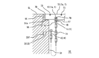
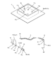
図1〜図11は本考案の盗難防止装置の一形態で、図1は実施形態1の盗難防止装置に係る各構成部品の分解斜視図、図2は図1の盗難防止装置をグレーチングたる溝蓋に取り付ける途中段階の部分斜視図、図3は図2の取付ボルトからボルト頭部がもぎ取られて盗難防止装置の取付け完了状態の部分斜視図、図4は集水桝の溝蓋に適用する盗難防止装置の分解斜視図、図5は図4の溝蓋に盗難防止装置の取付け完了した姿態の部分縦断面図、図6はピット等に適用される鋼板蓋たる溝蓋の表側から見た斜視図、図7が裏側から見た図6の溝蓋と本盗難防止装置との斜視図、図8は実施形態2の盗難防止装置に係る取付金具の斜視図、図9は図8と別態様の取付金具の斜視図、図10は図1の盗難防止装置に図8の取付金具を付加した盗難防止装置を、溝蓋に取り付ける途中段階の部分斜視図で、図2に対応する別形態図である。図11は図10の取付ボルトからボルト頭部がもぎ取られ、盗難防止装置の取付け完了状態の部分斜視図である。
The groove lid anti-theft device (hereinafter simply referred to as “the anti-theft device”) according to the present invention will be described in detail below.
1 to 11 show one embodiment of the anti-theft device of the present invention, FIG. 1 is an exploded perspective view of each component related to the anti-theft device of Embodiment 1, and FIG. 2 is a groove for grating the anti-theft device of FIG. 3 is a partial perspective view of the intermediate stage of attachment to the lid, FIG. 3 is a partial perspective view of the bolt head removed from the attachment bolt of FIG. 2 and the anti-theft device has been installed, and FIG. 4 is applied to the groove lid of the water collecting bowl. 5 is an exploded perspective view of the anti-theft device, FIG. 5 is a partial longitudinal sectional view of a state in which the anti-theft device has been attached to the groove cover of FIG. 4, and FIG. FIG. 7 is a perspective view of the groove lid of FIG. 6 and the antitheft device viewed from the back side, FIG. 8 is a perspective view of a mounting bracket according to the antitheft device of Embodiment 2, and FIG. 9 is different from FIG. FIG. 10 is a perspective view of the mounting bracket of the embodiment, FIG. 10 is a theft prevention device in which the mounting bracket of FIG. 8 is added to the antitheft device of FIG. The device, in partial perspective view in the middle step of attaching to the groove closure, is another form view corresponding to FIG. FIG. 11 is a partial perspective view showing a state in which the bolt head is torn off from the mounting bolt of FIG.

(1)実施形態1
本盗難防止装置は、シャックル1とアンカー3と鎖4とを具備する。
シャックル1は金属製シャックル本体1aと取付ボルト1bとからなる(図1)。シャックル本体1aは図示のごとくU字形に形成された錠杆10の両端部11,12が膨らみのある円盤部に成形される。U字形錠杆の円盤部の一端部11に透孔11aが設けられる一方、他端部12の円盤部に透孔11aと相対向するようにして雌ねじ部12aが設けられる。
(1) Embodiment 1
The antitheft device includes a shackle 1, an anchor 3, and a chain 4.
The shackle 1 comprises a metal shackle body 1a and mounting bolts 1b (FIG. 1). As shown in the figure, the shackle body 1a is formed into a disk portion in which both end portions 11 and 12 of a U-shaped lock rod 10 are swollen. A through hole 11a is provided in one end portion 11 of the disk portion of the U-shaped lock bowl, while a female screw portion 12a is provided in the disk portion of the other end portion 12 so as to face the through hole 11a.

取付ボルト1bは、前記雌ねじ部12aに螺合する雄ねじ部15aを設けたボルト軸15がボルト頭部16から括れ部17を介して延設される金属製ボルトである。取付ボルト1bに係るボルト軸15を透孔11a側から挿通して、雄ねじ部15aを雌ねじ部12aに螺合させて、錠杆10のU字形した開口側を閉じることによって連結金具になる。取付ボルト1bの頭部16は工具や手を使って該取付ボルト1bを回しやすい係合部16bが設けられる。ここでは手やスパナ,ペンチ等で挟んで取付ボルト1bを回し易くする舌片状の係合部16bを形成する。係合部16bはスパナに嵌合する角柱形等にしてもよい。
ボルト頭部16からボルト軸15が延設するが、ボルト頭部16の付け根には括れ部17が形成される。本実施形態は、ボルト頭部16の付け根が細く狭まって括れ部17を形成して鍔部18とつながり、該鍔部からボルト軸15が延びる。ボルト頭部16,括れ部17,鍔部18,ボルト軸15の軸心は図1のごとく一致し、ボルト軸15(ここでは、その先端部)に雄ねじ部15aが形成される。取付ボルト1bを図1の鎖線のごとく透孔11a,雌ねじ部12aに挿通すると、図2のように雄ねじ部15aを該雌ねじ部12aに螺合できる。ボルト軸15の軸長は透孔11a,雌ねじ部12a間の距離と同等又は若干長めに設定される。符号16cは係合部16bに設けた抜孔を示す。
The mounting bolt 1b is a metal bolt in which a bolt shaft 15 provided with a male screw portion 15a that is screwed into the female screw portion 12a is extended from a bolt head 16 via a constricted portion 17. The bolt shaft 15 related to the mounting bolt 1b is inserted from the through hole 11a side, the male screw portion 15a is screwed into the female screw portion 12a, and the U-shaped opening side of the lock rod 10 is closed to form a connecting bracket. The head 16 of the mounting bolt 1b is provided with an engaging portion 16b that is easy to turn the mounting bolt 1b using a tool or hand. Here, a tongue-like engagement portion 16b is formed which is easily pinched by a hand, a spanner, a pliers or the like to turn the mounting bolt 1b. The engaging portion 16b may have a prismatic shape that fits into a spanner.
A bolt shaft 15 extends from the bolt head 16, and a constricted portion 17 is formed at the base of the bolt head 16. In the present embodiment, the base of the bolt head 16 is narrowed to form a constricted portion 17 to be connected to the flange 18, and the bolt shaft 15 extends from the flange. The axial centers of the bolt head portion 16, the constricted portion 17, the flange portion 18, and the bolt shaft 15 coincide as shown in FIG. 1, and a male screw portion 15a is formed on the bolt shaft 15 (here, the tip portion thereof). When the mounting bolt 1b is inserted through the through hole 11a and the female screw portion 12a as shown by the chain line in FIG. 1, the male screw portion 15a can be screwed into the female screw portion 12a as shown in FIG. The axial length of the bolt shaft 15 is set to be equal to or slightly longer than the distance between the through hole 11a and the female screw portion 12a. Reference numeral 16c denotes a hole provided in the engaging portion 16b.

アンカー3は鎖4を側溝9に固定するための金属製部材である。アンカー3は基端側で鎖4と連結し、アンカー3の先端部側はコンクリート製側溝9等に埋め込んで、該アンカー3を介して鎖4が側溝9に固定される。アンカー3の先端側にL字形鉤状部分30fを形成して、側溝9に定着し易くする。本アンカー3はその軸状本体30の基端側に環状体31を形成して鎖4と連結し、さらに該環状体31を形成した基端を該環状体の起点部に溶接固定する。符号31aはその溶接部分を示す。この部位で鎖4が切り離されないようにし、盗難防止対策を万全にする。   The anchor 3 is a metal member for fixing the chain 4 to the side groove 9. The anchor 3 is connected to the chain 4 on the proximal end side, the distal end side of the anchor 3 is embedded in a concrete side groove 9 and the like, and the chain 4 is fixed to the side groove 9 via the anchor 3. An L-shaped hook-shaped portion 30 f is formed on the tip end side of the anchor 3 to facilitate fixing to the side groove 9. The anchor 3 is formed with an annular body 31 on the proximal end side of the shaft-shaped main body 30 and connected to the chain 4, and the proximal end on which the annular body 31 is formed is fixed by welding to the starting point of the annular body. Reference numeral 31a indicates the welded portion. The chain 4 is not cut off at this site, and anti-theft measures are taken.

鎖4は金属製リングをつなぎ合わせてつくった綱である。ここでの鎖4は、一端側が前記シャックル1に連結され、他端側がアンカー3に連結される。鎖4の基端リング41がアンカー3の環状体31の環状形成時に通され、基端リング41と環状体31が連結する。先端リング42がシャックル本体1aに取付ボルト1bを組付ける時に該取付ボルト1bに通され、先端リング42とシャックル1が連結する。さらに、その鎖4は、アンカー3の軸状本体30を側溝9に固定した盗難防止装置の取り付け状態で、シャックル1を介してつながる溝蓋7で側溝9に蓋ができると共に、蓋がされたその溝蓋7を取り外して側溝9わきに置くことのできる長さを有する。   Chain 4 is a rope made by joining metal rings. Here, the chain 4 has one end connected to the shackle 1 and the other end connected to the anchor 3. The proximal ring 41 of the chain 4 is passed through when the annular body 31 of the anchor 3 is formed, and the proximal ring 41 and the annular body 31 are connected. The tip ring 42 is passed through the mounting bolt 1b when the mounting bolt 1b is assembled to the shackle body 1a, and the tip ring 42 and the shackle 1 are connected. In addition, the chain 4 is covered with the groove 9 that is connected to the shackle 1 with the anti-theft device in which the shaft-like main body 30 of the anchor 3 is fixed to the groove 9 and is covered. It has a length that allows the groove lid 7 to be removed and placed on the side groove 9 side.

本盗難防止装置に適用される溝蓋7には、図2のような金属製グレーチング7aがある。グレーチング7aは全体形状が規格化された長方形盤状をなし、主部材72と連結材73と側板70と端板71とを備えるグレーチングとする。多数の金属製帯板からなる主部材72とこれに直交する連結材73とで格子状に形成して、その両側面を側板70で囲む。主部材72の両端を端板71として直方形盤とする。連結材73は通称クロスバーとも呼ばれ、金属製棒状材を捩ったツイスト棒からなる。連結材73は、主部材72をその帯幅方向を垂直起立させ且つ所定ピッチで複数配設した状態を確保した後、これらと直交するようにして所定間隔離して主部材72上面に載置される。その後、主部材72と連結材73とを電気圧接固定して格子状した長方形盤に組み立てられる。符号SLはスリットを示す。尚、主部材72にIバーを通常用いるが、各図はフラットバーで簡単図示する。グレーチング7aは側溝9の上面開口に蓋をするように配設される。符号90は側溝9の底部、符号91は側溝9の側部、符号92は流水溝を示す。
本発明では、斯かるグレーチング7aの一のスリットSLを形成する対向主部材72,72に、軸状の金属製掛止用バー79が固着される。掛止用バー79の両端が溝蓋7を構成する対向主部材72,72の下縁寄りに固着され、該掛止用バーが図2のごとくスリットSLを横断するよう設けられる。
The groove lid 7 applied to the antitheft device includes a metal grating 7a as shown in FIG. The grating 7 a is a rectangular plate having a standardized overall shape, and includes a main member 72, a connecting material 73, a side plate 70, and an end plate 71. A main member 72 made of a large number of metal strips and a connecting member 73 orthogonal to the main member 72 are formed in a lattice shape, and both side surfaces thereof are surrounded by side plates 70. The both ends of the main member 72 are used as end plates 71 to form a rectangular plate. The connecting member 73 is also called a cross bar, and is composed of a twisted bar in which a metal bar is twisted. The connecting members 73 are placed on the upper surface of the main member 72 while maintaining a state in which a plurality of main members 72 are vertically erected in the band width direction and arranged at a predetermined pitch, and are spaced apart from each other by a predetermined interval. The Thereafter, the main member 72 and the connecting member 73 are assembled into a rectangular board having a grid shape by electric pressure contact fixing. Symbol SL indicates a slit. In addition, although I bar | burr is normally used for the main member 72, each figure is simply illustrated with a flat bar | burr. The grating 7 a is disposed so as to cover the upper surface opening of the side groove 9. Reference numeral 90 denotes a bottom portion of the side groove 9, reference numeral 91 denotes a side portion of the side groove 9, and reference numeral 92 denotes a running water groove.
In the present invention, a shaft-like metal latching bar 79 is fixed to the opposing main members 72, 72 forming one slit SL of the grating 7a. Both ends of the latching bar 79 are fixed to the lower edges of the opposed main members 72, 72 constituting the groove lid 7, and the latching bar is provided so as to cross the slit SL as shown in FIG.

そして、本盗難防止装置は、上記構成部品を用いて、両端が溝蓋7に固着された掛止用バー79を跨ぐようにして上方側から嵌入したシャックル本体1aの透孔11aに、取付ボルト1bのボルト軸15を挿通し、さらにボルト軸15の雄ねじ部15aを雌ねじ部12aへ螺着して、図2のごとく掛止用バー79とシャックル1とを連結する。該シャックル1は鎖4の一端側先端リング42と連結し、該鎖4の他端側基端リング41が側溝9に固定したアンカー3に連結されており、溝蓋7がシャックル1を介して鎖4で側溝9に固定される。
本盗難防止装置は、さらに図2の状態からボルト頭部16を締め付けることにより、図3のごとく括れ部17でボルト頭部16が取付ボルト1bからもぎ取られる構成になっている。ボルト頭部16が取付ボルト1bからもぎ取られることによって、もはやシャックル本体1aから取付ボルト1bを取り外せなくなる。ボルト頭部16がないため、スパナ等の工具が使えず、盗難防止に完全を期すことができる。
The anti-theft device uses the above-described components to attach the mounting bolts to the through holes 11a of the shackle body 1a fitted from the upper side so as to straddle the latching bars 79 fixed to the groove lid 7 at both ends. The bolt shaft 15 of 1b is inserted, and the male screw portion 15a of the bolt shaft 15 is screwed to the female screw portion 12a to connect the latching bar 79 and the shackle 1 as shown in FIG. The shackle 1 is connected to one end side ring 42 of the chain 4, the other end side base ring 41 of the chain 4 is connected to the anchor 3 fixed to the side groove 9, and the groove lid 7 is connected via the shackle 1. The chain 4 is fixed to the side groove 9.
The anti-theft device is configured such that when the bolt head 16 is further tightened from the state shown in FIG. 2, the bolt head 16 is removed from the mounting bolt 1b by the constricted portion 17 as shown in FIG. By removing the bolt head 16 from the mounting bolt 1b, the mounting bolt 1b can no longer be removed from the shackle body 1a. Since there is no bolt head 16, a tool such as a spanner cannot be used, and complete prevention can be achieved.

次に、上記各構成部品を用いて、盗難防止装置を側溝9に取り付ける一例を説明する。
アンカー3の環状体31に鎖4の基端リング41を連結して、環状体31の基端を該環状体31の起点部に溶接固定する。また、アンカー3の鉤状部分30fのある軸状本体30部を、現場設置される側溝9の段差部91a近くの側部91に埋設固定する(図2)。
続いて、側溝9の上面開口に蓋をする溝蓋7に固着された掛止用バー79を跨ぐようにしてシャックル本体1aを嵌入する。その後、取付ボルト1bのボルト軸15を透孔11aに挿通し、次いで、鎖4の先端リング42に通し、さらに該ボルト軸15の雄ねじ部15aを雌ねじ部12aへ螺着して、掛止用バー79と鎖4とをシャックル1で連結する。さらに、図2の円内矢印回転方向にボルト頭部16を締め付けることにより括れ部17で該ボルト頭部16を取付ボルト1bからもぎ取る(図3)。かくして、取付ボルト1bに先端リング42が通されたことによって、掛止用バー79,シャックル1,鎖4,アンカー3が連結する。掛止用バー79は溝蓋7に固着されており、またアンカー3は側溝9に埋設固定されているため、溝蓋7が鎖4で側溝9につながれる。本盗難防止装置による側溝9への溝蓋7の取付けが完成する。
Next, an example in which the antitheft device is attached to the side groove 9 using each of the above components will be described.
The base end ring 41 of the chain 4 is connected to the ring body 31 of the anchor 3, and the base end of the ring body 31 is welded and fixed to the starting point of the ring body 31. Further, the shaft-shaped main body 30 portion having the flange-shaped portion 30f of the anchor 3 is embedded and fixed to the side portion 91 near the step portion 91a of the side groove 9 installed in the field (FIG. 2).
Subsequently, the shackle body 1a is fitted so as to straddle the latching bar 79 fixed to the groove lid 7 that covers the upper surface opening of the side groove 9. Thereafter, the bolt shaft 15 of the mounting bolt 1b is inserted into the through-hole 11a, and then passed through the end ring 42 of the chain 4, and the male screw portion 15a of the bolt shaft 15 is screwed to the female screw portion 12a for latching. The bar 79 and the chain 4 are connected by the shackle 1. Further, the bolt head 16 is removed from the mounting bolt 1b by the constricted portion 17 by tightening the bolt head 16 in the direction of the arrow in the circle in FIG. 2 (FIG. 3). Thus, the hooking bar 79, the shackle 1, the chain 4, and the anchor 3 are connected by passing the tip ring 42 through the mounting bolt 1b. Since the latching bar 79 is fixed to the groove lid 7 and the anchor 3 is embedded and fixed in the side groove 9, the groove lid 7 is connected to the side groove 9 by the chain 4. The attachment of the groove lid 7 to the side groove 9 by the antitheft device is completed.

溝蓋7に関しては、前記グレーチング7aに限らず種々のものを用いることができる。例えば図4〜図7のような溝蓋7である。図4は集水桝蓋7bたる他態様の溝蓋7に適用する本盗難防止装置の斜視図である。この集水桝蓋7bは、図1の長方形盤のグレーチング7aと基本構成がほぼ同じで、主部材72とこれに直交する連結材73とで格子状に形成して、その両側面を側板70で囲む。主部材72の両端を端板71として正方形盤とする。斯かる集水桝蓋7bの一のスリットSLを形成する対向主部材72,72に、軸状の金属製掛止用バー79が固着される。掛止用バー79の両端が溝蓋7を構成する対向主部材72,72に固着され、該掛止用バー79が図4のごとくスリットSLを横断するよう設けられる。
そして、盗難防止装置は、図1〜図3と同様、掛止用バー79を跨ぐようにして嵌入したシャックル本体1aの透孔11aに、取付ボルト1bのボルト軸15を挿通し、次いで、該ボルト軸を鎖の先端リング42に通し、さらにボルト軸15の雄ねじ部15aを雌ねじ部12aへ螺着して、掛止用バー79とシャックル1とを連結する。掛止用バー79は該シャックル1を介して鎖4の一端側と連結し、該鎖4の他端側が側溝9に固定したアンカー3に連結されていることから、蓋7がシャックル1を介して鎖4で側溝9に固定される。そうして、ボルト頭部16の締め付けにより、図5のごとく括れ部17でボルト頭部16が取付ボルト1bからもぎ取られる。
Regarding the groove lid 7, not only the grating 7a but also various ones can be used. For example, a groove lid 7 as shown in FIGS. FIG. 4 is a perspective view of the anti-theft device applied to the groove lid 7 of another embodiment as the water collecting lid 7b. This drainage lid 7b has substantially the same basic structure as the grating 7a of the rectangular plate in FIG. 1, and is formed in a lattice shape with a main member 72 and a connecting member 73 orthogonal thereto, and both side surfaces thereof are side plates 70. Surround with. Both ends of the main member 72 are square plates with end plates 71. A shaft-shaped metal latching bar 79 is fixed to the opposing main members 72 and 72 forming one slit SL of the water collecting lid 7b. Both ends of the latching bar 79 are fixed to the opposing main members 72, 72 constituting the groove lid 7, and the latching bar 79 is provided so as to cross the slit SL as shown in FIG.
The antitheft device inserts the bolt shaft 15 of the mounting bolt 1b into the through hole 11a of the shackle body 1a inserted so as to straddle the latching bar 79, as in FIGS. The bolt shaft is passed through the chain end ring 42, and the male thread portion 15 a of the bolt shaft 15 is screwed to the female thread portion 12 a to connect the latching bar 79 and the shackle 1. The latching bar 79 is connected to one end side of the chain 4 through the shackle 1, and the other end side of the chain 4 is connected to the anchor 3 fixed to the side groove 9, so that the lid 7 is connected to the shackle 1. The chain 4 is fixed to the side groove 9. Then, by tightening the bolt head 16, the bolt head 16 is torn off from the mounting bolt 1b at the constricted portion 17 as shown in FIG.

溝蓋7は図6,図7のような他態様品でもよい。図6,図7はピットなどで用いられる鋼板蓋7cたる溝蓋7の斜視図である。この鋼板蓋7cは蓋本体を縞鋼板等の板状蓋75で形成し、裏面75bにピット内に嵌合する枠部材76を固着する。符号77は鋼板蓋7cを持ち上げるための把手、符号77aは裏面側に設けた把手のストッパを示す。
本盗難防止装置は、掛止用バー79の一端を鋼板蓋7cの枠部材76に固着する一方、掛止用バー79の他端を該枠部材内の板状蓋75の裏面75bに固着し、該掛止用バーを跨いでシャックル本体1aが嵌入できるように設定する。後は、図1〜図3や図4,図5と同様で、掛止用バー79に嵌入したシャックル本体1aの通孔21と鎖4の先端リング42に、取付ボルト1bを挿通し、ボルト軸15を雌ねじ部12aへ螺着して、掛止用バー79と鎖4とをシャックル1で連結する。さらにボルト頭部16の締め付けにより括れ部17でボルト頭部16が取付ボルト1bからもぎ取られる構成である。
The groove lid 7 may be another embodiment as shown in FIGS. 6 and 7 are perspective views of the groove lid 7 which is a steel plate lid 7c used in a pit or the like. The steel plate lid 7c has a lid body formed of a plate-like lid 75 such as a striped steel plate, and a frame member 76 fitted in the pit is fixed to the back surface 75b. Reference numeral 77 denotes a handle for lifting the steel plate lid 7c, and reference numeral 77a denotes a handle stopper provided on the back surface side.
In this antitheft device, one end of the latching bar 79 is fixed to the frame member 76 of the steel plate lid 7c, and the other end of the latching bar 79 is fixed to the back surface 75b of the plate-like lid 75 in the frame member. The shackle body 1a is set so as to be able to be fitted over the hooking bar. After that, as in FIGS. 1 to 3, 4, and 5, the mounting bolt 1 b is inserted into the through hole 21 of the shackle body 1 a and the end ring 42 of the chain 4 fitted into the latching bar 79. The shaft 15 is screwed onto the female threaded portion 12a, and the latching bar 79 and the chain 4 are connected by the shackle 1. Further, the bolt head 16 is removed from the mounting bolt 1b at the constricted portion 17 by tightening the bolt head 16.

このように構成した盗難防止装置は、掛止用バー79を跨ぐようにしてシャックル本体1aを嵌入し、取付ボルト1bのボルト軸15を透孔11aと鎖4の先端リング42に挿通し、そのボルト軸15の雄ねじ部15aを雌ねじ部12aへ螺着して、掛止用バー79とシャックル1、鎖4を連結した後、ボルト頭部16を締め付けて括れ部17でボルト頭部16が取付ボルト1bからもぎ取られるので、一旦、掛止用バー79とシャックル1、鎖4が連結されれば、もはや取り外すことが困難になる。ボルト頭部16は括れ部17が形成されているので容易にもぎ取ることができ作業性に優れる。ボルト頭部16がもぎ取られることによって、工具等を用いるにしても、ボルト軸15を回すのに把持する所がない。従って、この盗難防止装置は鎖4の他端側基端リング41をアンカー3に取付け、該アンカー3を側溝9に固定すれば、溝蓋7が盗難被害に遭う虞がない。管理者といえども溝蓋7を取り外すことができない。汎用ボルト等で締結され、市販スパナ等によって溝蓋7が簡単に取り外される従来品と全く異なり、盗難防止対策が万全となる。
勿論、管理者もシャックル本体1aから取付ボルト1bを抜いて溝蓋7を取り外すことが困難になるが、何ら支障はない。側溝9内の掃除等で側溝9に蓋をしていた溝蓋7が定期的に取り外されたりするが、その溝蓋7は側溝9の脇に通常置かれる。側溝9の脇に置けるよう鎖4の長さを確保すれば足りる。
また、本盗難防止装置は、既述のごとくシャックル1とアンカー3と鎖4とからなるごく簡便な構成で低コスト対応できる。溝蓋7への本盗難防止装置の取り付けも、両端が溝蓋7に固着された掛止用バー79を跨ぐようにしてシャックル本体1aを嵌入後、これに取付ボルトを螺着し、さらに螺着強化してボルト頭部16をもぎ取り、シャックル1,鎖4を介して基端リング41に連結したアンカー3を側溝9へ固定するだけであり、その取り付けに労力,時間をさほど要しない。しかも、グレーチング7aや集水桝蓋7bなどの様々な溝蓋7に対して完璧な盗難防止を実現することができ極めて有益となる。
さらに、アンカー3が軸状本体30の基端側に環状体31を形成して鎖4と連結され、且つ該環状体31を形成した基端が該環状体31の起点部と溶接固定されれば、このアンカー3の環状体31から切り離されて溝蓋7が持ち去られるといった問題も解消し、盗難防止対策は盤石になる。
The anti-theft device configured in this manner inserts the shackle body 1a so as to straddle the latching bar 79, passes the bolt shaft 15 of the mounting bolt 1b through the through hole 11a and the tip ring 42 of the chain 4, and After the male screw portion 15a of the bolt shaft 15 is screwed to the female screw portion 12a and the latching bar 79, the shackle 1, and the chain 4 are connected, the bolt head portion 16 is tightened and the bolt head portion 16 is attached by the constricted portion 17. Since it is torn off from the bolt 1b, once the hooking bar 79, the shackle 1, and the chain 4 are connected, it is difficult to remove. Since the bolt head 16 is formed with the constricted portion 17, the bolt head 16 can be easily scraped off and has excellent workability. Since the bolt head 16 is torn off, there is no place to grip the bolt shaft 15 even if a tool or the like is used. Therefore, in this antitheft device, if the base end ring 41 on the other end side of the chain 4 is attached to the anchor 3 and the anchor 3 is fixed to the side groove 9, there is no possibility that the groove cover 7 will be damaged. Even the administrator cannot remove the groove lid 7. Unlike the conventional product, which is fastened with a general-purpose bolt or the like and the groove lid 7 is easily removed by a commercially available spanner or the like, the anti-theft measures are perfect.
Of course, it is difficult for the administrator to remove the groove lid 7 by removing the mounting bolt 1b from the shackle body 1a, but there is no problem. The groove lid 7 that covers the side groove 9 is periodically removed by cleaning or the like in the side groove 9, but the groove lid 7 is usually placed beside the side groove 9. It is sufficient to secure the length of the chain 4 so that it can be placed beside the side groove 9.
Further, as described above, the anti-theft device can cope with a low cost with a very simple configuration including the shackle 1, the anchor 3, and the chain 4. The anti-theft device is also attached to the groove lid 7 by inserting the shackle body 1a so that both ends of the anti-theft bar 79 are fixed to the groove lid 7 and then screwing the mounting bolts on the shackle body 1a. The bolt head 16 is peeled off and tightened, and the anchor 3 connected to the proximal ring 41 via the shackle 1 and the chain 4 is simply fixed to the side groove 9, so that much effort and time are not required for the attachment. Moreover, perfect theft prevention can be realized for various groove lids 7 such as the grating 7a and the water collecting lid 7b, which is extremely useful.
Further, the anchor 3 forms an annular body 31 on the proximal end side of the shaft-shaped main body 30 and is connected to the chain 4, and the proximal end forming the annular body 31 is welded and fixed to the starting portion of the annular body 31. For example, the problem that the groove lid 7 is removed by being separated from the annular body 31 of the anchor 3 is solved, and the anti-theft measure is a stone.

(2)実施形態2
本盗難防止装置は、図8〜図11のごとくで、構成部品として図1〜図7の盗難防止装置にさらに取付金具2を付加するものである。図8は図1〜図7の盗難防止装置に付加される補助部品たる取付金具2を示す。
前記グレーチング7aや集水桝蓋7bでは、掛止用バー79の両端が溝蓋7を構成する対向主部材72,72に固着され、該掛止用バー79がスリットSLを横断するよう設けられる。ここで、一の主部材72に掛止用バー79を担わせようとすると、主部材72の帯幅が大きすぎてこれを跨ぐようにしてシャックル本体1aを嵌入することが困難になる。主部材72とシャックル1を連結することができない。この一の主部材72を掛止用バー79に用いるときに、該取付金具2を介して主部材72とシャックル1とが連結される。
(2) Embodiment 2
As shown in FIGS. 8 to 11, the anti-theft device adds a mounting bracket 2 to the anti-theft device of FIGS. 1 to 7 as a component. FIG. 8 shows a mounting bracket 2 as an auxiliary part added to the antitheft device of FIGS.
In the grating 7a and the water collecting lid 7b, both ends of the latching bar 79 are fixed to the opposing main members 72, 72 constituting the groove lid 7, and the latching bar 79 is provided so as to cross the slit SL. . Here, if one main member 72 is to carry the latching bar 79, the band width of the main member 72 is too large, and it is difficult to fit the shackle body 1a so as to straddle it. The main member 72 and the shackle 1 cannot be connected. When this one main member 72 is used for the latching bar 79, the main member 72 and the shackle 1 are connected via the mounting bracket 2.

前記取付金具2は帯板片の成形加工品で、一対の脚部2aを対向させて両方の上端を天板部2bで連結して側面視略コ字形とする。両脚部2aの下端寄りにはそれぞれ通孔21が対向するように設けられる。符号εは取付金具2のコ字形開口隙間で、この隙間幅が主部材72の厚みよりも大きく設定される。符号22は側面視コ字形内側に膨らむ突起、符号22aは突起を形成するための窪みを示す。
該取付金具2は、グレーチング7aの一の主部材72を掛止用バー79として、これを跨いで図10のごとく上方側から嵌入すると、脚部2aに設けた通孔21の部分が該主部材よりも下方へ突出する。本盗難防止装置は、前もって先端リング42を通したシャックル本体1aに係る透孔11aと雌ねじ部12aとを、該通孔21,21の部位へ外側から重ね合わせる。さらに、取付ボルト1bのボルト軸15を透孔11aと両通孔21とに挿通し、且つボルト軸15の雄ねじ部15aを雌ねじ部12aへ螺着して、取付金具2を介して主部材72たる掛止用バー79とシャックル1とを連結する。しかる後、ボルト頭部16を締め付けることにより括れ部17で該ボルト頭部16が取付ボルト1bからもぎ取られる(図11)。他の構成は、図1〜図3の盗難防止装置と同様で、その説明を省く。図1〜図3と同一符号は同一又は相当部分を示す。
The mounting bracket 2 is a strip piece processed product, and a pair of leg portions 2a are opposed to each other, and both upper ends thereof are connected by a top plate portion 2b so as to be substantially U-shaped in a side view. Near the lower ends of both legs 2a, through holes 21 are provided so as to face each other. Symbol ε is a U-shaped opening gap of the mounting bracket 2, and the gap width is set larger than the thickness of the main member 72. Reference numeral 22 indicates a protrusion that swells inwardly in a U shape, and reference numeral 22a indicates a recess for forming the protrusion.
When the fitting 2 is fitted from the upper side as shown in FIG. 10 with the main member 72 of the grating 7a as the latching bar 79 and straddling it, the portion of the through hole 21 provided in the leg 2a is the main bar 72. Projects downward from the member. In this antitheft device, the through hole 11a and the female threaded portion 12a of the shackle body 1a through which the tip ring 42 has been passed are overlapped with the through holes 21 and 21 from the outside. Furthermore, the bolt shaft 15 of the mounting bolt 1b is inserted into the through hole 11a and the two through holes 21, and the male screw portion 15a of the bolt shaft 15 is screwed to the female screw portion 12a. The slack bar 79 and the shackle 1 are connected. Thereafter, by tightening the bolt head 16, the bolt head 16 is removed from the mounting bolt 1 b at the constricted portion 17 (FIG. 11). Other configurations are the same as those of the antitheft device of FIGS. 1 to 3 indicate the same or corresponding parts.

前記取付金具2に関しては図8に代えて例えば図9のものとすることができる。図8の取付金具2は図7のものより帯板片の幅を大きくして、各脚部2aの下端角域から斜め上方に向け複数(ここでは3個)の通孔21を設ける。符号24は切欠部を示す。グレーチング7aや集水桝蓋7bには様々なサイズがあり、そのサイズに応じて主部材72の大きさも違っている。図9の取付金具2は、小サイズから大サイズまである主部材72に対し、取付ボルト1bが挿通する通孔21を選んで対応できる。一つの取付金具2で適用可能な溝蓋7の仕様範囲が広がる。   The mounting bracket 2 can be, for example, that of FIG. 9 instead of FIG. The mounting bracket 2 of FIG. 8 has a width of the strip plate larger than that of FIG. 7, and is provided with a plurality (three in this case) of through holes 21 obliquely upward from the lower end corner area of each leg portion 2a. Reference numeral 24 denotes a notch. There are various sizes of the grating 7a and the water collecting lid 7b, and the size of the main member 72 differs depending on the size. The mounting bracket 2 of FIG. 9 can cope with the main member 72 having a small size to a large size by selecting the through hole 21 through which the mounting bolt 1b is inserted. The specification range of the groove lid 7 that can be applied with one mounting bracket 2 is expanded.

このように構成した盗難防止装置は、実施形態1の効果に加え、グレーチング7aや集水桝蓋7bの一の主部材72を掛止用バー79としてそのまま用いることができる。盗難防止装置用に掛止用バー79を設けなくて済むので、既存の溝蓋7等にも本装置を簡単に取り付けることができ、その適用範囲が広がりさらに有益となる。   In addition to the effects of the first embodiment, the antitheft device configured as described above can use the main member 72 of the grating 7a and the water collecting lid 7b as the latching bar 79 as it is. Since it is not necessary to provide the latching bar 79 for the anti-theft device, the present device can be easily attached to the existing groove lid 7 and the like, and its application range is widened and further useful.

尚、本考案においては前記実施形態に示すものに限られず、目的,用途に応じて本考案の範囲で種々変更できる。シャックル1,取付金具2,アンカー3,鎖4,溝蓋7,側溝9等の形状,大きさ,個数,材質等は用途に合わせて適宜選択できる。   The present invention is not limited to the one shown in the above embodiment, and various modifications can be made within the scope of the present invention depending on the purpose and application. The shape, size, number, material, and the like of the shackle 1, the mounting bracket 2, the anchor 3, the chain 4, the groove lid 7, and the side groove 9 can be appropriately selected according to the application.

実施形態1の盗難防止装置に係る各構成部品の分解斜視図である。It is a disassembled perspective view of each component concerning the antitheft device of Embodiment 1. 図1の盗難防止装置をグレーチングたる溝蓋に取り付ける途中段階の部分斜視図である。It is a fragmentary perspective view in the middle of attaching the antitheft device of FIG. 1 to the groove lid which is grating. 図2の取付ボルトからボルト頭部がもぎ取られて盗難防止装置の取付け完了状態の部分斜視図である。FIG. 3 is a partial perspective view showing a state in which the bolt head is torn off from the mounting bolt of FIG. 集水桝の溝蓋に適用する盗難防止装置の分解斜視図である。It is a disassembled perspective view of the anti-theft device applied to the ditch cover of a catchment. 図4の溝蓋に盗難防止装置の取付け完了した姿態の部分縦断面図である。FIG. 5 is a partial longitudinal sectional view of a state in which the antitheft device has been attached to the groove lid of FIG. 4. ピット等に適用される鋼板蓋たる溝蓋の表側から見た斜視図である。It is the perspective view seen from the front side of the groove lid which is a steel plate lid applied to pits. 裏側から見た図6の溝蓋と本盗難防止装置との斜視図である。FIG. 7 is a perspective view of the groove lid and the antitheft device of FIG. 6 as viewed from the back side. 実施形態2の盗難防止装置に係る取付金具の斜視図である。It is a perspective view of the attachment metal fitting concerning the antitheft device of Embodiment 2. 図8と別態様の取付金具の斜視図である。It is a perspective view of the attachment metal fitting of another aspect from FIG. 図1の盗難防止装置に図8の取付金具を付加した盗難防止装置を、溝蓋に取り付ける途中段階の部分斜視図で、図2に対応する別態様図である。FIG. 9 is a partial perspective view of the anti-theft device in which the mounting bracket of FIG. 8 is added to the anti-theft device of FIG. 図10の取付ボルトからボルト頭部がもぎ取られて盗難防止装置の取付け完了状態の部分斜視図である。FIG. 11 is a partial perspective view showing a state in which the bolt head is torn from the mounting bolt of FIG.

符号の説明Explanation of symbols

1 シャックル
1a シャックル本体
1b 取付ボルト
10 錠杆
11a 透孔
12a 雌ねじ部
15a 雄ねじ部
2 取付金具
2a 脚部
2b 天板部
21 通孔
3 アンカー
30 軸状本体
31 環状体
4 鎖
7 溝蓋
72 主部材
79 掛止用バー
DESCRIPTION OF SYMBOLS 1 Shackle 1a Shackle body 1b Mounting bolt 10 Locking rod 11a Through-hole 12a Female thread part 15a Male thread part 2 Mounting bracket 2a Leg part 2b Top plate part 21 Through-hole 3 Anchor 30 Shaft-shaped main body 31 Ring body 4 Chain 7 Groove cover 72 Main member 79 Bar for hanging

Claims (3)

U字形に形成された錠杆(10)の一端部に透孔(11a)を設ける一方、他端部に雌ねじ部(12a)を設けたシャックル本体(1a)と、該雌ねじ部に螺合する雄ねじ部(15a)を設けたボルト軸(15)がボルト頭部(16)から括れ部(17)を介して延設される取付けボルト(1b)とを備える金属製シャックル(1)と、
一端側を該シャックルに連結し他端側がアンカー(3)に連結される鎖(4)と、を具備し、
両端が溝蓋(7)に固着された掛止用バー(79)を跨ぐようにして嵌入した前記シャックル本体(1a)の透孔(11a)に、前記取付けボルト(15)のボルト軸(15)を挿通し、且つ該ボルト軸の雄ねじ部(15a)を前記雌ねじ部(12a)へ螺着して、係止用バー(79)とシャックル(1)とを連結し、さらにボルト頭部(16)を締め付けることにより前記括れ部(17)で該ボルト頭部(16)が前記取付ボルト(1b)からもぎ取られるようにしたことを特徴とする溝蓋の盗難防止装置。
A shackle body (1a) provided with a through hole (11a) at one end of a U-shaped lock rod (10) and a female thread (12a) at the other end is screwed into the female thread. A metal shackle (1) provided with a mounting bolt (1b) in which a bolt shaft (15) provided with a male screw portion (15a) extends from a bolt head (16) via a constricted portion (17),
A chain (4) having one end connected to the shackle and the other end connected to an anchor (3),
Bolt shafts (15) of the mounting bolts (15) are inserted into the through holes (11a) of the shackle body (1a) fitted so as to straddle the latching bars (79) fixed at both ends to the groove lid (7). ) And the male screw portion (15a) of the bolt shaft is screwed to the female screw portion (12a) to connect the locking bar (79) and the shackle (1), and the bolt head ( An antitheft device for a groove lid, wherein the bolt head (16) is torn off from the mounting bolt (1b) at the constricted portion (17) by tightening 16).
一対の脚部(2a)を対向させて両方の上端を天板部(2b)で連結して側面視略コ字形とし、且つ両脚部(2a)の下端寄りにそれぞれ通孔(21)を設けた取付金具(2)をさらに具備し、
溝蓋(7)に係る一の主部材(72)の掛止用バー(79)を跨ぐようにして嵌入した前記取付金具(2)に係る両通孔(21)の部位へ、前記シャックル本体(1a)の透孔(11a)と雌ねじ部(12a)とを外側から重ね合わせ、前記取付けボルト(1b)のボルト軸(15)を該透孔(11a)と該両通孔(21)とに挿通し、且つ該ボルト軸(15a)の雄ねじ部(15a)を前記雌ねじ部(12a)へ螺着して、該取付金具を介して係止用バー(79)とシャックル(1)とを連結する請求項1記載の溝蓋の盗難防止装置。
A pair of legs (2a) are opposed to each other and the upper ends of both are connected by a top plate (2b) to form a substantially U-shape in side view, and through holes (21) are provided near the lower ends of both legs (2a). Further comprising a mounting bracket (2),
The shackle body to the part of the two through holes (21) of the mounting bracket (2) fitted so as to straddle the latching bar (79) of one main member (72) of the groove lid (7) The through hole (11a) of the (1a) and the female screw portion (12a) are overlapped from the outside, and the bolt shaft (15) of the mounting bolt (1b) is connected to the through hole (11a) and the both through holes (21). And the male screw part (15a) of the bolt shaft (15a) is screwed to the female screw part (12a), and the locking bar (79) and the shackle (1) are connected via the mounting bracket. The antitheft device for a groove lid according to claim 1 to be connected.
前記アンカー(3)が軸状本体(30)の基端側に環状体(31)を形成して前記鎖(4)と連結され、さらに該環状体を形成した基端が該環状体の起点部と溶接固定される請求項1又は2記載の溝蓋の盗難防止装置。 The anchor (3) is connected to the chain (4) by forming an annular body (31) on the proximal end side of the shaft-shaped main body (30), and the proximal end forming the annular body is the starting point of the annular body The antitheft device for a groove lid according to claim 1 or 2, which is welded to the portion.
JP2008002423U 2008-04-16 2008-04-16 Groove cover anti-theft device Expired - Lifetime JP3142803U (en)

Priority Applications (1)

Application Number Priority Date Filing Date Title
JP2008002423U JP3142803U (en) 2008-04-16 2008-04-16 Groove cover anti-theft device

Applications Claiming Priority (1)

Application Number Priority Date Filing Date Title
JP2008002423U JP3142803U (en) 2008-04-16 2008-04-16 Groove cover anti-theft device

Publications (1)

Publication Number Publication Date
JP3142803U true JP3142803U (en) 2008-06-26

Family

ID=43292784

Family Applications (1)

Application Number Title Priority Date Filing Date
JP2008002423U Expired - Lifetime JP3142803U (en) 2008-04-16 2008-04-16 Groove cover anti-theft device

Country Status (1)

Country Link
JP (1) JP3142803U (en)

Cited By (2)

* Cited by examiner, † Cited by third party
Publication number Priority date Publication date Assignee Title
JP2015017405A (en) * 2013-07-10 2015-01-29 株式会社淀川製鋼所 Side ditch unit
CN114809096A (en) * 2022-04-21 2022-07-29 博雅慧聚科技发展有限公司 Intelligent well lid anti-theft sensing device based on Internet of things

Similar Documents

Publication Publication Date Title
EP2526331B1 (en) Tie device for elongate articles
JP3142803U (en) Groove cover anti-theft device
JP2009097311A (en) Mounting structure of grating
JP2008288115A (en) Battery terminal
JP2009299376A (en) Connection structure of grating
JP5137194B2 (en) Grating connection structure
JP3135118U (en) Grating mounting bracket
JP2019218835A (en) Closing-cover fixation structure
WO2002073762A1 (en) Method and means for combating theft of underground cables
JP3127864U (en) Tool for attaching master rope to column reinforcement
JP5453478B2 (en) Grating
JP5723251B2 (en) Anti-theft device for grating
JP4782149B2 (en) Grating
JP3104579U (en) Bolt detent plate
JP3207270U (en) Groove cover
KR200395191Y1 (en) An apparatus for construction fence fabric
KR20190001414U (en) Fixing jig for connecting nut of flange
JP5183523B2 (en) Grating connector
JP2014122533A (en) Fixture for grating
KR101541905B1 (en) Pipe clamp
JP6695591B2 (en) Wrench tool
JP3139428U (en) Concrete block connector.
JP2009191470A (en) Connection structure of grating
JP2018028237A (en) Ditch cover
JP2000045376A (en) Mounting structure of grating and receiving frame member

Legal Events

Date Code Title Description
R150 Certificate of patent or registration of utility model

Free format text: JAPANESE INTERMEDIATE CODE: R150

FPAY Renewal fee payment (event date is renewal date of database)

Free format text: PAYMENT UNTIL: 20110604

Year of fee payment: 3

FPAY Renewal fee payment (event date is renewal date of database)

Free format text: PAYMENT UNTIL: 20110604

Year of fee payment: 3

FPAY Renewal fee payment (event date is renewal date of database)

Free format text: PAYMENT UNTIL: 20140604

Year of fee payment: 6

EXPY Cancellation because of completion of term