JP3141357U - Mask sterilizer - Google Patents
Mask sterilizer Download PDFInfo
- Publication number
- JP3141357U JP3141357U JP2008000838U JP2008000838U JP3141357U JP 3141357 U JP3141357 U JP 3141357U JP 2008000838 U JP2008000838 U JP 2008000838U JP 2008000838 U JP2008000838 U JP 2008000838U JP 3141357 U JP3141357 U JP 3141357U
- Authority
- JP
- Japan
- Prior art keywords
- mask
- heating element
- mask sterilizer
- heat
- case
- Prior art date
- Legal status (The legal status is an assumption and is not a legal conclusion. Google has not performed a legal analysis and makes no representation as to the accuracy of the status listed.)
- Expired - Fee Related
Links
Images


Abstract
【課題】携行することができるマスク用殺菌器を提供すること。
【解決手段】ヒンジで連結された一対の有縁平皿状の外装部材を有し、開放端は係止可能な開閉構造のケース1と、それぞれ前記外装部材に取り付けられ、中央にマスクの収納空間を有する一対の断熱体2と、前記断熱体に設けられ前記収納空間を加熱する発熱体3と、をそなえたマスク殺菌器。
【選択図】図1Disclosed is a mask sterilizer which can be carried.
A case 1 having a pair of framed flat-plate-shaped exterior members connected by hinges and having an open end that can be locked and an opening / closing structure case 1 are attached to each of the exterior members, and a mask storage space in the center. A mask sterilizer provided with a pair of heat insulators 2 having a heating element 3 provided on the heat insulator and heating the storage space.
[Selection] Figure 1
Description
本考案は、人の口鼻部に装着するマスクを殺菌するための殺菌器に係わり、とくに携行して使用できるものに関する。 The present invention relates to a sterilizer for sterilizing a mask to be worn on a person's mouth and nose, and particularly relates to a sterilizer that can be carried and used.
近年、世界的に拡がりを見せる鳥インフルエンザなどの空気中に浮遊する菌、ウィルスによる伝染性の病気を予防するには、吸気に含まれる菌、ウィルスを除去する意味でマスクの着用が有効と認識されている(特許文献1参照)。 In recent years, it has been recognized that wearing a mask is effective in removing germs and viruses contained in inhalation in order to prevent infectious diseases caused by viruses and viruses floating in the air, such as bird flu, which has been spreading worldwide. (See Patent Document 1).
マスクは、一旦着用したらその後は廃棄するか、再利用するのであれば殺菌することが望ましい。また、使用済みのマスクは廃棄するよりは、できれば再利用することが望ましい。
しかしながら、マスクを殺菌するための適当な機器が存在しないのと、例えば外出が長時間にわたる場合は殺菌する機会がないことから、適度に使用してから廃棄するか、あるいは長時間にわたり使用し続けることになる。 However, since there is no suitable device for sterilizing the mask, and there is no opportunity to sterilize, for example, when going out for a long time, it is discarded after being used moderately or used for a long time. It will be.
本考案は上述の点を考慮してなされたもので、携行することができるマスク用殺菌器を提供することを目的とする。 The present invention has been made in consideration of the above points, and an object thereof is to provide a mask sterilizer that can be carried.
上記目的達成のため、本考案では、
ヒンジで連結された一対の有縁平皿状の外装部材を有し、開放端が係止可能な開閉構造のケースと、
それぞれ前記外装部材に取り付けられ、中央にマスクの収納空間を有する一対の断熱体と、
前記断熱体に設けられ前記収納空間を加熱する発熱体と、
をそなえたマスク殺菌器、
を提供するものである。
In order to achieve the above object, in the present invention,
A case of an opening and closing structure having a pair of framed flat dish-shaped exterior members connected by hinges, and capable of locking an open end;
A pair of heat insulators each attached to the exterior member and having a mask storage space in the center;
A heating element provided in the heat insulator to heat the storage space;
With mask sterilizer,
Is to provide.
本考案は上述のように、ケースに発熱体を内蔵し、マスクを収容して加熱殺菌するようにしたため、携行して適時に簡便にマスクを殺菌することができる。 As described above, according to the present invention, since the heating element is built in the case, the mask is accommodated and heat sterilized, the mask can be carried and easily sterilized in a timely manner.
以下、添付図面を参照して本考案の実施の形態を説明する。 Embodiments of the present invention will be described below with reference to the accompanying drawings.
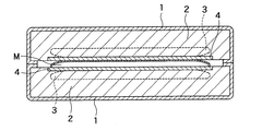
図1は、本考案の実施例1の内部構造を示した断面図である。この実施例1は、一対のほぼ有縁平皿状の外装部材が腹合わせに組み合わされて構成されるケース1内に、断熱材2を介して発熱体3が設置され、発熱体3の断熱体2とは反対側には、たとえば金属製の導熱板4が配されている。
FIG. 1 is a cross-sectional view showing the internal structure of
これにより、ケース1を開くと、導熱板4,4が露出し、一方の導熱板4上にマスクMを載置してケース1を閉じると、図示のように、マスクMが2枚の導熱板4,4間に挟まれた状態となる。そして、発熱体3の発する熱が導熱板4,4を介して効率的にマスクMに与えられ、マスクMが加熱殺菌される。
Thus, when the
鳥インフルエンザ・ウィルスの場合、仮に60℃では10分の加熱によりほぼ完全に不活化することが知られている(温度を変えれば時間も変わる。)。そこで、発熱体3としてマスクを不活化加熱することができるものを選ぶ。他の菌とかウィルスについては、より適当な温度、時間が選ばれることになる。 In the case of the avian influenza virus, it is known that it is almost completely inactivated by heating for 10 minutes at 60 ° C. (the time changes if the temperature is changed). Therefore, a heating element that can inactivate the mask is selected. For other bacteria and viruses, a more appropriate temperature and time will be selected.
そのような発熱体3としては、電気ヒータおよび化学的発熱体がある。電気ヒータであれば、例えばチップ型回路を用い温度、加熱時間を自動制御して自動停止する回路を含めて自由に設計することができる反面、電源が必要である。また、化学的発熱体としては、鉄の酸化発熱を利用するもの、および生石灰の吸水発熱を利用するもの等が挙げられる。
Examples of such a
電気ヒータの電源は、電源電圧を12Vとすると、1回当り100mA程度を3分間、2回/日の割合で通電するとして、単3乾電池を8本用いた12V電源で2ヶ月強使用できる。電池は、ケース1内に適宜配置する。また、ACアダプタであれば、ケース1に適当なコネクタを設ける。
If the power supply voltage of the electric heater is 12V, about 100mA per time is energized at a rate of 2 times / day for about 3 minutes, and a 12V power source using 8 AA batteries can be used for over 2 months. The battery is appropriately disposed in the
化学的な発熱体は、鉄の場合は発熱作用に必要な空気(酸素)を、または生石灰の場合は水を与える手段を設ける必要があり、ケース1の構造をそれらに適したものとする。
The chemical heating element must be provided with a means for supplying air (oxygen) necessary for heat generation in the case of iron, or water in the case of quicklime, and the structure of the
図2は、ケース1の外観形状を示した斜視図である。ケース1は、下側部材11と上側部材12とを有し、これら両部材11,12はヒンジ13で連結されており、係止部材14により係止される。
FIG. 2 is a perspective view showing the external shape of the
マスクを殺菌するとき、または保管するとき、ケース1内に、マスク(図示せず)を収容して係止部材14により下側部材11と上側部材12とを係止した状態とする。そして、発熱体3を発熱させる。
When the mask is sterilized or stored, the mask (not shown) is accommodated in the
これにより、マスクを殺菌して清潔にし、かつそのまま保管することもできる。保管時は、とくに発熱体3による発熱を要しない。また、発熱体を用いて取出し時にマスクを温かくすることもできるので、冬期等の着用時に使用者に快適感を与えることができる。
Thereby, the mask can be sterilized and cleaned, and stored as it is. During storage, heat generation by the
図3(a),(b)および(c)は、図に示したケース1のより詳細な構造を示す蓋開放時説明図、縦断面図および側面図である。
FIGS. 3A, 3B, and 3C are an explanatory diagram, a longitudinal sectional view, and a side view when the lid is opened, showing a more detailed structure of the
図3(a)に示すように、ケース1は本体である下側部材11と蓋である上側部材12とがヒンジ13で連結されていて係止部材14a,14bにより係止される。
As shown in FIG. 3A, in the
そして、下側部材11と上側部材12との接合面の接合度合いを高めるために、下側部材11には溝14dを、上側部材12には突起14cを設けて密封性を高めた構造としている。
And in order to raise the joining degree of the joint surface of the
一方、電気回路関連で、下側部材11および上側部材12のヒンジ13の設けられている周辺に、スイッチ操作棒21およびスイッチ22が設けられており、回路基板23により構成された回路と電源である電池24とのオン、オフを行う。また、電池24の収納部近傍にACアダプタ端子25が設けられている。
On the other hand, a
1 ケース、2 断熱材、3 発熱体、4 金属板、11 下側部材、
12 上側部材、13 ヒンジ、14 係止部材、21 スイッチ操作棒、
22 スイッチ、23 回路基板、24 電池、25 ACアダプタ端子。
1 case, 2 heat insulating material, 3 heating element, 4 metal plate, 11 lower member,
12 upper member, 13 hinge, 14 locking member, 21 switch operating rod,
22 switches, 23 circuit boards, 24 batteries, 25 AC adapter terminals.
Claims (6)
それぞれ前記外装部材に取り付けられ、中央にマスクの収納空間を有する一対の断熱体と、
前記断熱体に設けられ前記収納空間を加熱する発熱体と、
をそなえたマスク殺菌器。 A case of an opening and closing structure having a pair of framed flat dish-shaped exterior members connected by hinges, and capable of locking an open end;
A pair of heat insulators each attached to the exterior member and having a mask storage space in the center;
A heating element provided in the heat insulator to heat the storage space;
Mask sterilizer equipped with.
前記発熱体は、電気ヒータであるマスク殺菌器。 The mask sterilizer according to claim 1,
The heating element is a mask sterilizer which is an electric heater.
前記電気ヒータに給電する電池を収容する空間をそなえたマスク殺菌器。 The mask sterilizer according to claim 2,
A mask sterilizer having a space for accommodating a battery for supplying power to the electric heater.
前記発熱体は、交換可能な自己発熱体であるマスク殺菌器。 The mask sterilizer according to claim 1,
The said heat generating body is a mask sterilizer which is a replaceable self-heating element.
前記自己発熱体は、化学的発熱体であるマスク殺菌器。 In the mask sterilizer according to claim 4,
The self-heating element is a mask sterilizer that is a chemical heating element.
前記発熱体の前記収納空間に対向する面に、導熱板が設けられたマスク殺菌器。 The mask sterilizer according to claim 1,
A mask sterilizer in which a heat conducting plate is provided on a surface of the heating element facing the storage space.
Priority Applications (1)
| Application Number | Priority Date | Filing Date | Title |
|---|---|---|---|
| JP2008000838U JP3141357U (en) | 2008-02-18 | 2008-02-18 | Mask sterilizer |
Applications Claiming Priority (1)
| Application Number | Priority Date | Filing Date | Title |
|---|---|---|---|
| JP2008000838U JP3141357U (en) | 2008-02-18 | 2008-02-18 | Mask sterilizer |
Publications (1)
| Publication Number | Publication Date |
|---|---|
| JP3141357U true JP3141357U (en) | 2008-05-01 |
Family
ID=43291416
Family Applications (1)
| Application Number | Title | Priority Date | Filing Date |
|---|---|---|---|
| JP2008000838U Expired - Fee Related JP3141357U (en) | 2008-02-18 | 2008-02-18 | Mask sterilizer |
Country Status (1)
| Country | Link |
|---|---|
| JP (1) | JP3141357U (en) |
Cited By (2)
| Publication number | Priority date | Publication date | Assignee | Title |
|---|---|---|---|---|
| CN111420092A (en) * | 2020-04-08 | 2020-07-17 | 泰山职业技术学院 | Full-automatic sterilization and disinfection box for mask and sterilization and disinfection method thereof |
| CN111485416A (en) * | 2020-05-26 | 2020-08-04 | 深圳海仕康实业有限公司 | Electret regeneration box for household mask |
-
2008
- 2008-02-18 JP JP2008000838U patent/JP3141357U/en not_active Expired - Fee Related
Cited By (3)
| Publication number | Priority date | Publication date | Assignee | Title |
|---|---|---|---|---|
| CN111420092A (en) * | 2020-04-08 | 2020-07-17 | 泰山职业技术学院 | Full-automatic sterilization and disinfection box for mask and sterilization and disinfection method thereof |
| CN111420092B (en) * | 2020-04-08 | 2021-02-19 | 泰山职业技术学院 | Full-automatic sterilization and disinfection box for mask and sterilization and disinfection method thereof |
| CN111485416A (en) * | 2020-05-26 | 2020-08-04 | 深圳海仕康实业有限公司 | Electret regeneration box for household mask |
Similar Documents
| Publication | Publication Date | Title |
|---|---|---|
| JP6385597B2 (en) | Apparatus for treating skin using non-thermal plasma | |
| JP6336687B1 (en) | Apparatus for treating skin using non-thermal plasma | |
| ES2770347T3 (en) | Electromedical device | |
| KR102018180B1 (en) | Skin treatment apparatus using plasma | |
| DE50310904D1 (en) | toothbrush | |
| CN207306148U (en) | A kind of purification and sterilization mask | |
| JP3141357U (en) | Mask sterilizer | |
| CN208403521U (en) | A kind of gauze mask box with sterilizing function | |
| JP3152585U (en) | Mask with thermal function | |
| TWM598697U (en) | Face mask device capable of electric heating sterilization | |
| KR100685445B1 (en) | Apparatus for rhinitis curing | |
| KR200414456Y1 (en) | apparatus for rhinitis curing | |
| CN204581927U (en) | A kind of moxaburner device | |
| WO2014086031A1 (en) | Portable mobile power supply provided with disinfection and sterilization device | |
| TW201102035A (en) | Plasma-based hand dryer | |
| JP2012239616A (en) | Hair care apparatus | |
| US11534515B2 (en) | Sanitization device and adaptor for use with the same | |
| JP2013009830A (en) | Portable aroma-generating negative ion generator | |
| KR20210101108A (en) | Mask having sterilization function | |
| JP2005177433A (en) | Intranasal dryer | |
| CN207499074U (en) | A kind of integrated sink | |
| CN111265793A (en) | Personal anti-virus respiratory protector and virus killing method | |
| CN210541914U (en) | Oral cavity hot air flow instrument | |
| ITBG20090043A1 (en) | DEVICE FOR THE APPLICATION OF COSMETIC AND / OR CURATIVE PRODUCTS ON THE EPIDERMIDE | |
| CN212590394U (en) | Reusable disinfection mask |
Legal Events
| Date | Code | Title | Description |
|---|---|---|---|
| R150 | Certificate of patent or registration of utility model |
Free format text: JAPANESE INTERMEDIATE CODE: R150 |
|
| FPAY | Renewal fee payment (event date is renewal date of database) |
Free format text: PAYMENT UNTIL: 20110409 Year of fee payment: 3 |
|
| LAPS | Cancellation because of no payment of annual fees |