JP3137962U - Light source device - Google Patents
Light source device Download PDFInfo
- Publication number
- JP3137962U JP3137962U JP2007007603U JP2007007603U JP3137962U JP 3137962 U JP3137962 U JP 3137962U JP 2007007603 U JP2007007603 U JP 2007007603U JP 2007007603 U JP2007007603 U JP 2007007603U JP 3137962 U JP3137962 U JP 3137962U
- Authority
- JP
- Japan
- Prior art keywords
- light source
- discharge lamp
- pressure discharge
- starting
- arc tube
- Prior art date
- Legal status (The legal status is an assumption and is not a legal conclusion. Google has not performed a legal analysis and makes no representation as to the accuracy of the status listed.)
- Expired - Fee Related
Links
Images


Landscapes
- Discharge Lamps And Accessories Thereof (AREA)
Abstract
【課題】高圧放電ランプの生産性を低下させたり、その発光管の封止部の機械的強度を低下させることなく、高圧放電ランプの冷間時の始動性能と熱間時の再始動性能を確実に向上させる。
【解決手段】高圧放電ランプ1の点灯始動時に該ランプの放電容器3内に封入された始動用ガスを励起して電極5、5間の放電を促す紫外光を出力する始動用光源20が、凹面反射鏡9の外方に設置され、該光源20から出力される紫外光が石英光ファイバ21で伝送されて高圧放電ランプ1の放電容器3に照射されるように構成されている。
【選択図】図1[PROBLEMS] To reduce the starting performance of a high pressure discharge lamp during cold and the restart performance during hot without reducing the productivity of the high pressure discharge lamp or reducing the mechanical strength of the sealed portion of the arc tube. Make sure to improve.
A starting light source 20 that emits ultraviolet light that excites a starting gas sealed in a discharge vessel 3 of the lamp at the start of lighting of the high-pressure discharge lamp 1 and promotes discharge between electrodes 5 and 5 is provided. It is installed outside the concave reflecting mirror 9 and is configured such that ultraviolet light output from the light source 20 is transmitted through the quartz optical fiber 21 and irradiated onto the discharge vessel 3 of the high-pressure discharge lamp 1.
[Selection] Figure 1
Description
本考案は、高圧放電ランプが凹面反射鏡内に取り付けられた光源装置に関する。 The present invention relates to a light source device in which a high-pressure discharge lamp is mounted in a concave reflecting mirror.
データプロジェクタやホームシアター用プロジェクタ等の液晶プロジェクタは、小型で且つ投影画像が明るいことが要求されるので、その光源装置には、小型で高輝度発光が得られるショートアークタイプの高圧水銀蒸気放電ランプが用いられているが、この種の高圧放電ランプは、概して冷間時(cold condition)の始動性能や熱間時(hot restrike)の再始動性能が良くないという問題がある。そのため、始動性能を高める手段を講ずる必要があるが、小型化されたランプの放電容器内にはその点灯始動時に電極間のアーク放電を促す始動用の補助電極等を設置し得るような余剰スペースは存しないので、従前は、ランプの点灯電圧(無負荷電圧)を高めに設定すると共に、その点灯電圧に高電圧パルスを印加することによって始動性能を高めることとしていた。 Since liquid crystal projectors such as data projectors and home theater projectors are required to be small and have a bright projected image, the light source device includes a short arc type high-pressure mercury vapor discharge lamp that is small and can provide high-intensity light emission. Although used, this type of high-pressure discharge lamp has a problem in that it generally has poor start performance during cold conditions and restart performance during hot restrike. Therefore, it is necessary to take measures to improve the starting performance, but there is an extra space in the discharge vessel of the miniaturized lamp that can be equipped with a starting auxiliary electrode or the like that promotes arc discharge between the electrodes at the start of lighting. In the past, the lamp lighting voltage (no-load voltage) was set to a high value, and the starting performance was improved by applying a high voltage pulse to the lighting voltage.
しかし、高圧放電ランプの始動性能をより高めるために高電圧パルスのパルス電圧を高くすると、ランプの点灯回路を構成する配線間に十分な絶縁距離を確保しなければならないので、その点灯回路が大型化して液晶プロジェクタの小型化が図れないという問題が生ずるのみならず、液晶プロジェクタの電子回路等に誤動作を起させるノイズが発生するおそれがあり、電気機器のノイズを規制する電気製品安全法の規定に違反する懸念もある。 However, if the pulse voltage of the high-voltage pulse is increased in order to further improve the starting performance of the high-pressure discharge lamp, a sufficient insulation distance must be secured between the wirings constituting the lamp lighting circuit. Not only does this cause the problem that miniaturization of liquid crystal projectors cannot be achieved, but noise that may cause malfunctions in the electronic circuits of liquid crystal projectors, etc. There are also concerns that violate
そこで、図3に示す高圧放電ランプ51Aは、発光管52の外側に電極56、56間の放電を促進させるトリガ線あるいはアンテナと称する金属線53を装着させることにより比較的低電圧で点灯始動し得るようにしている。つまり、高圧放電ランプ51Aは、石英ガラスで成る発光管52の中間部に形成された放電容器54内に、一対のタングステン電極56、56が1〜2mm程度の電極間距離で互いに対向して配置されると共に、水銀と臭素等のハロゲンとアルゴンガス等の始動用ガスとが封入され、発光管52の両端側には、電極56と金属箔57と給電用ワイヤ58とを直列的に溶接した一対の電極アセンブリ55、55が夫々挿通されて、その発光管52の両端側をシュリンクシールによって気密に封止した封止部59R、59Lが形成されたショートアークタイプの高圧水銀蒸気放電ランプであって、該ランプ51Aを低電圧で点灯始動させるための金属線53は、その片端部53aが、発光管52の封止部59Rから突出せられた電極アセンブリ55の給電用ワイヤ58に接続され、その他端部53bが、発光管52の封止部59Lの外周部にループ状もしくはスパイラル状に巻回されている(特許文献1〜4参照)。
Therefore, the high
しかし、上記金属線53を発光管52の表面に密着させるように配線すると、その金属線53に引き寄せられるプラスイオンの作用で発光管52を形成する石英ガラスが脆弱化して、発光管52の機械的強度が低下するおそれがある。このため、金属線53は、発光管52の表面に接触させずにその表面から少なくとも数ミリ程度離して配線するのが望ましいとされているが、金属線53を発光管52の表面から離せば、その分だけランプの始動性能を高める効果が低下する。
However, if the
なお、金属線53の全体を発光管52の表面に近接させるように配線して、ランプの始動性能を最大限に高めようとしても、金属線53は、ランプ点灯時に約900℃前後の高温に熱せられて、熱膨張による伸びを生じ、金属線53よりも熱膨張率が小さい発光管52の表面から浮き上がってその表面から離れてしまうため、熱間時における再始動性能が芳しくないという問題がある。また、金属線53は、熱膨張による伸びを生じて全体的に弛みや撓みが生ずるので、発光管52の表面から離れ易いうえに、一旦弛みや撓みを生じた金属線53は、ランプ消灯後に冷えて熱収縮しても、発光管52の表面に密着させた当初の状態に復帰し得ないため、冷間時における始動性能も当初より低下することとなる。
次に、図4(a)に平面図、同図(b)に部分拡大縦断面図を示す高圧放電ランプ51Bは、その発光管52の両端側をシュリンクシールして封止部59R、59Lを形成する際に、封止部59L内に金属箔57の一部が収容される空洞60を形成すると共に、その空洞60内に水銀蒸気を含むアルゴンガス等の希ガスを封入する加工を施して、空洞60が形成された封止部59Lの外周部に、片端部が封止部59Rから突出する給電用ワイヤ58に接続された金属線53の他端部を巻回することにより、点灯電圧と高電圧パルスが印加されるランプの点灯始動時に、封止部59Lの空洞60内に収容された金属箔57と、封止部59Lの外周部に巻回された金属線53との間にグロー放電を生じさせ、その放電時に放出される電子と空洞60内に封入された水銀の作用により発生する紫外線で放電容器54内に封入された始動用ガスを励起して電極56、56間のアーク放電を促進させる構成となっている(特許文献5参照)。
4A is a plan view, and FIG. 4B is a partially enlarged longitudinal sectional view. In the high
しかしながら、高圧放電ランプの製造工程において、発光管52の封止部59L内に空洞60を形成してその空洞60内に水銀と希ガスを封入する加工を施すのは、非常に面倒であり、殊に、グロー放電によって紫外線を発生させるには、空洞60内に封入する水銀の量や希ガスの容量・ガス圧等を適正に調整しなければならないため、発光管52の封止部59L内に空洞60を形成する加工に手間取ってランプの生産性が著しく低下するおそれがある。また、発光管52の封止部59L内に空洞60を形成すると、封止部59Lの機械的強度が低下して、発光管52の破裂を生ずるおそれもある。
However, in the manufacturing process of the high-pressure discharge lamp, it is very troublesome to form a
更に、高圧放電ランプ51Bの点灯中は、該ランプを取り付けた凹面反射鏡内の雰囲気温度が平均300℃以上の高温となり、その高温の影響で空洞60内の水銀蒸気圧が過度に上昇して、ランプの消灯後も暫くは、金属箔57と金属線53との間に点灯電圧と高電圧パルスが印加されても空洞60内の水銀蒸気圧が高過ぎてグロー放電を生じ得ない状態となり、凹面反射鏡内の雰囲気温度が平均100℃程度まで低下して漸くグロー放電を開始し得る状態となる。したがって、図4の高圧放電ランプ51Bは、消灯直後に再点灯させる熱間時の再始動性能が良くないという欠点を有している。
本考案は、高圧放電ランプの生産性を低下させたり、その発光管の封止部の機械的強度を低下させることなく、高圧放電ランプの冷間時の始動性能と熱間時の再始動性能を確実に向上させることを技術的課題としている。 The present invention does not reduce the productivity of the high-pressure discharge lamp or reduce the mechanical strength of the sealed portion of the arc tube. It is a technical challenge to improve the quality of information.
上記の課題を解決するために、本考案は、石英ガラスで成る発光管の中間部に、少なくとも水銀と始動用ガスが封入されると共に、一対の電極が対向して配置された放電容器が形成され、発光管の両端側に、その両端側を気密に封止する封止部が形成された高圧放電ランプが、該ランプから放射される光を反射する凹面反射鏡内に取り付けられた光源装置において、前記高圧放電ランプの点灯始動時に紫外光を出力する始動用光源が、前記凹面反射鏡の外方に設置され、その始動用光源から出力される紫外光が石英光ファイバで伝送されて前記放電容器に照射されるように構成されていることを特徴とする。 In order to solve the above-described problems, the present invention forms a discharge vessel in which at least mercury and a starting gas are sealed in a middle portion of an arc tube made of quartz glass, and a pair of electrodes are arranged to face each other. A light source device in which a high-pressure discharge lamp in which sealing portions for hermetically sealing both ends are formed on both ends of the arc tube is mounted in a concave reflecting mirror that reflects light emitted from the lamp A starting light source that outputs ultraviolet light when the high-pressure discharge lamp is turned on is installed outside the concave reflecting mirror, and the ultraviolet light output from the starting light source is transmitted through a quartz optical fiber, It is configured to irradiate the discharge vessel.
本考案によれば、高圧放電ランプの点灯始動時に、凹面反射鏡の外方に設置された始動用光源から紫外光が出力され、その紫外光が、石英光ファイバで伝送されて高圧放電ランプの発光管に形成された放電容器に照射され、該放電容器内に封入された始動用ガスが紫外光で励起されて電極間のアーク放電が誘発される。すなわち、高圧放電ランプの点灯始動時に紫外光を出力する始動用光源と、該光源から出力される紫外光を伝送する石英光ファイバとで成る簡便な構成によって、高圧放電ランプの始動性能を確実に高めることができるという優れた効果がある。 According to the present invention, when the high-pressure discharge lamp is turned on, ultraviolet light is output from the starting light source installed outside the concave reflecting mirror, and the ultraviolet light is transmitted through the quartz optical fiber to be transmitted to the high-pressure discharge lamp. A starting gas irradiated in a discharge vessel formed in the arc tube and excited in the discharge vessel is excited by ultraviolet light to induce arc discharge between the electrodes. In other words, the start-up performance of the high-pressure discharge lamp is ensured by a simple configuration comprising a starting light source that outputs ultraviolet light when the high-pressure discharge lamp is turned on and a quartz optical fiber that transmits ultraviolet light output from the light source. There is an excellent effect that it can be increased.
また、始動用光源は、凹面反射鏡内に取り付けられた高圧放電ランプの放射熱による熱的影響が緩和される凹面反射鏡の外方に設置されているので、その始動用光源として紫外線発光ダイオード(UV−LED)を用いても、該LEDが高温による輝度の低下や素子の劣化を生ずるおそれが少ないという効果があり、また、通電されると瞬時に紫外光を出力するUV−LEDを用いれば、高圧放電ランプの始動性能を確実に向上させることができる。また、始動用光源から出力される紫外光を伝送する石英光ファイバは、600℃超の耐熱性を有し、紫外線透過率が高くて、紫外線劣化のおそれもないから、信頼性が高いうえに、細くて透明であるから、高圧放電ランプから放射される光を遮るおそれもない。なお、始動用光源は、UV−LEDに限らず、高圧放電ランプの点灯始動時に紫外光を出力し得るものであればよい。 In addition, the starting light source is installed outside the concave reflecting mirror where the thermal influence of the radiant heat of the high-pressure discharge lamp mounted in the concave reflecting mirror is mitigated. Even if (UV-LED) is used, there is an effect that the LED is less likely to cause a decrease in luminance and deterioration of the element due to high temperature, and a UV-LED that outputs ultraviolet light instantaneously when energized is used. As a result, the starting performance of the high-pressure discharge lamp can be reliably improved. In addition, the quartz optical fiber that transmits ultraviolet light output from the starting light source has high heat resistance exceeding 600 ° C., high ultraviolet transmittance, and no risk of ultraviolet deterioration. Since it is thin and transparent, there is no possibility of blocking light emitted from the high-pressure discharge lamp. The starting light source is not limited to the UV-LED, but may be any light source that can output ultraviolet light when the high-pressure discharge lamp is turned on.
また、本考案によれば、高圧放電ランプの製造工程で図4の如く発光管52の封止部59L内に空洞60を形成して該空洞60内に水銀蒸気を含むアルゴンガス等の希ガスを封入する面倒な加工を施さなくとも、その始動性能を高めることができるので、ランプの生産性が低下することがないし、発光管の破裂を招来するおそれもない。
Further, according to the present invention, a
本考案に係る光源装置の最良の実施形態は、高圧放電ランプの点灯始動時に紫外光を出力する始動用光源が、波長355〜365nm程度の紫外光を出力するUV−LEDで形成され、該LEDから出力される紫外光を伝送する石英光ファイバの光出射端が、凹面反射鏡に形成された孔もしくは空隙に挿通されて、高圧放電ランプの発光管の中間部に形成された放電容器の外表面と対向する位置もしくは発光管の片端面と対向する位置に配されている。 In the best mode of the light source device according to the present invention, a starting light source that outputs ultraviolet light at the start of lighting of a high-pressure discharge lamp is formed of a UV-LED that outputs ultraviolet light having a wavelength of about 355 to 365 nm. The light emitting end of the quartz optical fiber that transmits the ultraviolet light output from is inserted into the hole or gap formed in the concave reflecting mirror, and the outside of the discharge vessel formed in the middle part of the arc tube of the high-pressure discharge lamp. It is arranged at a position facing the surface or a position facing one end face of the arc tube.
これにより、高圧放電ランプの点灯始動時に凹面反射鏡の外方に設置されたUV−LEDから出力される紫外光が、石英光ファイバで伝送されて、高圧放電ランプの発光管に形成された放電容器に照射され、その紫外光で放電容器内に封入された始動用ガスが励起されて電極間のアーク放電が誘発される。 As a result, the ultraviolet light output from the UV-LED installed outside the concave reflecting mirror at the start of lighting of the high-pressure discharge lamp is transmitted by the quartz optical fiber, and the discharge formed in the arc tube of the high-pressure discharge lamp. The starting gas irradiated in the container and excited in the discharge container by the ultraviolet light is excited to induce arc discharge between the electrodes.
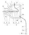
図1は本考案に係る光源装置の一例を示し、その光源となる高圧放電ランプ1は、石英ガラスで成る発光管2の中間部に形成された放電容器3内に、一対のタングステン電極5、5が1〜2mm程度の極間距離で互いに対向して配置されると共に、水銀と臭素等のハロゲンとアルゴンガス等の始動用ガスとが封入され、発光管2の両端側には、電極5とモリブデン箔で成る金属箔6とモリブデンワイヤで成る給電用ワイヤ7とを直列的に溶接した一対の電極アセンブリ4、4が夫々挿通されて、その発光管2の両端側をシュリンクシールによって気密に封止した封止部8R、8Lが形成されたショートアークタイプの高圧水銀蒸気放電ランプであって、発光管2の封止部8L側の端部を凹面反射鏡9のボトム部10にセメント等(図示せず)で固定して該反射鏡9内に取り付けられている。
FIG. 1 shows an example of a light source device according to the present invention. A high-
凹面反射鏡9は、高圧放電ランプ1の発光管2の封止部8Rから突出する給電用ワイヤ7に溶接されたリード線11を反射鏡9の外側に引き出すための配線孔12と、高圧放電ランプ1を冷却するための冷却エアを流通させる通風孔13とが穿設され、前面開口部にはその開口部を閉塞する透明カバー14が取り付けられている。
The concave reflecting
そして、凹面反射鏡9の外方には、高圧放電ランプ1の点灯装置(図示せず)によって電極5、5間に点灯電圧と高電圧パルスが印加される点灯始動時にその点灯装置により約2〜3秒間だけ点灯せられて波長355〜365nm程度の紫外光を出力する始動用光源20が設置され、該光源20から出力される紫外光が、紫外線透過率が高く、紫外線劣化のおそれもない耐熱温度600℃超の石英光ファイバ21で伝送されて高圧放電ランプ1Aの発光管2に形成された放電容器3に照射されるようになっている。
Further, outside the concave reflecting
始動用光源20は、パルスでの使用も可能なUV−LEDで成り、該LEDから出力される紫外光がレンズ23、24等の光学系で集光されて石英光ファイバ21の光入射端21aに入射されるようになっている。また、石英光ファイバ21は、その光出射端21bが、凹面反射鏡9の外方から該反射鏡に穿設された冷却エアの通風孔13に挿通されて、高圧放電ランプ1の放電容器3の外表面と対向する位置に配されている。これにより、石英光ファイバ21の光出射端21bから放電容器3に照射される紫外光で放電容器3内に封入された始動用ガスが励起されて、放電容器3内に対向して配置された電極5、5間の放電が促進され、高圧放電ランプ1の始動性能が向上する。
The starting
なお、石英光ファイバ21は、その光出射端21bを冷却エアの通風孔13に挿通せずに、図1に破線X1で示す如く、凹面反射鏡9に穿設されたリード線11の配線孔12に挿通してもよいし、破線X2で示す如く、凹面反射鏡9のボトム部10とそのボトム部に固定される高圧放電ランプ1の発光管2の端部との間に生ずる空隙等に挿通してもよい。また、実線と破線X1およびX2で示す石英光ファイバ21は、光出射端21bが発光管2の中間部に形成された放電容器3の外表面と対向する位置に配されているが、破線X3で示すように、発光管2の封止部8L側の片端面と対向する位置に配されている場合であってもよく、この場合は、石英光ファイバ21の光出射端21bから出射した紫外光が、発光管2の封止部8L内を透過して放電容器3内に照射される。また、石英光ファイバ21は、これを複数本束めてバンドルファイバとしたものであってもよい。
Incidentally, quartz
図2は本考案に係る光源装置の他の例を示す図である。本例の光源装置は、これを設置する液晶プロジェクタ内に、石英光ファイバ21を凹面反射鏡9の背面側に配線するスペースが存しない場合等に有用なものであり、始動用光源20から出力された紫外光を伝送する石英光ファイバ21の光出射端21bが、凹面反射鏡9の外方からその前面開口部を塞ぐ透明カバー14に穿設された貫通孔30に挿通されて、放電容器3の外表面と対向する位置に配された構成となっている点で図1の光源装置と相違し、その他の構成は、図1の光源装置と共通するので同一符号を付して詳細説明は省略する。
FIG. 2 is a view showing another example of the light source device according to the present invention. The light source device of this example is useful when there is no space for wiring the quartz
なお、石英光ファイバ21の光出射端21bを凹面反射鏡9の前面開口部側からその内方に向けて配置すると、該光出射端21bから出射した紫外光が高圧放電ランプ1の放電容器4に直接照射されるのみならず、その一部が凹面反射鏡9で反射されて高圧放電ランプ1の放電容器4に照射されるので、光出射端21bは、必ずしもその端面を放電容器4の外表面と正対させるように配置する必要はなく、凹面反射鏡9の内方に向けて配置されていればよい。
When the
本考案は、液晶プロジェクタ等の光源装置に用いられる高圧放電ランプの始動性能向上に資するものである。 The present invention contributes to improving the starting performance of a high-pressure discharge lamp used in a light source device such as a liquid crystal projector.
1…高圧放電ランプ
2…発光管
3…放電容器
5…電極
8R…封止部
8L…封止部
9…凹面反射鏡
20…始動用光源
21…石英光ファイバ
21b…石英光ファイバの光出射端
DESCRIPTION OF
DESCRIPTION OF
Claims (4)
Priority Applications (1)
| Application Number | Priority Date | Filing Date | Title |
|---|---|---|---|
| JP2007007603U JP3137962U (en) | 2007-10-03 | 2007-10-03 | Light source device |
Applications Claiming Priority (1)
| Application Number | Priority Date | Filing Date | Title |
|---|---|---|---|
| JP2007007603U JP3137962U (en) | 2007-10-03 | 2007-10-03 | Light source device |
Publications (1)
| Publication Number | Publication Date |
|---|---|
| JP3137962U true JP3137962U (en) | 2007-12-13 |
Family
ID=43288289
Family Applications (1)
| Application Number | Title | Priority Date | Filing Date |
|---|---|---|---|
| JP2007007603U Expired - Fee Related JP3137962U (en) | 2007-10-03 | 2007-10-03 | Light source device |
Country Status (1)
| Country | Link |
|---|---|
| JP (1) | JP3137962U (en) |
Cited By (2)
| Publication number | Priority date | Publication date | Assignee | Title |
|---|---|---|---|---|
| JP2011146275A (en) * | 2010-01-15 | 2011-07-28 | Iwasaki Electric Co Ltd | Light source device |
| WO2019176600A1 (en) * | 2018-03-13 | 2019-09-19 | フェニックス電機株式会社 | Light source device including discharge lamp, illuminating device, and determination method for discharge lamp |
-
2007
- 2007-10-03 JP JP2007007603U patent/JP3137962U/en not_active Expired - Fee Related
Cited By (2)
| Publication number | Priority date | Publication date | Assignee | Title |
|---|---|---|---|---|
| JP2011146275A (en) * | 2010-01-15 | 2011-07-28 | Iwasaki Electric Co Ltd | Light source device |
| WO2019176600A1 (en) * | 2018-03-13 | 2019-09-19 | フェニックス電機株式会社 | Light source device including discharge lamp, illuminating device, and determination method for discharge lamp |
Similar Documents
| Publication | Publication Date | Title |
|---|---|---|
| JP2008140614A (en) | High-pressure metal vapor discharge lamp and lighting fixture | |
| JP4626708B2 (en) | Light source device | |
| JP3137962U (en) | Light source device | |
| JP4572978B2 (en) | Light source device | |
| JP2006236919A (en) | High pressure metallic vapor discharge lamp and luminaire | |
| JP3137961U (en) | Light source device | |
| JP5126030B2 (en) | High pressure discharge lamp, lamp unit using the high pressure discharge lamp, and projector using the lamp unit | |
| JP4996146B2 (en) | High pressure discharge lamp and rear projector device | |
| WO2008023492A1 (en) | High-pressure discharge lamp manufacturing method, high-pressure discharge lamp, lamp unit, and projection image display | |
| JP2011222217A (en) | Optical apparatus | |
| JP5062269B2 (en) | Arc tube, light source device and projector | |
| JP2006236756A (en) | Short-arc type discharge lamp | |
| JP4048376B2 (en) | Discharge lamp and projector | |
| JP3665160B2 (en) | Discharge lamp, lamp device, lighting device, and liquid crystal projector | |
| JP2005228711A (en) | Optical apparatus | |
| JP5034755B2 (en) | Arc tube, light source device and projector | |
| JP2005077585A (en) | Lamp device and projector equipped therewith | |
| JP6671591B2 (en) | Short arc discharge lamp | |
| JP2007214069A (en) | High-pressure discharge lamp, lamp unit, image display device, and manufacturing method of high-pressure discharge lamp | |
| JP2011138713A (en) | Light source device and projector | |
| JP5640838B2 (en) | Discharge lamp device | |
| JP2008281628A (en) | Projector | |
| JPH087839A (en) | Low pressure discharge lamp device and optical reading device using the same | |
| KR100565226B1 (en) | Bulb of plasma lamp system | |
| JP2008204661A (en) | Fluorescent lamp, and luminaire |
Legal Events
| Date | Code | Title | Description |
|---|---|---|---|
| R150 | Certificate of patent or registration of utility model |
Free format text: JAPANESE INTERMEDIATE CODE: R150 |
|
| FPAY | Renewal fee payment (event date is renewal date of database) |
Free format text: PAYMENT UNTIL: 20101121 Year of fee payment: 3 |
|
| FPAY | Renewal fee payment (event date is renewal date of database) |
Free format text: PAYMENT UNTIL: 20101121 Year of fee payment: 3 |
|
| S531 | Written request for registration of change of domicile |
Free format text: JAPANESE INTERMEDIATE CODE: R323531 |
|
| R350 | Written notification of registration of transfer |
Free format text: JAPANESE INTERMEDIATE CODE: R350 |
|
| FPAY | Renewal fee payment (event date is renewal date of database) |
Free format text: PAYMENT UNTIL: 20101121 Year of fee payment: 3 |
|
| FPAY | Renewal fee payment (event date is renewal date of database) |
Free format text: PAYMENT UNTIL: 20111121 Year of fee payment: 4 |
|
| LAPS | Cancellation because of no payment of annual fees |