JP3126002U - Card connector - Google Patents
Card connector Download PDFInfo
- Publication number
- JP3126002U JP3126002U JP2006005390U JP2006005390U JP3126002U JP 3126002 U JP3126002 U JP 3126002U JP 2006005390 U JP2006005390 U JP 2006005390U JP 2006005390 U JP2006005390 U JP 2006005390U JP 3126002 U JP3126002 U JP 3126002U
- Authority
- JP
- Japan
- Prior art keywords
- card
- card connector
- insulating housing
- erroneous insertion
- accommodation space
- Prior art date
- Legal status (The legal status is an assumption and is not a legal conclusion. Google has not performed a legal analysis and makes no representation as to the accuracy of the status listed.)
- Expired - Fee Related
Links
Images


Landscapes
- Coupling Device And Connection With Printed Circuit (AREA)
- Details Of Connecting Devices For Male And Female Coupling (AREA)
Abstract
【課題】初期状態に回復することを確保できる誤挿着防止機構を有するカード用コネクタを提供する。
【解決手段】本考案のカード用コネクタは、サイズの大きいカードを収容するための挿入口を有する収容空間が形成される絶縁ハウジングと、前記絶縁ハウジングにそれぞれ装着され、前記収容空間へそれぞれ延出される第1導電端子及び第2導電端子と、前記サイズの大きいカードの挿入口を覆い、前記収容空間へ延出するように形成されるサイズの小さいカードをガイドするための案内部材が設けられる誤挿着防止機構と、天板に受入空間が形成され、前記絶縁ハウジングに取付けられるシールドとを含み、サイズの異なるカードを収容できるカード用コネクタにおいて、前記シールドの受入空間に収容される弾性部材を有し、該弾性部材は前記誤挿着防止機構に弾性的な作用力を加える。
【選択図】図1A card connector having an erroneous insertion prevention mechanism capable of ensuring recovery to an initial state is provided.
A card connector according to the present invention includes an insulating housing having a receiving space having an insertion slot for receiving a large-sized card, and an insulating housing formed in the insulating housing and extending to the receiving space. A first conductive terminal and a second conductive terminal, and a guide member for guiding a small card formed so as to cover the insertion slot of the large card and extend into the accommodating space. An elastic member accommodated in the receiving space of the shield in a card connector that includes an insertion preventing mechanism and a receiving space formed in the top plate and includes a shield attached to the insulating housing and can accommodate cards of different sizes. And the elastic member applies an elastic force to the erroneous insertion preventing mechanism.
[Selection] Figure 1
Description
本考案はカード用コネクタに関し、特に誤挿着防止機構を有するカード用コネクタに関するものである。 The present invention relates to a card connector, and more particularly to a card connector having an erroneous insertion prevention mechanism.
携帯電話、デジタルカメラ、PDA(Personal Digital Assistance)などの電子機器の増設記録装置としてカード用コネクタが一般的に使用されている。このカード用コネクタの記憶媒体としては、SD(Super Density, secure digital)カード、MMC (Multimedia Card)カード、SM (Smart Media)カード、MS (Memory Stick)カード、MSDuo(Memory Stick Duo)カード、XD (XD−picture)カード等が広く使用されるようになってきている。 A card connector is generally used as an expansion recording device for electronic devices such as mobile phones, digital cameras, and PDAs (Personal Digital Assistance). The storage medium of this card connector includes SD (Super Density, secure digital) card, MMC (Multimedia Card) card, SM (Smart Media) card, MS (Memory Stick) card, MS Duo (Memory Stick Duo), (XD-picture) cards and the like have been widely used.
前記各種のカードのサイズが異なるので、カード用コネクタのサイズが異なることが必要になり、各種カード用コネクタは一種のカードしか挿着することができず、電子機器の実装面積を大きくして、電子機器の小型化に不利になっている。
その後、多種カードを実装するカード用コネクタが考案され、これは、例えば、特許文献1に開示されたようなカード用コネクタであり、サイズの異なるカードを収容する収容溝が形成され、各カードが収容溝に対応して挿着される。
Thereafter, a card connector for mounting a variety of cards has been devised, which is, for example, a card connector as disclosed in Patent Document 1, in which receiving grooves for receiving cards of different sizes are formed. It is inserted corresponding to the receiving groove.
しかしながら、前記特許文献1に開示されたカード用コネクタは、多種の収容溝が形成されるので、各収容溝内に誤挿着防止機構を配置することが必要になる。しかし、従来のカード用コネクタは、カードを他の収容溝内に誤挿着する際に、たとえ誤挿着されたカードを排出しても、誤挿着防止機構が損傷され、初期状態に回復しない恐れがある。そこで、従来の技術の不足を改善したカード用コネクタを開発する必要がある。 However, since the card connector disclosed in Patent Document 1 has various housing grooves, it is necessary to dispose an erroneous insertion preventing mechanism in each housing groove. However, the conventional card connector recovers to the initial state when the card is misinserted into another receiving groove, even if the misinserted card is ejected, the misinsertion prevention mechanism is damaged. There is a fear of not. Therefore, it is necessary to develop a card connector that improves the shortage of conventional techniques.
本考案は、初期状態に回復することを確保できる誤挿着防止機構を有するカード用コネクタを提供することを目的とする。 An object of the present invention is to provide a card connector having an erroneous insertion prevention mechanism that can ensure recovery to an initial state.
本考案のカード用コネクタは、サイズの大きいカードを収容するための挿入口を有する収容空間が形成される絶縁ハウジングと、
前記絶縁ハウジングにそれぞれ装着され、前記収容空間へそれぞれ延出される第1導電端子及び第2導電端子と、
前記サイズの大きいカードの挿入口を覆い、前記収容空間へ延出するように形成されるサイズの小さいカードをガイドするための案内部材が設けられる誤挿着防止機構と、
天板に受入空間が形成され、前記絶縁ハウジングに取付けられるシールドと
を含み、サイズの異なるカードを収容できるカード用コネクタにおいて、
前記シールドの受入空間に収容される弾性部材を有し、該弾性部材は前記誤挿着防止機構に弾性的な作用力を加えることを特徴とする。
The card connector of the present invention is an insulating housing in which an accommodation space having an insertion slot for accommodating a large card is formed;
A first conductive terminal and a second conductive terminal respectively mounted on the insulating housing and extending to the accommodation space;
An erroneous insertion prevention mechanism provided with a guide member for guiding a small card formed so as to cover the insertion slot of the large card and extend to the accommodation space;
In the card connector, the receiving space is formed in the top plate and includes a shield attached to the insulating housing, and can accommodate cards of different sizes.
It has an elastic member stored in the receiving space of the shield, and the elastic member applies an elastic acting force to the erroneous insertion preventing mechanism.
また、本考案のカード用コネクタは、サイズの大きいカードを収容するための挿入口を有する収容空間が形成される絶縁ハウジングと、
前記絶縁ハウジングにそれぞれ装着され、前記収容空間へそれぞれ延出される第1導電端子及び第2導電端子と、
前記サイズの大きいカードの挿入口を覆い、前記収容空間へ延出するように形成されるサイズの小さいカードをガイドするための案内部材が設けられる誤挿着防止機構と
を含み、サイズの異なるカードを収容できるカード用コネクタにおいて、
前記誤挿着防止機構を係合するための係合部材を有し、サイズの大きいカードを前記収容空間に挿入する際に前記係合部材が回転できることを特徴とする。
In addition, the card connector of the present invention includes an insulating housing in which an accommodation space having an insertion port for accommodating a large card is formed;
A first conductive terminal and a second conductive terminal respectively mounted on the insulating housing and extending to the accommodation space;
An erroneous insertion preventing mechanism provided with a guide member for guiding a small card formed so as to cover the insertion slot of the large card and extend into the accommodating space, and having a different size In the card connector that can accommodate
It has an engaging member for engaging with the erroneous insertion preventing mechanism, and the engaging member can rotate when a large-sized card is inserted into the receiving space.
また、本考案のカード用コネクタは、サイズの大きいカードを収容するための挿入口を有する収容空間が形成される絶縁ハウジングと、
前記絶縁ハウジングにそれぞれ装着され、前記収容空間へそれぞれ延出される第1導電端子及び第2導電端子と、
前記サイズの大きいカードの挿入口を覆い、前記収容空間へ延出するように形成されるサイズの小さいカードをガイドするための案内部材と、サイズの小さいカードを挿入するための挿着口とが設けられる誤挿着防止機構と
を含み、サイズの異なるカードを収容できるカード用コネクタにおいて、
前記挿着口を覆っていて、弾性部材を有するシェルを含み、サイズの小さいカードが収容空間に排出される際に、該弾性部材は前記シェルに弾性的な作用力を加えることを特徴とする。
In addition, the card connector of the present invention includes an insulating housing in which an accommodation space having an insertion port for accommodating a large card is formed;
A first conductive terminal and a second conductive terminal respectively mounted on the insulating housing and extending to the accommodation space;
A guide member for guiding a small card formed so as to cover the insertion slot of the large card and extending to the accommodation space; and an insertion slot for inserting the small card. A card connector that can accommodate cards of different sizes,
The shell includes an elastic member covering the insertion slot, and the elastic member applies an elastic acting force to the shell when a small-sized card is discharged into the receiving space. .
従来技術に比べ、本考案は以下の利点を有する。本考案のカード用コネクタは弾性部材によって、カードが排出される際に、誤挿着防止機構に弾性的な作用力を加え、誤挿着防止機構が損傷され、初期状態に回復しない恐れが防止される。 Compared with the prior art, the present invention has the following advantages. The card connector of the present invention uses an elastic member to apply an elastic action force to the erroneous insertion prevention mechanism when the card is ejected, preventing the erroneous insertion prevention mechanism from being damaged and not recovering to the initial state. Is done.
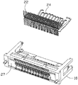
以下、図1〜図10を参照すると、本考案のカード用コネクタの好ましい実施形態について、添付図面を参照して説明する。該カード用コネクタ100は、絶縁ハウジング10と、カードの導電パッドに接続するための第1導電端子22と、第2導電端子24と、絶縁ハウジング10に組み付けられるシールド28と、誤挿着防止機構40と、シェル56と係合部材60と、を含む。
1 to 10, a preferred embodiment of a card connector according to the present invention will be described with reference to the accompanying drawings. The
図1乃至図5を参照すると、前記絶縁ハウジング10は、略矩形状を呈し、相対した天板12及び底板14と、天板12と底板14とを連接する両側壁16及び後壁27と、天板12と底板14と両側壁16と後壁27とからなる収容空間18と、を含む。前記天板12に開口13が形成され、底板14に収容口142及び凹み部15が形成され、側壁16の先端に切欠部17が形成される。前記第1導電端子22は、サイズの大きいカード(図示せず)の導電パッドに接続し、一端が後壁27を貫通して回路基板(図示せず)に半田付けされ、他端が収容空間18に延在している。第2導電端子24は、サイズの小さいカード300の導電パッドに接続し、一端が底板14を貫通し手回路基板に半田付けされ、他端が収容空間18に延在している。
Referring to FIGS. 1 to 5, the
前記シールド28は、絶縁ハウジング10に対応した天板30と、底板32と、天板30と底板32とを連接する側板34とを含み、その天板30には、分離可能な分離板301を有する。前記分離板301は、上向きに突設して形成される受入空間302と、分離板301の頂壁から受入空間302向きに突出するように形成される保持片303と、が形成される。前記受入空間302内にスプリング304を収容し、該スプリング304は、一端が前記保持片303に保持され、他端が誤挿着防止機構40に固持される。
The
天板30には、前記絶縁ハウジング10の開口13に連通している開口36と、該開口36の両側に配置される弾性片37とが形成され、前記弾性片37の末端部371は、前記分離板31に形成される突起305に係合するために上向きに延在している。また、前記側板34に押圧片38が形成される。
The
図6乃至図9を参照して、誤挿着防止機構40は、絶縁ハウジング10の前側に取付けられ、シャッターとしてサイズの大きいカードの挿入口19を覆い、平板状の主体部44と、主体部44の両側に枢支軸42と、サイズの小さいカード300を挿入するために主体部44に形成される挿入口46と、を含む。前記挿着口46は、前記収容空間18に連通して挿入口19に重なり、また、主体部44の後壁50の両側に、前記シールド28の弾性片37に当接する凸塊51がそれぞれ形成される。
Referring to FIGS. 6 to 9, the erroneous
主体部44の後壁50から、サイズの小さいカード300をガイドするためにカードの挿入方向に沿って延出するように形成される一対の案内部材48が設けられ、案内部材48が挿着口46の両側に配置される。案内部材48は、末端に位置決め部54が形成され、絶縁ハウジング10の天板12に近接した頂壁481に前記スプリング304を保持するためのガイド溝4811が形成され、絶縁ハウジング10の底板14に近接した底壁482に、絶縁ハウジング10の収容口142に収容される凸部4821が形成される。前記スプリング304により、案内部材48に弾性的な作用力が加えられる。また、サイズの小さいカード300を支持するために、主体部44の後壁50から収容空間18向きに延在するように形成される支持板52は前記挿着口46の下側に位置し、絶縁ハウジング10の凹み部15に収容される。
A pair of
前記シェル56は、金属板からなり、両側に形成される軸部58にスプリング581を被覆し、該スプリング581は、一端が誤挿着防止機構40の主体部44に保持され、他端がシェル56に保持される。これにより、該シェル56が誤挿着防止機構40の後壁50に回転可能に実装され、挿着口46を覆っている。
The
前記係合部材60は、側壁16の先端に形成される切欠部17に回転可能に取付けられ、シールド28の押圧片38に押圧される。該係合部材60は、枢支部62と、サイズの大きいカードに当接される押圧面64と、誤挿着防止機構40をロックするための係合部66とを有する。
The
カードをまだ挿入しない際に、誤挿着防止機構40が、サイズの大きいカードの挿入口19を覆っていて、前記誤挿着防止機構40に取付けられるシェル56は、サイズの小さいカード300の挿着口46を覆っている。サイズの大きいカードが挿入される際に、該カードの両側端が前記係合部材60の押圧面64に当接すると、係合部材60を枢支部62を軸として外方向きに回転させ、これによって、誤挿着防止機構40をロックするための係合部66も外方向きに回転するので、誤挿着防止機構40と係合部66とのロックが解除される。誤挿着防止機構40は、サイズの大きいカードの挿入に従って上向きに回転し、絶縁ハウジング10の開口13とシールド28の開口36を貫通して水平位置に到達する。この時、サイズの大きいカードが第1導電端子22に電気的に接続し、シェル56がサイズの小さいカード300の挿着口46を覆う閉鎖状態になる。
When the card is not yet inserted, the erroneous
サイズの大きいカードが排出された際に、前記シールド28の分離板301に取付けられるスプリング304の一端が誤挿着防止機構40の案内部材48に当接し、シールド28の弾性片37が誤挿着防止機構40の凸塊51に当接し、押圧片38が係合部材60に押圧し、これらによって、誤挿着防止機構40と係合部材60を初期状態に回復させる。
When a large card is ejected, one end of the
図10を参照すると、サイズの小さいカード300が挿着口46に挿入する際に、横幅が小さいことで係合部材60に当接せず、直ちにシェル56を押圧して上向きに回転させ、前記案内部材48と支持板52により収容空間18に収容して支持され、第2導電端子24との電気的な接続を達成している。該サイズの小さいカード300が排出される際に、前記スプリング581の弾性力によって、前記シェル56を初期状態に回復させる。
Referring to FIG. 10, when the
サイズの小さいカード300の挿入力が大きすぎる際に、前記案内部材48は、凸塊4821が絶縁ハウジング10の収容口142に収容されることによって、前方と左右方向への移動が制限され、さらに、サイズの小さいカードの挿入をガイドすることが確保される。
When the insertion force of the small-
以上本考案について好ましい実施の形態を参照して詳細に説明したが、実施形態はあくまでも例示的なものであり、これらに限定されるものではない。また、本考案に基づきなし得る細部の修正或は変更など、いずれも本考案の請求範囲に属するものである。 Although the present invention has been described in detail with reference to the preferred embodiments, the embodiments are merely illustrative and are not limited thereto. Further, any modification or change in details that can be made based on the present invention falls within the scope of the claims of the present invention.
100 カード用コネクタ
10 絶縁ハウジング
12、30 天板
13、36 開口
14、32 底板
142 収容口
15 凹み部
16 側壁
17 切欠部
18 収容空間
19 挿入口
22 第1導電端子
24 第2導電端子
27、50 後壁
28 シールド
300 サイズの小さいカード
301 分離板
302 受入空間
303 保持片
304、581 スプリング(弾性部材)
305 突起
34 側板
37 弾性片
38 押圧片
40 誤挿着防止機構
42 枢支軸
44 主体部
46 挿着口
48 案内部材
481 頂壁
4811 ガイド溝
482 底壁
4821 凸部
50 後壁
52 支持板
54 位置決め部
56 シェル
58 軸部
60 係合部材
62 枢支部
64 押圧面
66 係合部
DESCRIPTION OF
305
Claims (9)
前記絶縁ハウジングにそれぞれ装着され、前記収容空間へそれぞれ延出される第1導電端子及び第2導電端子と、
前記サイズの大きいカードの挿入口を覆い、前記収容空間へ延出するように形成されるサイズの小さいカードをガイドするための案内部材が設けられる誤挿着防止機構と、
天板に受入空間が形成され、前記絶縁ハウジングに取付けられるシールドと
を含み、サイズの異なるカードを収容できるカード用コネクタにおいて、
前記シールドの受入空間に収容される弾性部材を有し、該弾性部材は前記誤挿着防止機構に弾性的な作用力を加えることを特徴とするカード用コネクタ。 An insulating housing in which an accommodation space having an insertion slot for accommodating a large card is formed;
A first conductive terminal and a second conductive terminal respectively mounted on the insulating housing and extending to the accommodation space;
An erroneous insertion prevention mechanism provided with a guide member for guiding a small card formed so as to cover the insertion slot of the large card and extend to the accommodation space;
In the card connector, the receiving space is formed in the top plate and includes a shield attached to the insulating housing, and can accommodate cards of different sizes.
A card connector comprising an elastic member accommodated in a receiving space of the shield, and the elastic member applies an elastic acting force to the erroneous insertion preventing mechanism.
前記絶縁ハウジングにそれぞれ装着され、前記収容空間へそれぞれ延出される第1導電端子及び第2導電端子と、
前記サイズの大きいカードの挿入口を覆い、前記収容空間へ延出するように形成されるサイズの小さいカードをガイドするための案内部材が設けられる誤挿着防止機構と
を含み、サイズの異なるカードを収容できるカード用コネクタにおいて、
前記誤挿着防止機構を係合するための係合部材を有し、サイズの大きいカードを前記収容空間に挿入する際に前記係合部材が回転できることを特徴とするカード用コネクタ。 An insulating housing in which an accommodation space having an insertion slot for accommodating a large card is formed;
A first conductive terminal and a second conductive terminal respectively mounted on the insulating housing and extending to the accommodation space;
An erroneous insertion preventing mechanism provided with a guide member for guiding a small card formed so as to cover the insertion slot of the large card and extend into the accommodating space, and having a different size In the card connector that can accommodate
A card connector comprising an engaging member for engaging the erroneous insertion preventing mechanism, wherein the engaging member can rotate when a large-sized card is inserted into the receiving space.
前記絶縁ハウジングにそれぞれ装着され、前記収容空間へそれぞれ延出される第1導電端子及び第2導電端子と、
前記サイズの大きいカードの挿入口を覆い、前記収容空間へ延出するように形成されるサイズの小さいカードをガイドするための案内部材と、サイズの小さいカードを挿入するための挿着口とが設けられる誤挿着防止機構と
を含み、サイズの異なるカードを収容できるカード用コネクタにおいて、
前記挿着口を覆っていて、弾性部材を有するシェルを含み、サイズの小さいカードが収容空間に排出される際に、該弾性部材は前記シェルに弾性的な作用力を加えることを特徴とするカード用コネクタ。 An insulating housing in which an accommodation space having an insertion slot for accommodating a large card is formed;
A first conductive terminal and a second conductive terminal respectively mounted on the insulating housing and extending to the accommodation space;
A guide member for guiding a small card formed so as to cover the insertion slot of the large card and extending to the accommodation space; and an insertion slot for inserting the small card. A card connector that can accommodate cards of different sizes,
The shell includes an elastic member covering the insertion slot, and the elastic member applies an elastic acting force to the shell when a small-sized card is discharged into the receiving space. Card connector.
Applications Claiming Priority (1)
| Application Number | Priority Date | Filing Date | Title |
|---|---|---|---|
| TW94215641U TWM289546U (en) | 2005-09-12 | 2005-09-12 | Electrical card connector |
Publications (1)
| Publication Number | Publication Date |
|---|---|
| JP3126002U true JP3126002U (en) | 2006-10-12 |
Family
ID=37564824
Family Applications (1)
| Application Number | Title | Priority Date | Filing Date |
|---|---|---|---|
| JP2006005390U Expired - Fee Related JP3126002U (en) | 2005-09-12 | 2006-07-05 | Card connector |
Country Status (2)
| Country | Link |
|---|---|
| JP (1) | JP3126002U (en) |
| TW (1) | TWM289546U (en) |
-
2005
- 2005-09-12 TW TW94215641U patent/TWM289546U/en not_active IP Right Cessation
-
2006
- 2006-07-05 JP JP2006005390U patent/JP3126002U/en not_active Expired - Fee Related
Also Published As
| Publication number | Publication date |
|---|---|
| TWM289546U (en) | 2006-04-11 |
Similar Documents
| Publication | Publication Date | Title |
|---|---|---|
| KR100682570B1 (en) | Adaptor for memory card | |
| US7112095B2 (en) | Card connector | |
| US7491076B2 (en) | Rotatable memory card with improved locking mechanism | |
| KR100717739B1 (en) | Dual card type connector of mobile phone | |
| US7083440B2 (en) | Card connector | |
| JP2016134358A (en) | Card tray and card connector | |
| CN100530829C (en) | Memory card connector | |
| KR100717740B1 (en) | Dual card type connector of mobile phone | |
| JP3126002U (en) | Card connector | |
| TWM324876U (en) | Electrical card connector | |
| JP5480003B2 (en) | Tray type card connector | |
| JP4268059B2 (en) | Card connector device | |
| KR101361740B1 (en) | Dual card type socket and assembly method thereof | |
| JP5663374B2 (en) | Tray type card connector | |
| JP3140116U (en) | Memory card connector | |
| JP2004063255A (en) | Slot connector | |
| KR101076652B1 (en) | Connector and detection switch | |
| JP5480002B2 (en) | Tray type card connector | |
| US20090275238A1 (en) | Electrical card connector with a metal retention mechanism | |
| JP2010102830A (en) | Connector for card | |
| JP2004311123A (en) | Connector device for card | |
| KR20070098313A (en) | Grounding structure of dual card type connector of mobile phone | |
| KR200419254Y1 (en) | Dual card type connector of mobile phone | |
| TWM537737U (en) | Electrical card connector | |
| KR200419473Y1 (en) | Grounding structure of Dual card type connector of mobile phone |
Legal Events
| Date | Code | Title | Description |
|---|---|---|---|
| A521 | Written amendment |
Effective date: 20060802 Free format text: JAPANESE INTERMEDIATE CODE: A523 |
|
| LAPS | Cancellation because of no payment of annual fees |