JP3121820U - Portable terminal having dual display module structure - Google Patents
Portable terminal having dual display module structure Download PDFInfo
- Publication number
- JP3121820U JP3121820U JP2006000158U JP2006000158U JP3121820U JP 3121820 U JP3121820 U JP 3121820U JP 2006000158 U JP2006000158 U JP 2006000158U JP 2006000158 U JP2006000158 U JP 2006000158U JP 3121820 U JP3121820 U JP 3121820U
- Authority
- JP
- Japan
- Prior art keywords
- display panel
- hinge
- piece
- portable terminal
- wiring
- Prior art date
- Legal status (The legal status is an assumption and is not a legal conclusion. Google has not performed a legal analysis and makes no representation as to the accuracy of the status listed.)
- Expired - Fee Related
Links
Images


Classifications
-
- H—ELECTRICITY
- H04—ELECTRIC COMMUNICATION TECHNIQUE
- H04M—TELEPHONIC COMMUNICATION
- H04M1/00—Substation equipment, e.g. for use by subscribers
- H04M1/02—Constructional features of telephone sets
- H04M1/0202—Portable telephone sets, e.g. cordless phones, mobile phones or bar type handsets
- H04M1/026—Details of the structure or mounting of specific components
- H04M1/0266—Details of the structure or mounting of specific components for a display module assembly
-
- G—PHYSICS
- G06—COMPUTING; CALCULATING OR COUNTING
- G06F—ELECTRIC DIGITAL DATA PROCESSING
- G06F1/00—Details not covered by groups G06F3/00 - G06F13/00 and G06F21/00
- G06F1/16—Constructional details or arrangements
- G06F1/1613—Constructional details or arrangements for portable computers
- G06F1/1615—Constructional details or arrangements for portable computers with several enclosures having relative motions, each enclosure supporting at least one I/O or computing function
- G06F1/1616—Constructional details or arrangements for portable computers with several enclosures having relative motions, each enclosure supporting at least one I/O or computing function with folding flat displays, e.g. laptop computers or notebooks having a clamshell configuration, with body parts pivoting to an open position around an axis parallel to the plane they define in closed position
-
- G—PHYSICS
- G06—COMPUTING; CALCULATING OR COUNTING
- G06F—ELECTRIC DIGITAL DATA PROCESSING
- G06F1/00—Details not covered by groups G06F3/00 - G06F13/00 and G06F21/00
- G06F1/16—Constructional details or arrangements
- G06F1/1613—Constructional details or arrangements for portable computers
- G06F1/1633—Constructional details or arrangements of portable computers not specific to the type of enclosures covered by groups G06F1/1615 - G06F1/1626
- G06F1/1637—Details related to the display arrangement, including those related to the mounting of the display in the housing
- G06F1/1641—Details related to the display arrangement, including those related to the mounting of the display in the housing the display being formed by a plurality of foldable display components
-
- G—PHYSICS
- G06—COMPUTING; CALCULATING OR COUNTING
- G06F—ELECTRIC DIGITAL DATA PROCESSING
- G06F1/00—Details not covered by groups G06F3/00 - G06F13/00 and G06F21/00
- G06F1/16—Constructional details or arrangements
- G06F1/1613—Constructional details or arrangements for portable computers
- G06F1/1633—Constructional details or arrangements of portable computers not specific to the type of enclosures covered by groups G06F1/1615 - G06F1/1626
- G06F1/1675—Miscellaneous details related to the relative movement between the different enclosures or enclosure parts
- G06F1/1683—Miscellaneous details related to the relative movement between the different enclosures or enclosure parts for the transmission of signal or power between the different housings, e.g. details of wired or wireless communication, passage of cabling
-
- H—ELECTRICITY
- H04—ELECTRIC COMMUNICATION TECHNIQUE
- H04M—TELEPHONIC COMMUNICATION
- H04M2250/00—Details of telephonic subscriber devices
- H04M2250/16—Details of telephonic subscriber devices including more than one display unit
Abstract
【課題】携帯用の端末機に設けられた複数のパネルを整合的に結合させることで、歪みのない一つの画面を表示可能にする携帯用の端末機を提供する。
【解決手段】本考案に係る携帯用の端末機は、第1映像が表示されるメインディスプレイパネル部10と、第2映像が表示されるサブディスプレイパネル部20と、サブディスプレイパネル部20をメインディスプレイパネル部10に回転可能に固定するヒンジ連結部と、ヒンジ連結部と対向して設けられ、メイン及びサブディスプレイパネル部10、20を電気的に連結させるための配線が挿入される配線連結部とを備えている。
【選択図】 図1A portable terminal capable of displaying a single screen without distortion by consistently coupling a plurality of panels provided in the portable terminal.
A portable terminal according to the present invention mainly includes a main display panel unit 10 for displaying a first video, a sub display panel unit 20 for displaying a second video, and a sub display panel unit 20. A hinge connecting portion that is rotatably fixed to the display panel portion 10 and a wiring connecting portion that is provided facing the hinge connecting portion and into which wiring for electrically connecting the main and sub display panel portions 10 and 20 is inserted. And.
[Selection] Figure 1
Description
本考案は携帯用の端末機に関し、より詳しくは、携帯用の端末機のメインディスプレイパネル部及びサブディスプレイパネル部を整合的に結合させることで、歪みのない一つの大画面を表示可能な携帯用の端末機のデュアルディスプレイモジュール構造に関する。 The present invention relates to a portable terminal, and more particularly, a portable terminal capable of displaying a single large screen without distortion by consistently coupling a main display panel and a sub display panel of the portable terminal. The present invention relates to a dual display module structure of a mobile terminal.
一般に、携帯用の端末機とは、デジタルフォーン(Digital phone)、セルラーフォーン(Cellular phone)、PCS(Personal Communications Service)フォーン等のような移動通信端末機、又はPDA(Personal Digital Assistant)及び小型のノートブック等のように携帯可能なデジタル端末機を称する装置であり、通常、これは、無線通信リンクと連動してユーザに音声及び映像情報等の様々なデジタルコンテンツを提供する機能を行う。 In general, a portable terminal is a mobile communication terminal such as a digital phone, a cellular phone, a PCS (Personal Communications Service) phone, or a PDA (Personal Digital Assistant) and a small phone. A device called a portable digital terminal such as a notebook or the like, and usually performs a function of providing various digital contents such as audio and video information to a user in conjunction with a wireless communication link.
このような携帯用の端末機は、携帯性の極大化のために、高感度、小型化及び軽量化を目指して発展しつつあるが、この傾向は、携帯用の端末機の代表としての移動通信端末機の発展過程を調べれば分かる。 In order to maximize portability, such portable terminals are being developed with the aim of achieving high sensitivity, miniaturization, and weight reduction. This can be understood by examining the development process of communication terminals.
即ち、初期の移動通信端末機のタイプであるバー(Bar)型及びフリップ(Flip)型の端末機は、その形状の拡張が不可能で大きくて重いため、現在ではほとんど用いられていなく、小型及び軽量でありながらその形状の拡張が可能なスライドフォルダ型及びフォルダ型(折り畳み型)の端末機が用いられている(特許文献1)。
最近では、無線データサービスが大衆化するにつれて、携帯用の端末機のマルチメディアコンテンツの提供機能は、その携帯用の端末機が元々有する機能(移動通信端末機の場合は通話機能、PDAの場合はデータの入力機能)より一層重要となっている趨勢である。携帯用の端末機が、このようなマルチメディアコンテンツの機能、特に、映像コンテンツの機能を有効に行うためには、通信網から受信した映像コンテンツをディスプレイパネルを介してどれほど完璧に表示することができるかが重要な要素となる。 Recently, as wireless data services have become popular, the multimedia content provision function of portable terminals is the function originally possessed by portable terminals (call function for mobile communication terminals, PDA) Is a trend that is even more important than the data input function. In order for a portable terminal to effectively perform such multimedia content functions, particularly video content functions, it is necessary to display the video content received from the communication network through the display panel. Whether it can be done is an important factor.
しかし、上述したように、携帯用の端末機の携帯性を高めるために、ディスプレイパネルの大きさは限定されなければならない。このため、従来のディスプレイパネルの上においては、良質の映像コンテンツを表示し難いという問題があった。 However, as described above, the size of the display panel must be limited in order to improve the portability of the portable terminal. For this reason, there has been a problem that it is difficult to display high-quality video content on a conventional display panel.
本考案の目的は、複数のパネルを結合して一つの拡張した画面が具現できる携帯用の端末機を提供することにある。 An object of the present invention is to provide a portable terminal capable of realizing a single expanded screen by combining a plurality of panels.
本考案の他の目的は、携帯用の端末機の複数のパネルがより整合的に結合されるようにするヒンジ構造を提供することにある。 Another object of the present invention is to provide a hinge structure that allows a plurality of panels of a portable terminal to be coupled in a more consistent manner.
前記のような目的を達成するために、本考案の一実施形態に係る携帯用の端末機は、第1映像が表示される第1ディスプレイパネル部と、第2映像が表示される第2ディスプレイパネル部と、前記第2ディスプレイパネル部を前記第1ディスプレイパネル部に回転可能に固定するヒンジ連結部と、前記ヒンジ連結部と対向して設けられ、前記第1及び第2ディスプレイパネル部を電気的に連結するための配線が挿入される配線連結部とを備えている。 In order to achieve the above object, a portable terminal according to an embodiment of the present invention includes a first display panel unit that displays a first image and a second display that displays a second image. A panel portion; a hinge connecting portion for rotatably fixing the second display panel portion to the first display panel portion; and a hinge connecting portion provided opposite to the hinge connecting portion, wherein the first and second display panel portions are electrically connected. And a wiring connecting portion into which wiring for connecting them is inserted.
本考案の一実施形態によると、ヒンジ連結部は、前記第1ディスプレイパネル部に形成され、切開片及び左右の両側面が開放されている連結片からなる第1ヒンジ連結部と、前記第2ディスプレイパネル部に形成され、一側面が前記第1ヒンジ連結部の一側面と連通するように開放される第2ヒンジ連結部と、前記第1及び第2ヒンジ連結部に挿入されるヒンジ軸とを包含する。 According to an embodiment of the present invention, the hinge connection part is formed on the first display panel part, and includes a first hinge connection part formed of an incision piece and a connection piece having left and right side surfaces open, and the second hinge connection part. A second hinge connection part formed on the display panel part and opened so that one side surface thereof communicates with one side surface of the first hinge connection part; and a hinge shaft inserted into the first and second hinge connection parts; Is included.
ここで、ヒンジ軸は、前記第1ヒンジ連結部に挿入される第1ヒンジ片及び前記第2ヒンジ連結部に挿入される第2ヒンジ片からなり、前記第1ヒンジ片の直径が前記第2ヒンジ片の直径より大きく形成される。 The hinge shaft includes a first hinge piece inserted into the first hinge connection part and a second hinge piece inserted into the second hinge connection part, and the diameter of the first hinge piece is the second hinge piece. It is formed larger than the diameter of the hinge piece.
本考案の一実施形態によると、前記配線連結部は、前記第1ディスプレイパネル部に突出するように形成される連結片、及び前記第1ディスプレイパネル部の内側へ凹んでいる受け片を含む第1配線連結部と、前記第2ディスプレイパネル部に形成され、前記第1配線連結部の前記受け片に回転可能に装着される第2配線連結部とを含んでいる。 According to an embodiment of the present invention, the wiring connection part includes a connection piece formed to protrude from the first display panel part, and a receiving piece recessed inward of the first display panel part. 1 wiring connection part and the 2nd wiring connection part which is formed in the said 2nd display panel part, and is rotatably mounted | worn with the said receiving piece of the said 1st wiring connection part.
ここで、前記第1配線連結部の前記連結片は、上部が前記第1ディスプレイパネル部の上へ突出し、下部は前記第1ディスプレイパネル部の内部へ入り込み、突出した上部の一側面は閉鎖され、上部の他側面は開放され、下部の左右の両側面は開放される。 Here, an upper portion of the connection piece of the first wiring connection portion protrudes above the first display panel portion, a lower portion enters the inside of the first display panel portion, and one side surface of the protruded upper portion is closed. The other side of the upper part is opened, and the left and right side faces of the lower part are opened.
そして、前記第2配線連結部は円筒状からなり、一側面が前記連結片の開放されている下部の一側面と連通するように開放され、この一側面には係合突出部が円周方向に突出して形成され、前記係合突出部は、前記第1配線連結部の連結片に回転可能に結合される。 The second wiring connecting portion is formed in a cylindrical shape, and one side surface is opened so as to communicate with one side surface of the lower portion where the connecting piece is opened. The engaging protrusion is rotatably coupled to the connecting piece of the first wiring connecting portion.
また、前記第1及び第2ディスプレイパネルを電気的に連結するための配線は、前記第1配線連結部の連結片及び第2配線連結部を貫通するように設けられる。 In addition, a wiring for electrically connecting the first and second display panels is provided so as to penetrate the connection piece of the first wiring connection portion and the second wiring connection portion.
前記のような本考案は、メインディスプレイパネル部及びサブディスプレイパネル部からなるデュアルディスプレイモジュール構造において、相対的に回転可能に結合されたメインディスプレイパネル部とサブディスプレイパネル部との間により精密な整合ヒンジ構造を提供することで、より鮮明であり、かつ高画質な映像コンテンツの表示機能が具現できる効果がある。 The present invention as described above is a dual display module structure composed of a main display panel part and a sub display panel part, and a more precise alignment between the main display panel part and the sub display panel part that are relatively rotatably coupled. By providing the hinge structure, there is an effect that a clearer and high-quality video content display function can be realized.
以下、添付図面を参照して本考案の好適な実施形態を詳細に説明する。 Hereinafter, preferred embodiments of the present invention will be described in detail with reference to the accompanying drawings.
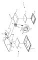
図1乃至図3は、本考案の一実施形態に係る携帯用の端末機のデュアルディスプレイモジュール構造を示す。 1 to 3 show a dual display module structure of a portable terminal according to an embodiment of the present invention.
図1に示すように、本考案の一実施形態に係るデュアルディスプレイモジュールは、メインディスプレイパネル部10と、メインディスプレイパネル部10にヒンジで結合されたサブディスプレイパネル部20とを含んでいる。
As shown in FIG. 1, a dual display module according to an embodiment of the present invention includes a main
メインディスプレイパネル部10は、相互分離可能に結合される上部及び下部ケース11、12と、この上部及び下部ケース11、12の内部に装着されるメイン平板画面13とからなる。
The main
上部ケース11のサブディスプレイパネル部20と連結される角部には、第1配線連結部14及び第1ヒンジ連結部15が連結される。
The first
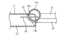
第1配線連結部14は、円筒状の連結片14a及び上部ケース11の内側へ屈曲状に凹んでいる受け片14bからなる。
The first
連結片14aは、その上部が上部ケース11の一側の角部へ突出し、その下部は上部ケース11の内側へ入り込んでいる形態で備えられ、連結片14aの突出した上部の一側面14a−1は閉鎖される。
The connecting
一方、連結片14aの上部ケース11の内側へ入り込んでいる下部は、図4に示すように、その左右の両側面14a−2、14a−3が開放されることにより、その左側面14a−2はメインディスプレイパネル部10の上部ケース11の内部と連通し、その右側面14a−3は後述するサブディスプレイパネル部20の第2配線連結部24と連通する。
On the other hand, the lower part of the connecting
このような連結片14aの上部ケース11の内へ入り込んだ下部の左右の両側面14a−2、14a−3を通じて後述するPCBフィルム30が貫通するようになる。
The
また、この連結片14aの外径は、後述するサブディスプレイパネル部20の第2配線連結部24の外径に対応する寸法からなる。
Moreover, the outer diameter of this
受け片14bは上述の連結片14aの側面から上部ケース11の内側(図5においては下方向)へ湾曲状に凹んでおり、この受け片14bの上部面に後述するサブディスプレイパネル部20の第2配線連結部24の外周面が受容されて回転支持される。
The
第1ヒンジ連結部15は、切開片15aと連結片15bとからなる。
The 1st
切開片15aには、後述するサブディスプレイパネル部20の第2ヒンジ連結部25が挿入されて回転し易い幅だけ切開して形成される。
The
連結片15bは、その一側面15b−1が開放されている円筒状であり、その外径は後述するサブディスプレイパネル部20の第2ヒンジ連結部25の外径に対応する寸法からなる。
The connecting
一方、このようなメインディスプレイパネル部10は、携帯用の端末機の本体側にホルダー型又はバー型で連結されることができる。
Meanwhile, the main
サブディスプレイパネル部20は、相互分離可能に結合される上部及び下部ケース21、22と、この上部及び下部ケース21、22の内部に装着されるサブ平板画面23とからなる。
The sub
上部ケース21のメインディスプレイパネル部10と連結される角部には、第2配線連結部24及び第2ヒンジ連結部25が形成される。
A second
第2配線連結部24は、上部ケース21の角部に備えられ、その一側面24aが開放されている円筒状からなり、上部ケース21の角部に連結されている内側面24bは上部ケース21の内側と連通するように開放され、メインディスプレイパネル部10の第1配線連結部14の受け片14bに受容されて回転支持されるように装着される。
The second
この第2配線連結部24の一側面24aの周縁部分には係合突出部24cが円周方向に突出して形成され、この係合突出部24cは第1配線連結部14の連結片14aの側に回転可能に結合され、これにより、第2配線連結部24は、係合突出部24cにより、その回転作動が案内されるとともに回転支持される。
An
一方、第2配線連結部24の開放されている一側面24aは、後述するPCBフィルム30が貫通するように、上述のメインディスプレイパネル部10の連結片14aの下部の右側面14a−3と連通する。
On the other hand, the open one
第2ヒンジ連結部25は、その一側面25aが開放されている円筒状からなり、上述のメインディスプレイパネル部20の第1ヒンジ連結部15の切開片15aの側に挿入される。
The second
一方、第2ヒンジ連結部25の一側面25aと第1ヒンジ連結部15の連結片15bの一側面15b−1とは相互連通して装着され、メインディスプレイパネル部10の第1ヒンジ連結部15とサブディスプレイパネル部20の第2ヒンジ連結部25とは相互連通して開放されている各一側面25a、15b−1を通じてヒンジ軸40が挿入されることで、メインディスプレイパネル部10及びサブディスプレイパネル部20を相対的に回転可能に結合させる。
On the other hand, one
このヒンジ軸40は、サブディスプレイパネル部20の第2ヒンジ連結部25の内径面に挿入される第1ヒンジ片41と、メインディスプレイパネル部10のヒンジ連結片15bの内径面に挿入される第2ヒンジ片42とからなる。
The
好ましくは、ヒンジ軸40は、第1ヒンジ片41の直径が第2ヒンジ片42の直径より小さく形成されることで、メインディスプレイパネル部20とサブディスプレイパネル部10との間の相対的な回転作動をより容易に行うこともできる。
Preferably, the
一方、メインディスプレイパネル部10及びサブディスプレイパネル部20は、PCBフィルム30を介して電気的に接続され、このようなPCBフィルム30はTCP(Tape Carrier Package)、COF(Chip On film)等のような軟性(Flexible)の集積回路(IC)パッケージを通称するのである。
On the other hand, the main
一方の端部がメインディスプレイパネル部10の平板画面13に接続されたPCBフィルム30は、第1配線連結部14の連結片14a及びサブディスプレイパネル部20の第2配線連結部24の夫々の開口14a−2、14a−3、24a、24bを貫通した後に、その他方の端部がサブディスプレイパネル部20の平板画面23に接続される。
The
即ち、PCBフィルム30は、メインディスプレイパネル部10及びサブディスプレイパネル部20の第1及び第2配線連結部14、24を介してメインディスプレイパネル部10及びサブディスプレイパネル部20の平板画面13、23を相互接続させるように構成される。
That is, the
以上のような本考案は、メインディスプレイパネル部10とサブディスプレイパネル部20とが第1及び第2配線連結部14、24を介して安定した電気的又は通信的な接続構造を具現することで、メインディスプレイパネル部10及びサブディスプレイパネル部20が開かれている場合に、相互間の高画質な映像コンテンツ機能を提供することができる。
In the present invention as described above, the main
また、本考案は、メインディスプレイパネル部10とサブディスプレイパネル部20とが第1及び第2ヒンジ連結部15、25により整合(clear conjunction)的に結合されることで、その開き作動の時にメインディスプレイパネル部10の平板画面13の一側にサブディスプレイパネル部20の平板画面23が正確に一致することになり、このため、二つの画面をほぼ継目のない単一の大画面に具現することができる特徴がある。
In addition, the main
以上、本考案の実施形態に係るデュアルディスプレイパネル部を有する携帯用の端末機について説明した。上述の実施形態は本考案の概念が適用された一実施形態であり、本考案の範囲が前記の実施形態に限定されるのではなく、本考案の概念をそのまま利用して様々な変形例を実施することができる。 The portable terminal having the dual display panel according to the embodiment of the present invention has been described above. The above-described embodiment is an embodiment to which the concept of the present invention is applied. The scope of the present invention is not limited to the above-described embodiment, and various modifications are made by using the concept of the present invention as it is. Can be implemented.
10…メインディスプレイパネル部、11、21…上部ケース、12、22…下部ケース、13…メイン平板画面、14…第1配線連結部、14a…連結片、14b…受け片、15…第1ヒンジ連結部、15a…切開片、15b…連結片、20…サブディスプレイパネル部、23…サブ平板画面、24…第2配線連結部、24a…一側面、24b…内側面、24c…係合突出部、25…第2ヒンジ連結部、30…PCBフィルム、40…ヒンジ軸、41…第1ヒンジ片、42…第2ヒンジ片
DESCRIPTION OF
Claims (7)
第2映像が表示される第2ディスプレイパネル部と、
前記第2ディスプレイパネル部を前記第1ディスプレイパネル部に回転可能に固定するヒンジ連結部と、
前記ヒンジ連結部と対向して設けられ、前記第1及び第2ディスプレイパネル部を電気的に連結させるための配線が挿入される配線連結部とを含む携帯用の端末機。 A first display panel unit on which a first video is displayed;
A second display panel portion on which a second video is displayed;
A hinge connecting part for rotatably fixing the second display panel part to the first display panel part;
A portable terminal including a wiring connection portion provided opposite to the hinge connection portion and into which a wire for electrically connecting the first and second display panel portions is inserted.
前記第1ディスプレイパネル部に形成され、切開片及び左右の両側面が開放されている連結片からなる第1ヒンジ連結部と、
前記第2ディスプレイパネル部に形成され、一側面が前記第1ヒンジ連結部の一側面と連通するように開放される第2ヒンジ連結部と、
前記第1及び第2ヒンジ連結部に挿入されるヒンジ軸とを含む請求項1記載の携帯用の端末機。 The hinge connecting portion is
A first hinge connecting part formed on the first display panel part and comprising an incision piece and a connecting piece whose left and right side surfaces are open;
A second hinge connection part formed on the second display panel part and open so that one side surface communicates with one side surface of the first hinge connection part;
The portable terminal according to claim 1, further comprising a hinge shaft inserted into the first and second hinge connection parts.
前記第1ディスプレイパネル部に突出するように形成される連結片、及び前記第1ディスプレイパネル部の内側へ凹んでいる受け片を含む第1配線連結部と、
前記第2ディスプレイパネル部に形成され、前記第1配線連結部の前記受け片に回転可能に装着される第2配線連結部とを含む請求項1記載の携帯用の端末機。 The wiring connecting portion is
A first wiring connection portion including a connection piece formed to protrude from the first display panel portion, and a receiving piece recessed inward of the first display panel portion;
The portable terminal according to claim 1, further comprising: a second wiring connecting portion formed on the second display panel portion and rotatably attached to the receiving piece of the first wiring connecting portion.
Applications Claiming Priority (1)
| Application Number | Priority Date | Filing Date | Title |
|---|---|---|---|
| KR20-2005-0008008U KR200387225Y1 (en) | 2005-03-24 | 2005-03-24 | Dual display module structure of portable terminal |
Publications (2)
| Publication Number | Publication Date |
|---|---|
| JP3121820U true JP3121820U (en) | 2006-06-01 |
| JP3121820U7 JP3121820U7 (en) | 2007-05-24 |
Family
ID=37034674
Family Applications (1)
| Application Number | Title | Priority Date | Filing Date |
|---|---|---|---|
| JP2006000158U Expired - Fee Related JP3121820U (en) | 2005-03-24 | 2006-01-12 | Portable terminal having dual display module structure |
Country Status (3)
| Country | Link |
|---|---|
| US (1) | US7411566B2 (en) |
| JP (1) | JP3121820U (en) |
| KR (1) | KR200387225Y1 (en) |
Families Citing this family (4)
| Publication number | Priority date | Publication date | Assignee | Title |
|---|---|---|---|---|
| WO2011136516A2 (en) * | 2010-04-28 | 2011-11-03 | Kim Si-Han | Portable display device |
| US20150085433A1 (en) | 2010-07-09 | 2015-03-26 | Si-han Kim | Portable display device |
| US9414503B2 (en) * | 2012-09-14 | 2016-08-09 | Lg Electronics Inc. | Multi-display device |
| KR101929110B1 (en) * | 2017-01-10 | 2018-12-13 | 한국기술교육대학교 산학협력단 | The case of smart phone |
Family Cites Families (4)
| Publication number | Priority date | Publication date | Assignee | Title |
|---|---|---|---|---|
| KR100377003B1 (en) | 2000-08-09 | 2003-03-26 | 김시환 | Folder type portable flat display device |
| US7271997B2 (en) * | 2003-09-18 | 2007-09-18 | Vulcan Portals, Inc. | Processor module packaging for a portable electronic device display |
| KR100456426B1 (en) * | 2004-03-12 | 2004-11-10 | 하나 마이크론(주) | Extended Display Device of Portable Terminal |
| US20080068781A1 (en) * | 2006-09-18 | 2008-03-20 | Samsung Electronics Co., Ltd. | Portable electronic device |
-
2005
- 2005-03-24 KR KR20-2005-0008008U patent/KR200387225Y1/en not_active IP Right Cessation
-
2006
- 2006-01-12 JP JP2006000158U patent/JP3121820U/en not_active Expired - Fee Related
- 2006-02-06 US US11/349,557 patent/US7411566B2/en not_active Expired - Fee Related
Also Published As
| Publication number | Publication date |
|---|---|
| US7411566B2 (en) | 2008-08-12 |
| KR200387225Y1 (en) | 2005-06-20 |
| US20060214872A1 (en) | 2006-09-28 |
Similar Documents
| Publication | Publication Date | Title |
|---|---|---|
| US7756554B2 (en) | Diversely openable dual display type mobile communication terminal | |
| US9274552B2 (en) | Multidisplay portable device | |
| US7526325B2 (en) | Triple-axis rotation folder-type portable apparatus | |
| EP1898606A2 (en) | Hinge device having a plurality of axes for a portable terminal and a connection member having the plurality of axes | |
| US7443979B2 (en) | Portable communication terminal having a housing capable of both sliding and swinging | |
| JPH1168896A (en) | Portable radio equipment | |
| JP4629577B2 (en) | Wireless terminal with two-way hinge | |
| US20060223595A1 (en) | Folder-type portable communication device having sliding display unit | |
| US7761123B2 (en) | Sliding and swing type portable terminal | |
| KR100747539B1 (en) | A cellular phone with dual LCD screens | |
| JP3121820U (en) | Portable terminal having dual display module structure | |
| US7873396B2 (en) | Portable terminal with hinge stopper | |
| US20080311958A1 (en) | Twist electronic device and methods therefor | |
| US20060172761A1 (en) | Mobile phone having dual outer liquid crystal displays | |
| KR100800827B1 (en) | Flip-up type mobile phone | |
| JP2002218030A (en) | Folding type portable terminal equipment | |
| US7200426B2 (en) | Folding cellular telephone | |
| KR100842627B1 (en) | Portable terminal | |
| JP4890743B2 (en) | Mobile phone equipment | |
| KR20040110185A (en) | Folder type mobile terminal having function multimedia message service | |
| JP2001189782A (en) | Flip type portable electronic equipment | |
| JP2003143284A (en) | Portable terminal | |
| US7974665B2 (en) | Dual-axis rotation folder-type mobile communication terminal and hinge device thereof | |
| KR20050101523A (en) | A rotating folder type mobile communication terminal | |
| KR100492001B1 (en) | A cellular phone having an rotary sub-LCD |
Legal Events
| Date | Code | Title | Description |
|---|---|---|---|
| A521 | Written amendment |
Free format text: JAPANESE INTERMEDIATE CODE: A523 Effective date: 20060313 |
|
| R150 | Certificate of patent or registration of utility model |
Free format text: JAPANESE INTERMEDIATE CODE: R150 |
|
| A623 | Registrability report |
Free format text: JAPANESE INTERMEDIATE CODE: A623 Effective date: 20061208 |
|
| R231 | Written correction (descriptions, etc.) |
Free format text: JAPANESE INTERMEDIATE CODE: R231 |
|
| A623 | Registrability report |
Free format text: JAPANESE INTERMEDIATE CODE: A623 Effective date: 20070306 |
|
| R157 | Certificate of patent or utility model (correction) |
Free format text: JAPANESE INTERMEDIATE CODE: R157 |
|
| FPAY | Renewal fee payment (event date is renewal date of database) |
Free format text: PAYMENT UNTIL: 20090510 Year of fee payment: 3 |
|
| FPAY | Renewal fee payment (event date is renewal date of database) |
Free format text: PAYMENT UNTIL: 20100510 Year of fee payment: 4 |
|
| FPAY | Renewal fee payment (event date is renewal date of database) |
Free format text: PAYMENT UNTIL: 20110510 Year of fee payment: 5 |
|
| LAPS | Cancellation because of no payment of annual fees |