JP3109601U - Powered surfboard - Google Patents
Powered surfboard Download PDFInfo
- Publication number
- JP3109601U JP3109601U JP2004007719U JP2004007719U JP3109601U JP 3109601 U JP3109601 U JP 3109601U JP 2004007719 U JP2004007719 U JP 2004007719U JP 2004007719 U JP2004007719 U JP 2004007719U JP 3109601 U JP3109601 U JP 3109601U
- Authority
- JP
- Japan
- Prior art keywords
- surfboard
- attached
- screw
- tip
- rudder
- Prior art date
- Legal status (The legal status is an assumption and is not a legal conclusion. Google has not performed a legal analysis and makes no representation as to the accuracy of the status listed.)
- Expired - Fee Related
Links
Images


Abstract
【課題】 使用者の体力の消耗を減少できる動力式サーフボードを提供する。
【解決手段】 サーフボード1は、後方に収納室11があって、収納室11には防水フレーム121を持つふた12があり、前方には穴16がある。モーター13は、収納室11内にあって、回転軸にスクリュー131があって動力として前進する。スイッチペダル141は、サーフボード1にあって、モーター13及びスクリュー131の始動と停止をコントロールする。ハンドル2は、穴16に取り付けられている。方向転換バー22は、ハンドル2の下方にあって、下方の穴221内には両側に突起部分223のあるスプリング止め具222が取り付けられている。舵23は、方向転換バー22に取り付けられている。ベルト161は、サーフボード1に取り付けられている。
【選択図】 図1PROBLEM TO BE SOLVED: To provide a power surfboard capable of reducing the wear of a user's physical strength.
A surfboard (1) has a storage chamber (11) on the rear side, the storage chamber (11) has a lid (12) having a waterproof frame (121), and a hole (16) on the front side. The motor 13 is in the storage chamber 11 and has a screw 131 on the rotating shaft and moves forward as power. The switch pedal 141 is on the surfboard 1 and controls the start and stop of the motor 13 and the screw 131. The handle 2 is attached to the hole 16. The direction change bar 22 is located below the handle 2, and a spring stopper 222 having protruding portions 223 on both sides is attached in the lower hole 221. The rudder 23 is attached to the direction change bar 22. The belt 161 is attached to the surfboard 1.
[Selection] Figure 1
Description
本考案は、動力式サーフボードに関する。本考案の動力式サーフボードは、モーター及びスクリューを動力とすることにより、海岸の岸辺からサーフィンに最も適した位置に戻ることが可能で、一往復のサーフィンにかかる時間を短縮でき、サーファーの体力の消耗も防げるという特長を持つ。また、サーフボードは、サーフィンに使用するほかに、ハンドルを組み合わせることで、水上でフローボードとして方向をコントロールしたり、方向転換したりすることが可能である。 The present invention relates to a power surfboard. The power surfboard of the present invention can return to the most suitable position for surfing from the shore by using a motor and screw as power, shortening the time required for one round of surfing, and improving the physical strength of the surfer It has the feature of preventing wear. In addition to using the surfboard for surfing, it is possible to control the direction and change the direction as a flow board on the water by combining the handle.
従来のサーフボードは、たいていサーフィンの経験があるサーファーが水上スポーツを行なう際に使用する。しかしながら、サーフィンは、熟練した技術を必要とすると同時に、優れた体力が要求される。一般に、サーフィンをする際には、サーファーは、サーフボードを使用して、波と反対の方向へ進み、海岸から遠く離れた位置まで前進し、それから、波に乗って岸まで戻って来る。 Conventional surfboards are often used by surfers with experience in surfing when doing water sports. However, surfing requires skilled skills and at the same time requires excellent physical strength. In general, when surfing, surfers use surfboards to travel in the opposite direction of the waves, move far away from the shore, and then ride the waves back to the shore.
しかしながら、繰り返される往復動作は、サーファーの体力を著しく消耗すると同時に、時間も無駄になる。体力を消耗すると、疲れるので、必然的にサーフィンの回数が減少する。また、一般に、サーフボードは、波の方向か、人の力でコントロールするかによって移動させる。普通は、サーファーが足でこれをコントロールするのであるが、ビギナーにはなかなかうまくコントロールできず、思うように楽しむことが難しい。 However, repeated reciprocating motions consumes the surfer's physical strength and wastes time. If you lose your physical strength, you will get tired and inevitably reduce the number of times you surf. In general, the surfboard is moved depending on the direction of the waves or whether it is controlled by human power. Usually, surfers control this with their feet, but beginners have a hard time controlling it, and it is difficult to enjoy as they think.
本考案の動力式サーフボードは、サーフボードにモーター及びスクリューが取り付けられていて、これを動力として前進する。したがって、サーフィンをする際、モーター及びスクリューの動力によって、サーファーが海岸から離れてサーフィンに適当な位置まで移動するのを楽にし、サーフィンの際に海岸との間を往復する時間と体力を節約することが可能である。さらに、サーフボードの前方に着脱可能なハンドル及び方向をコントロールする舵があるので、サーフィン以外にも、ハンドルと舵を使用して、方向をコントロールしたり、方向転換したりして、その他の水上スポーツを楽しむことが可能である。 The power surfboard of the present invention has a motor and a screw attached to the surfboard, and moves forward using this as power. Therefore, when surfing, the power of the motor and screw makes it easier for the surfer to move away from the shore to the right position for surfing, and saves time and physical strength to and from the shore when surfing It is possible. In addition, there is a detachable handle in front of the surfboard and a rudder that controls the direction, so in addition to surfing, you can use the handle and rudder to control the direction and change the direction, and other water sports It is possible to enjoy.
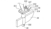
図1から図4を参照いただきたい。本考案の一実施例による動力式サーフボードは、サーフボード1にモーター13及びスクリュー131が取り付けてあり、これを動力として前進するようになっている。したがって、サーフィンをする際に、モーター13及びスクリュー131の動力によって、サーファーが海岸から離れてサーフィンに適当な位置まで移動するのを楽にし、サーフィンの際に、海岸との間を往復する時間を大幅に短縮し、同時に体力の消耗を低く抑えることが可能である。また、サーフボード1の前方に穴16があって、ここに方向をコントロールするためのハンドル2を取り付けることができる。ハンドル2の末端には折り畳み部分21があって、これはベースユニット板211とベースユニット板214が組み合わされて構成されている。そのうち、ベースユニット板214の一面にはボルト215があって、ボルト215には差し込み固定柱216及びナット217が取り付けられる。ベースユニット板211とベースユニット板214が組み合わされると、ボルト215が上に移動されて、もう一つのベースユニット板211の一面にある切り込み口212内にはまり込む。そして、ナット217が締められ、差し込み固定柱216がベースユニット板211の頂上面にある固定槽213内にはまり込んで、上方のハンドル2を固定させる(図5、図6及び図7を参照いただきたい)。折り畳み部分21の下方には別に方向転換バー22があって、サーフボード1の穴15を貫通した後、サーフボード1の下方に露出する。方向転換バー22には組み立て穴231を持つ舵23が取り付けられる。方向転換バー22の下方の穴の中には両側に突起部分223のあるスプリング止め具222が取り付けられて、突起部分223はそれぞれ方向転換バー22の両側の穴221の外に露出するようになっている。舵23が方向転換バー22に取り付けられると、スプリング止め具222の突起部分223が舵23の底面に飛び出して、舵23を固定する(図4及び図5を参照いただきたい)。さらに、取り外す際には、スプリング止め具222の両側の突起部分223を押すと、舵23を取り外すことができ、ハンドル2をサーフボード1から分離させることが可能である。したがって、サーフボード1は、普段サーフィンに使用するほかに、ハンドル2を組み合わせると、水上でフローボードとして使用でき、方向をコントロールしたり、方向を転換させたりすることが可能である。さらに、サーフボード1にスイッチペダル141を取り付けると、サーフィンの際に補助動力が必要な時、スイッチペダル141を踏むことで、モーター13及びスクリュー131を使用して、進むことができる。そして、スクリュー131の後方にねじ1321でネット132を取り付けると、安全性が増す。同時に、サーフボード1に別に電量表示メーター15を取り付けて、電池14の電量を表示することや、海底を鑑賞するための潜望鏡10を取り付けることや、サーフボード1の周囲にプロテクター100を取り付けることも可能である。プロテクター100は、複数のゴムを組み合わせるか、厚手のエアクッションからなる。前述のモーター13及びスクリュー131はサーフボード1の後方の収納室11内にあって、収納室11には防水フレーム121のあるふた12が取り付けられている(図1Aを参照いただきたい)。ふた12が閉められ、周囲の固定ねじ122によってしっかりと閉められ、ふた12は密閉度の高い防水効果を持つ。同時に、サーフボード1にはベルト161が取り付けられて、水上で使用する際にベルト161を手や体に付けておくと、水中に落ちた時にすぐにサーフボード1を引き寄せることができるので、安全である。
Please refer to FIGS. A power surfboard according to an embodiment of the present invention has a
図8及び図8Aを参照いただきたい。本考案の別の実施例によるサーフボード1の先端ボード19は、着脱可能な設計になっている。サーフボード1の先端の連結面の下縁には、差し込み穴171を持つメイン接続部分17がある。そして、連結面の上縁には1個あるいは1個以上の固定槽18があって、どの固定槽18の一側面にも下方が空洞になった固定部分182が伸びていて、一側面に挿入口181が形成されている。また、先端ボード19の連結面の下方にも挿入釘192があって、前述のメイン接続部分17にある差し込み穴171に挿入するためのサブ接続部分191がある。先端ボード19の連結面の上方にも1個あるいは1個以上の固定槽18に対応するL字型固定部分193がある。どのL字型固定部分193にも全て突起部分1941を持つスプリング194があって、組み合わせる時には、先端ボード19の連結面とサーフボード1の先端が突き合わされ、先端ボード19のどのL字型固定部分193も全てサーフボード1の先端の固定槽18の側面にある挿入口181内にはまり込むようになっている。このとき、先端ボード19は一方向にスライドし、サブ接続部分191の挿入釘192がメイン接続部分17の差し込み穴171内に挿入される。同時に、L字型固定部分193もまたスライドして固定槽18の内側にはまり込む。このとき、スプリング194の突起部分1941が固定部分182の内側のはめ込み槽1821内に進入することで、先端ボード19とサーフボード1を組み合わせて固定させる。さらに、突起部分1941の一側面にある傾斜面1942は、組み合わせる時に、固定槽18が進入しやすいようになっている。取り外す際は、スプリング194を押し、突起部分1941を固定部分182のはめ込み槽1821から離脱させ、先端ボード19を左にスライドさせると、先端ボード19が取り外せるようになっている。また、本考案のさらに別の実施例の設計は、水上で使用するフローボード3としても使用が可能である。海底や水底を鑑賞するための潜望鏡30を取り付けたり、周囲にプロテクター300を取り付けることも可能である。プロテクター300は、複数のゴムを組み合わせるか、厚手のエアクッションからなる。また、底面に連結部分31を取り付け、そこに方向をコントロールするパーツが取り付けられる。方向コントロールパーツには、ステム41の両側及び底面に方向ハンドル4及び舵42がある。人が上に乗って、両手で方向ハンドル4を握り、舵42を操作して、方向をコントロールすることができる。同時に、フローボード3の底部にはモーター32及びスクリュー321があって、動力として前進することが可能である。また、プッシュタイプの電源スイッチ34があって、モーター13の始動と停止をコントロールするようになっている。スクリュー321の後方にはねじ3221でネット322が取り付けられているので、安全である。同時に、フローボード3にはベルト35が取り付けられていて、水上で使用する際にベルト35を手や体に付けておくと、水中に落ちた時にすぐにフローボード3を引き寄せることができるので、安全である(図9を参照いただきたい)。さらに、フローボード3は、必要に応じてステム41、方向ハンドル4または舵42を取り付けないで使用することも可能である(図10を参照いただきたい)。
Please refer to FIG. 8 and FIG. 8A. The
本考案の動力式サーフボードは、サーフボードにモーター及びスクリューが取り付けられていて、これを動力として前進する。したがって、サーフィンをする際、モーター及びスクリューの動力によって、サーファーが海岸から離れてサーフィンに適当な位置まで移動するのを楽にし、サーフィンの際に海岸との間を往復する時間を大幅に短縮し、同時に体力の消耗を低く抑えるという効果がある。 The power surfboard of the present invention has a motor and a screw attached to the surfboard, and moves forward using this as power. Therefore, when surfing, the power of the motor and screw makes it easier for the surfer to move away from the shore to a suitable position for surfing, and greatly shortens the time to and from the shore when surfing. At the same time, it has the effect of keeping the exhaustion of physical strength low.
また、本考案のサーフボードは、サーフボードの前方に着脱可能なハンドル及び方向をコントロールする舵があるので、サーフィン以外にも、このハンドルと舵を使用して、方向をコントロールしたり、方向転換をしたりして、その他の水上スポーツを楽しむことが可能であるため、サーフボードとしての実用性が高いという効果がある。 In addition, since the surfboard of the present invention has a handle that can be attached and detached in front of the surfboard and a rudder that controls the direction, in addition to surfing, this handle and rudder can be used to control the direction or change the direction. In other words, since it is possible to enjoy other water sports, there is an effect that the utility as a surfboard is high.
1 サーフボード、2 ハンドル、3 フローボード、4 方向ハンドル、10 潜望鏡、11 収納室、12 ふた、13 モーター、14 電池、15 電量表示メーター、16 穴、17 メイン接続部分、18 固定槽、19 先端ボード、21 折り畳み部分、22 方向転換バー、23 舵、30 潜望鏡、31 連結部分、32 モーター、33 電池、34 電源スイッチ、35 ベルト、41 ステム、42 舵、100 プロテクター、121 防水フレーム、122 固定ねじ、131 スクリュー、132 ネット、141 スイッチペダル、161 ベルト、171 差し込み穴、181 挿入口、182 固定部分、191 サブ接続部分、192 挿入釘、193 L字型固定部分、194 スプリング、211 ベースユニット板、212 切り込み口、213 固定槽、214 ベースユニット板、215 ボルト、216 差し込み固定柱、217 ナット、221 穴、222 スプリング止め具、223 突起部分、231 組み立て穴、300 プロテクター、321 スクリュー、322 ネット、1321 ねじ、1821 はめ込み槽、1941 突起部分、1942 傾斜面、3221 ねじ 1 Surfboard, 2 handle, 3 flow board, 4 direction handle, 10 periscope, 11 storage room, 12 lid, 13 motor, 14 battery, 15 electricity meter, 16 hole, 17 main connection part, 18 fixed tank, 19 tip board , 21 Folding part, 22 Direction change bar, 23 Rudder, 30 Periscope, 31 Connecting part, 32 Motor, 33 Battery, 34 Power switch, 35 Belt, 41 Stem, 42 Rudder, 100 protector, 121 Waterproof frame, 122 Fixing screw, 131 screw, 132 net, 141 switch pedal, 161 belt, 171 insertion hole, 181 insertion port, 182 fixed part, 191 sub-connection part, 192 insertion nail, 193 L-shaped fixed part, 194 spring, 211 base unit plate, 2 2 Notch, 213 Fixing tank, 214 Base unit plate, 215 Bolt, 216 Insertion fixing column, 217 Nut, 221 hole, 222 Spring stopper, 223 Projection part, 231 Assembly hole, 300 Protector, 321 Screw, 322 Net, 1321 Screw, 1821 Fitting tank, 1941 Projection, 1942 Inclined surface, 3221 Screw
Claims (6)
前記サーフボードの収納室内にあって、収納室内には電池があり、それを電源とし、回転軸にはスクリューがあって動力として前進し、スクリューの後方にはねじでネットが取り付けられていて安全性が高くなっているモーターと、
前記サーフボードにあって、前記モーター及びスクリューの始動と停止をコントロールするためのスイッチペダルと、
前記サーフボードの前方にある穴に取り付けられ、下方には別に方向転換バーがあり、それがサーフボードの穴に挿入されてサーフボードの下方に露出し、底面と方向転換バーの間に別に折り畳み部分があって、折り畳み部分の下方はベースユニット板が組み合わされて構成されていて、ベースユニット板の一面にはボルトがあって、ボルトには差し込み固定柱及びナットが取り付けられていて、ベースユニット板が組み合わされると、ボルトが上に移動され、もう一つのベースユニット板の一面にある切り込み口内にはまり込み、ナットが締められ、差し込み固定柱がベースユニット板の頂上面にある固定槽内にはまり込んで固定されるハンドルと、
前記ハンドルの下方にあって、下方の穴内には両側に突起部分のあるスプリング止め具が取り付けられていて、突起部分はそれぞれ方向転換バーの両側の穴の外に露出するようになっていて、舵が取り付けられると、スプリング止め具の突起部分が舵の底面に飛び出して舵を固定するようになっている方向転換バーと、
前記方向転換バーに取り付けられている舵と、
サーフボードに取り付けられていて、水上で使用する際にこれを手や体に付けておくと、水中に落ちた時にすぐにサーフボードを引き寄せ可能であることにより、安全性を高めるのに役立つベルトからなり、
サーフィンをする際に、モーター及びスクリューの動力によって、サーファーが海岸から離れてサーフィンに適当な位置まで移動するのを楽にし、サーフィンの際に、海岸との間を往復する時間を大幅に短縮し、同時に体力の消耗を低く抑えることが可能であり、同時に、方向をコントロールするハンドル及び舵を取り付け可能であることにより、水上スポーツの際に方向をコントロール可能であり、方向転換も可能であることを特徴とする動力式サーフボード。 A meter for displaying the battery level and a periscope for viewing the sea floor and the bottom of the water are attached. There is a storage room in the rear, and the storage room has a lid with a waterproof frame. With a surfboard with holes,
There is a battery in the storage room of the surfboard, the battery is in the storage room, it is a power source, there is a screw on the rotating shaft and it moves forward as a power, and a net is attached to the back of the screw with a screw. With a high motor,
A switch pedal for controlling start and stop of the motor and screw in the surfboard;
It is attached to the front hole of the surfboard, and there is another direction change bar at the bottom, it is inserted into the hole of the surfboard and exposed below the surfboard, and there is another folding part between the bottom and the direction change bar. The lower part of the folding part is composed of a base unit plate, and there is a bolt on one side of the base unit plate. The bolt is moved upward, it fits into the notch on the one side of the other base unit plate, the nut is tightened, and the insertion fixing column fits into the fixing tank on the top surface of the base unit plate. A fixed handle,
Below the handle, spring stoppers with protruding portions on both sides are attached in the lower hole, and the protruding portions are respectively exposed outside the holes on both sides of the direction change bar, When the rudder is attached, the projecting part of the spring stopper jumps out to the bottom of the rudder and fixes the rudder, and
A rudder attached to the direction change bar;
It is attached to the surfboard, and if you put it on your hand or body when using it on the water, it can be pulled immediately when it falls into the water, so it consists of a belt that helps increase safety ,
When surfing, the power of the motor and screw makes it easier for the surfer to move away from the shore to the right position for surfing, and greatly shortens the time to and from the shore when surfing. At the same time, it is possible to keep the consumption of physical strength low, and at the same time, by attaching a steering wheel and rudder that controls the direction, it is possible to control the direction during water sports and to change the direction Powered surfboard characterized by
ステムの両側及び底面に方向ハンドル及び舵があって、人が上に乗って、両手で方向ハンドルを握り、舵を操作して、方向をコントロール可能である方向コントロールパーツと、
水上で使用する際にそれを手や体に付けておくと、水中に落ちた時にすぐにサーフボードを引き寄せることが可能であるために安全であるベルトからなることを特徴とするサーフボード。 It is possible to attach a periscope for appreciating the sea floor and the water floor, and a flow board with a connecting part attached to the bottom,
Direction control parts that have direction handles and rudder on both sides and bottom of the stem, people can get on, grip the direction handle with both hands, operate the rudder, and control the direction,
A surfboard that consists of a belt that is safe because it can be pulled into the water as soon as it is attached to your hand or body when used on the water.
Priority Applications (1)
| Application Number | Priority Date | Filing Date | Title |
|---|---|---|---|
| JP2004007719U JP3109601U (en) | 2004-12-28 | 2004-12-28 | Powered surfboard |
Applications Claiming Priority (1)
| Application Number | Priority Date | Filing Date | Title |
|---|---|---|---|
| JP2004007719U JP3109601U (en) | 2004-12-28 | 2004-12-28 | Powered surfboard |
Publications (1)
| Publication Number | Publication Date |
|---|---|
| JP3109601U true JP3109601U (en) | 2005-05-19 |
Family
ID=43272212
Family Applications (1)
| Application Number | Title | Priority Date | Filing Date |
|---|---|---|---|
| JP2004007719U Expired - Fee Related JP3109601U (en) | 2004-12-28 | 2004-12-28 | Powered surfboard |
Country Status (1)
| Country | Link |
|---|---|
| JP (1) | JP3109601U (en) |
Cited By (4)
| Publication number | Priority date | Publication date | Assignee | Title |
|---|---|---|---|---|
| WO2017220000A1 (en) * | 2016-06-24 | 2017-12-28 | 洛唯优 | Water paddle module apparatus |
| KR102103228B1 (en) * | 2019-05-24 | 2020-04-23 | 주식회사 스테이컴퍼니 | Powered surfing board |
| CN111284636A (en) * | 2018-12-06 | 2020-06-16 | 吉龙塑胶制品江苏有限公司 | Electric surfboard |
| WO2020242146A1 (en) * | 2019-05-24 | 2020-12-03 | 주식회사 스테이컴퍼니 | Electromotive surfboard and electromotive surfboard propulsion apparatus |
-
2004
- 2004-12-28 JP JP2004007719U patent/JP3109601U/en not_active Expired - Fee Related
Cited By (4)
| Publication number | Priority date | Publication date | Assignee | Title |
|---|---|---|---|---|
| WO2017220000A1 (en) * | 2016-06-24 | 2017-12-28 | 洛唯优 | Water paddle module apparatus |
| CN111284636A (en) * | 2018-12-06 | 2020-06-16 | 吉龙塑胶制品江苏有限公司 | Electric surfboard |
| KR102103228B1 (en) * | 2019-05-24 | 2020-04-23 | 주식회사 스테이컴퍼니 | Powered surfing board |
| WO2020242146A1 (en) * | 2019-05-24 | 2020-12-03 | 주식회사 스테이컴퍼니 | Electromotive surfboard and electromotive surfboard propulsion apparatus |
Similar Documents
| Publication | Publication Date | Title |
|---|---|---|
| US7207282B1 (en) | Propeller driven surfing device | |
| US6328617B1 (en) | Kayak paddle | |
| EP1977968B1 (en) | Propeller driven surfing device | |
| US4894033A (en) | Multipurpose and inflatable raft | |
| US6966808B1 (en) | Power surfboard | |
| US6540574B2 (en) | Foldable diving flippers | |
| US7867050B2 (en) | Paddle assist to pop-up device | |
| JP3109601U (en) | Powered surfboard | |
| US6000978A (en) | Propulsion device for snorkel board | |
| US20060292942A1 (en) | Multiple-use dynamic water surfboard device | |
| US4688509A (en) | Small-sized marine craft with deck construction providing grips | |
| MXPA06006919A (en) | Water-craft propulsion device. | |
| US5388543A (en) | Personal water surface towing device | |
| US20180195681A1 (en) | Body board with LED light rope, flexible solar panel and molded channels. | |
| JP3420937B2 (en) | Deck floor of small planing boat | |
| KR200336385Y1 (en) | Seat board for board kiting | |
| KR20090032020A (en) | Amphibian | |
| US5005506A (en) | Recreational water vehicle | |
| WO1988005745A1 (en) | Watercraft | |
| AU676174B2 (en) | Personal water surface towing device | |
| WO2005054051A8 (en) | Watercraft with propulsion by muscle power | |
| KR20060002263A (en) | Surfboard | |
| US20050172882A1 (en) | Inflatable cruising device | |
| US20090137164A1 (en) | Manually operated boat | |
| CN218703769U (en) | Rotational molding boat |
Legal Events
| Date | Code | Title | Description |
|---|---|---|---|
| R150 | Certificate of patent or registration of utility model |
Free format text: JAPANESE INTERMEDIATE CODE: R150 |
|
| LAPS | Cancellation because of no payment of annual fees |